Dr Rajiv Desai
An Educational Blog
Undersea Optical Fiber Cable
Undersea Optical Fiber Cable:
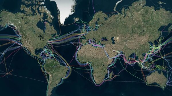
Figure above shows map of the world’s undersea communication cables.
_
Section-1
Prologue:
If you ask any average citizen, “where does the internet come from?” the answer you most likely get would be from space, via satellites. Wrong. Modern consumers have come to imagine the internet as something unseen in the atmosphere – an invisible “cloud” just above our heads, raining data down upon us. Because our devices aren’t tethered to any cables, many of us believe the whole thing is wireless but the reality is far more extraordinary. The vast majority of information that flows across the tens of billions of devices connected to the internet comes from the sea. Around 600 fiber-optic undersea cables carry more than 95% of all internet data. The fact that we route internet traffic through the ocean – amidst deep sea creatures and hydrothermal vents – runs counter to most people’s imaginings of the internet. Didn’t we develop satellites, 4G/5G and Wi-Fi to transmit signals through the air? Haven’t we moved to the cloud? The reality is that the cloud is actually under the ocean. Submarine fiber-optic cables are actually state-of-the-art global communications technologies that use light to encode information and these cables carry data faster and cheaper than satellites. These are the veins of the modern world, stretching almost 1.5 million km under the sea, connecting countries via physical cables which funnel the internet through them.
_
Every day, we send countless emails, take part in video calls, use search engines and streaming services, while seamlessly banking online. The exchange of data in the blink of an eye has become a given in much of the world – and yet we rarely pause to think about what makes it all possible: a complex global network of cables in the depths of the ocean that silently connects us. In the modern information age, undersea cables have become a strong foundation for digital connectivity. Trillions of dollars in transactions in the global economy and the continuous accessibility of information takes place through it. About 95 per cent of the international internet traffic goes through submarine cables. Even this article you are reading on your computer/mobile is carried through these cables. People know the visible access points, such as mobile networks, satellites, and fixed internet, but the underlying infrastructure that supports them is the vast network of submarine cables — our digital highways. These invisible highways, consisting of fiber-optic wires connecting landing points, are placed hundreds of metres below the surface of the ocean by cable-laying ships.
_
Telecommunications providers have used undersea cables (also known as submarine or subsea cables) for long-distance communications for more than 170 years. The English Channel Submarine Telegraph Company laid the first undersea cable in 1850 between England and France, to enable international communications over telegraph. The first successful transatlantic telegraph message carried by undersea cable was transmitted in 1858, the first transatlantic telephone cable entered operation in 1956, and the first transatlantic fiber-optic cable was laid in 1988 and called the TAT-8, that had the capacity to carry 40,000 telephone connections simultaneously, four times the capacity of previous cables. Today, more than 600 cables span 1.5 million kilometers globally enough to circle the Earth more than 35 times and connect to more than 1,700 landing stations (i.e., the point where the undersea cable makes landfall). The ocean’s fibre optic network links major data hubs like New York, London, Tokyo, and Sydney, while also increasingly reaching into developing regions to help bridge the global digital divide. The cables connect every continent except Antarctica, and serve as the backbone for the global internet. Industry experts estimate that the undersea telecommunication cable network carries about 95% of intercontinental global internet traffic, and 99% of transoceanic digital communications (e.g., voice, video and data) including trillions in international financial transactions daily.
_
Subsea fiber-optic cables are the world’s primary conduit for data, carrying 95 percent of data internationally, making them essential to the modern digital world and indispensable to both national and economic security. Subsea cable infrastructure impacts nearly all aspects of daily life by providing access to the internet and delivering the data that underlies critical systems such as e-commerce and financial networks, communications, and telehealth and e-education. It is also a key part of the foundation for seismic, cutting-edge technologies such as AI, cloud computing, and quantum computing. All told, these cables are essential for the daily communications of billions of people and businesses. In 2023, undersea cables carried an estimated US$10 trillion worth of financial transactions every day. As a consequence, subsea cables are considered critical infrastructure by many governments. Most of the cables carrying our voice, data, and streaming images lie remarkably exposed on seafloors, on average, about 3,600 meters deep. 2Africa is the longest subsea cable in the world, at 45,000 kilometers long, connecting 46 cable landing stations across 33 countries.
_
Every ChatGPT prompt, every AI-generated insight, every high-frequency stock market trade, and every classified military order sent across the world depends on infrastructure few ever think about: undersea data cables. These cables carry 95% of the world’s data traffic, yet they remain almost entirely unprotected, unregulated, and unmonitored. The undersea cables that carry Internet traffic around the world are an understudied and often underappreciated element of modern Internet geopolitics, security, and resilience. Without these cables, the Internet would not exist as it does today. These cables are largely owned by private companies, often in partnership with one another, though some firms involved in cable management are state-controlled or intergovernmental. Submarine cables are, therefore, a major vector of influence that companies have on the global Internet’s shape, behavior, and security. Not only does the private sector manage large swaths of the constituent networks that compose the broader Internet, it also builds, owns, manages, and repairs the underlying physical infrastructure. More than 200 private operators control a network of 900,000 miles of undersea fiber-optic cable.
_
Comprising more than 1.5 million kilometers of subsea fibre‑optics network is the indispensable infrastructure of the 21st century. But as our dependency has increased, security remains a challenge. Funnelled through exposed choke points (often with minimal protection) and their isolated deep-sea locations entirely public, the arteries upon which the Internet and our modern world depend have been left highly vulnerable. Whether from terrorist activity or an increasingly bellicose Russian/Chinese naval presence, the threat of these vulnerabilities being exploited is growing. A successful attack would deal a crippling blow to Ukraine’s/Taiwan’s security and prosperity. The threat is nothing short of existential. If some of these cables were cut, global communications would be severely slowed. If all of them were cut, the global internet would cease to exist. For instance, if the 40 cables connecting the US to the rest of the world were severed, it is estimated that only 7% of US internet traffic could be carried by alternate satellite infrastructure (Liu et al., 2020).
_
Even with the growth of satellite internet and land-based fiber, submarine cables are still the main way the world stays connected online. About 95% of intercontinental data traffic travels through these cables, showing their unmatched capacity and reliability. As demand for internet bandwidth rises, these cables carry most of the data needed for cloud computing, AI, streaming, and finance. A growing demand for greater bandwidth, shorter latency, and improved remote communications is leading to even greater dependence on subsea cables. Yet, despite their importance, subsea cables and their associated shore-based landing stations can be damaged by natural processes and human activities. The International Cable Protection Committee reports 150 to 200 cases of cable damage each year, mostly from fishing and ship anchors. This makes resilience and protection more important than ever. Repair costs can reach millions of dollars, with further, more financially significant knock-on effects as underlined in a UK Policy Exchange Report: “The effect (of cable breaks) on international finance, military logistics, medicine, commerce and agriculture in a global economy would be profound… When communications networks go down, the financial services sector does not grind to a halt. It snaps to a halt.”. To remain resilient, it is crucially important that the cable network is future-proofed to anticipate and withstand environmental and anthropogenic hazards as much as practicable.
_
Undersea fiber optic cables are the unsung heroes of our interconnected world, serving as the invisible arteries that facilitate global communication and data exchange. To view a map of the world’s undersea cable networks is to understand which countries and commercial hubs command the greatest flows of wealth, knowledge, and power. As such, the most densely packed clusters of cables originate and terminate between the United States (US) and Europe, and these same places have major arterials connecting to economic hubs in Asia, namely Japan, China, Taiwan, and about a dozen other places. Sub-sea thoroughfares – transatlantic, transpacific, Africa–Europe, and intra-Asia subsea links carry data of hundreds of terabits per second, dwarfing terrestrial routes. Land-based linkages – all terrestrial cross-border routes combined account for less than one percent of global internet traffic, making them a rounding error in comparison. Modern undersea fiber-optic cables carry massive amounts of data, with top-tier systems boasting capacities exceeding 200 terabits per second (Tbps). Undersea fiber optic cables have a lifespan of 25 years. Without these cables, global communication, commerce, and government systems would come to a screeching halt. But despite their critical role, few people are aware of their existence — or their fragility. I have published articles on computer & internet, 5G, artificial intelligence and quantum computing. Today it’s time for undersea (submarine) communication (fiber-optics) cables, the backbone of modern world.
_____
_____
Acronyms and abbreviations:
AT&T = American Telephone and Telegraph Company
CBD = Convention on Biological Diversity
CPZ = Cable protection zone
DTS = Desktop study
EEZ = Exclusive economic zone
FAD = Fish aggregating devices
FAO = Food and Agriculture Organization of the United Nations
GCCS = Geneva Convention on the Continental Shelf
GCHS = Geneva Convention on the High Seas
GISS = Goddard Institute for Space Studies, NASA
GPS = Global positioning system
ICES = International Council for the Exploration of the Sea
ICPC = International Cable Protection Committee
IEEE = Institute of Electrical and Electronic Engineers, USA
IPCC = Intergovernmental Panel on Climate Change
ITLOS = International Tribunal for the Law of the Sea
NASA = National Aeronautics and Space Administration, USA
NOAA = National Oceanic and Atmospheric Administration, USA
ROV = Remotely operated vehicle
SCIG = Submarine Cable Improvement Group
TAT-1 = Trans-Atlantic Telephone, first trans-ocean telephone cable
UNCLOS = United Nations Convention on the Law of the Sea
UNEP = United Nations Environment Programme
UNESCO = United Nations Educational, Scientific and Cultural Organization
ASIC = Application Specific Integrated Circuit
Mux = Multiplexer
DSP = Digital Signal Processor
DAC = Digital to Analog Converter
ADC = Analog to Digital Converter
BU = Branching Unit
DART = Deep-ocean Assessment and Reporting of Tsunami buoy system
ICT = Information and Communication Technologies
ITU = International Telecommunication Union
DC = Data Centre
DWDM = Dense WDM
EDFA = Erbium-Doped Fibre Amplifier
LD = Laser Diode
MC-EDF = Multicore Erbium-Doped Fibre
MCF = Multicore Fibre
MMF = Multimode fiber
MDL = Mode-Dependent Loss
MDM = Mode Division Multiplexing
MIMO = Multiple-Input Multiple-Output
O/E = Optical signal to Electrical signal converter
OSNR = Optical Signal-to-Noise Ratio
SCF = Single-Core Fiber
SDM = Space Division Multiplexing
SMF = Single-Mode Fibre
SNR = Signal-to-Noise Ratio
TDM = Time Division Multiplexing
WDM = Wavelength Division Multiplexing
Fiber = Fibre
RFS = ready for service
DAS = Distributed Acoustic Sensing
OTDR = Optical Time Domain Reflectometry
SS-TDR = Spread-spectrum time-domain reflectometry
PFE = Power feed equipment
ROADM = Reconfigurable optical add-drop multiplexer
CLS = cable landing station
SLTE = submarine line terminal equipment
RF = radio frequency
PCS = probabilistic constellation shaping
ROPA = remote optical pump amplifier
PSCF = Pure-Silica-Core Fiber
______
______
Glossary:
Armour – normally galvanized steel wires (of circular cross-section) laid around the core of the cable to provide both tensile strength and protection from external damage.
Bight – a U-shaped loop of cable or rope. Often refers to the single U-shaped loop of cable payed out from a cable ship as a final splice, or to the U-shaped loop of cable exiting the cable tank in which a repeater is positioned.
Bottom otter trawl – a cone-shaped net attached by trawl lines to a fishing vessel and dragged across the ocean floor.
Branching unit (BU) – a sub-sea unit used at the point where a fibre-optic cable system splits into two legs, i.e. the fibres are split and may go to two terminals or to other branching units. Some branching units have the capability of switching the fibres from one leg to another.
Burial assessment survey (BAS) – a survey of the seabed to determine the likely success of any type of burial operation and to assist in the appropriate selection of cable armouring. Different combinations of tools may be used to constitute a BAS. For instance, it may be invasive and continuous, such as a mini-plough or grapnel-shaped tool. Alternatively, sampling can be carried out at discrete sites using techniques such as cone penetrometer tests (CPTs), or by sediment coring. Geophysical methods, such as resistivity or seismic reflection, can be used, or any combination of the above.
Cable network – a regional to global grouping of interconnected submarine cables, including repeaters and landing stations. A network provides redundancy in the event of a cable failure, in which instance voice and data traffic can be re-routed via intact parts of the network.
Cable protection zone – a defined area, usually identified on official marine charts, where submarine cables are afforded legal protection supported by various policing measures. Cable protection zones extending beyond territorial seas, normally 12 nautical miles, are generally not recognized under international law.
Cable route survey – a marine survey operation to obtain all the necessary information to design and engineer a cost-effective and reliable submarine cable system. Following receipt of the survey report, the installation cable route is optimized on the basis of data obtained on the seabed bathymetry (depth contours etc.), character, sediment thickness, marine life and other useful information such as currents, temperatures and prevailing weather conditions. The survey determines whether cable burial is required or indeed possible. A cable route survey is a prerequisite to laying a submarine cable and is integral to the freedom to lay and maintain international submarine cables under UNCLOS.
Cable vessel (also cable ship) – a vessel purpose-built or modified to lay and repair submarine cables. When engaged in such operations, the cable vessel displays special insignia or ‘shapes’ and navigation lights to alert other vessels to its restricted manoeuvrability as required by international law.
Component failure – whereby a constituent part of a cable fails and produces a fault. Failures of this type account for 7 per cent of all cable faults.
Continental shelf – a zone, adjacent to a continent or island, which extends from the coast as a gently sloping plain (0.1º) to the shelf edge, where the seabed steepens to form the continental slope. The average depth of the shelf edge is 135 m. The precise limits of a nation’s legal continental shelf boundary claim beyond the EEZ are determined in accordance with criteria set forth in UNCLOS, but in no case shall extend beyond 350 nautical miles from the coastal state’s coastal baseline.
Continental slope – a zone of relatively steep seabed (36º), extending from the shelf edge to the deep ocean. The slope is often incised by submarine canyons and/ or landslides.
Deep-ocean trench – a long, narrow, steep-sided depression of the ocean floor that includes the deepest parts of the ocean.
Desktop study – a review of published and unpublished information which, in the context of submarine cables, provides an initial assessment of engineering, environmental and legal factors relating to a cable route.
Exclusive economic zone (EEZ) – an area beyond and adjacent to the territorial sea that is subject to the specific legal regime established under UNCLOS. The EEZ extends to a maximum of 200 nautical miles from a coastal state’s coastal baseline.
External human aggression fault – a cable fault caused by an external force, in this case by human activities such as fishing, anchoring, dredging, drilling etc.
External natural aggression fault – a cable fault caused by external natural forces such as submarine landslides and turbidity currents triggered by earthquakes.
Fish aggregating device (FAD) – various types of artificial float, either drifting or anchored to the seabed, designed to attract pelagic (mid-water-dwelling) fish including tuna and marlin.
Global positioning system (GPS) – a global navigation system designed to provide accurate positional and navigational information derived from a constellation of 24 to 32 satellites.
Grapnel – a specialized hooked device used to recover sub marine cables for repair or removal. Smaller grapnels are used by some fishermen to recover lost fishing gear.
Gutta percha – a natural gum from trees found on the Malay Peninsula and elsewhere; used to insulate submarine cables until the 1930s, when it was replaced by more durable plastics.
High seas – open ocean that is not within the territorial waters or jurisdiction of any particular state. The high seas are open to all states, whether coastal or landlocked. Freedoms of the high seas are exercised under the conditions laid down by UNCLOS and other rules of international law.
Hydrothermal vents – include fissures and fractures from which hot, often mineral-rich waters are expelled, especially along mid-ocean ridges and hotspots. Waters can reach +350ºC, but rapidly cool in the cold ocean, forcing the precipitation of minerals.
International Tribunal for the Law of the Sea (ITLOS) – an independent judicial body, located in Hamburg, Federal Republic of Germany, established under UNCLOS, to adjudicate disputes arising out of the interpretation and application of the Convention.
Marine protected area – a formally designated area of open or coastal ocean whose natural and cultural resources are protected and managed by legal or other effective means.
Mid-ocean ridges – continuous mountain ranges that have formed along the central reaches of the main oceans. They mark the zones where tectonic plates drift apart to allow magma to upwell and form new volcanic crust/ seafloor.
Multibeam systems – a ship-based or towed acoustic mapping system that allows swaths of seabed, up to tens of kilometres wide depending on water depth, to be accurately mapped during a single survey run.
Natural hazard – a naturally occurring physical phenomenon caused by rapid- or slow-onset events under the influence of atmospheric, oceanic or geological forces operating on time scales of hours to millennia.
Notice to mariners – published notifications that advise of changes in navigational aids, new hazards such as shipwrecks, new offshore installations, changes in water depth, submarine cable locations and operations, and other matters. This procedure allows for the constant updating of navigational charts.
Optical amplifier – uses special fibres and a laser pump to amplify an optical signal. This is done without the optical signal being regenerated by conversion to an electrical signal and converted back into an optical signal (as is the case with optical regenerators). Submarine optical amplifiers are packaged in housings in a manner similar to repeaters and continue to be referred to as repeaters.
Optical fault – a fault caused by damage to the glass optical fibres in a submarine cable.
Otterboards – (also called trawl doors) typically heavy rectangular, oval or curved plates of metal or wood connected by the trawl lines to a fishing vessel and designed to keep the mouth of the net open.
Plough burial – burial of the cable into the seabed for enhanced cable protection. The cable is guided into a self-closing furrow cut by a sea plough towed by a cable ship.
Post-lay inspection (PLI) – an inspection conducted after deployment of a cable on or into the seabed to ens ure correct placement and to monitor any subsequent environmental effects.
Post-lay inspection and burial (PLIB) – an operation usually carried out by an ROV in areas of plough burial after the cable installation. The inspection operation confirms the burial depth. If necessary, additional burial (usually by jetting) can be implemented in localized areas, e.g. at ‘plough skips’ where the plough has been recovered for repair or maintenance.
Remotely operated vehicle (ROV) – an un manned submersible vehicle used to inspect, bury or exhume cables. They can also be used, inter alia, to carry out surveys and inspection of the cable on the seabed. ROVs are usually fitted with cameras and cable tracking equipment, and for burial operations can be fitted with jetting or trenching tools. ROVs are controlled from surface vessels and operate mainly in waters shallower than 2,000 m.
Repeater – a submerged housing containing equipment that boosts the telecommunications signal at regular intervals along the cable. Each repeater is powered via an electrical current that is fed into the submarine cable system from the shore-based terminal stations. All telecommunications signals lose strength in proportion to the distance travelled, which explains why repeaters are only required on the longer submarine cable routes. The term ‘repeater’ originated in the telegraph era and has continued in use as a generic term to describe the submerged signal boosting equipment that has been required in all of the longer submarine cable systems, regardless of the transmission technology used. In a modern fibre-optic submarine cable system, the repeater spacing is typically 70 km.
Sand waves – a condition where the seabed is covered by sand waves whose movement may expose previously buried cable.
Seamount – submarine elevation with the form of a mountain whose size differentiates it from small elevations such as pinnacles, banks and knolls.
Shunt fault – occurs when a cable’s insulation is damaged or degraded. This exposes the copper conductor carrying electrical current, which passes or ‘shorts’ into the ocean.
Side-scan sonar – an acoustic technique to map the reflectivity of seabed material to identify potential obstructions on the seabed. Used primarily during surveys prior to ploughing operations. The use of side-scan sonar is helpful in cable repair operations in identifying surface-laid cables and in localizing fault locations.
Strumming – a term used to describe the standing wave vibration set up in unsupported cable during deployment or when in suspension between localized high sectors on the seabed. Strumming is induced by the drag forces generated when water currents flow across the cable in suspension.
Sub-bottom profiler (SBP) – an acoustic method of determining the vertical geological structure of the upper seabed. SBP equipment releases low-power, high-frequency, short pulses of acoustic energy into the water column and measures energy reflected back from the seabed and from layers below the seabed, revealing the differing physical properties of those layers. For cables, this information helps define potential hazards and the availability of sediment suitable for cable burial.
Submarine canyon – a narrow, steep-sided, V-shaped depression, typically incised into the continental shelf and slope.
Submarine channel – a shallow to steep-sided depression that may be fed by one or more submarine canyons. Compared to canyons, channels usually have V- to U shaped profiles, are often bordered by well-developed levee systems, are longer and extend to greater ocean depths.
Submarine coaxial cable – a telephonic communications system comprising inner and outer copper conductors separated by a polyethylene insulator. This design re placed telegraphic cables in the 1950s, and was later replaced by fibre-optic designs.
Submarine fibre-optic cable – a communications system in which digitized data and voice signals are converted to coded light pulses and transmitted along optical glass fibres. Fibre-optic cables replaced coaxial cables in the 1980s.
Submarine landslides – a general term that encompasses mainly gravity-driven, downward and outward movements of sediment and rock. They frequently occur on, but are not confined to, continental slopes, especially those in seismically active regions.
Submarine telegraphic cable – an earlier communications system in which coded electrical impulses were trans mitted through an insulated copper wire conductor.
Suspension – a term used to describe an unsupported length of cable held in a catenary by the residual cable tension at each side of the suspension. Suspended cables can suffer damage at the contact points where abrasion (chafe) can occur and may be subject to strumming.
Tectonic plate – a large, relatively rigid segment of the Earth’s crust and upper mantle that moves horizontally and interacts with other plates to produce seismic, volcanic and tectonic activity.
Territorial sea – refers to a state’s coastal waters, which extend out to 12 nautical miles from a baseline commonly defined by the mean low water mark. Territorial sea limits and permitted activities in territorial seas are determined in accordance with UNCLOS and international law.
Tsunami – waves of great wavelength, usually generated by earthquakes or submarine landslides; not to be confused with ‘tidal waves’, which result from astronomical forces on the ocean.
Turbidity current – a dense, sediment-laden current that flows rapidly across the ocean floor, often via submarine canyons and channels. Turbidity currents can be triggered by earthquakes, storms and river floods, and are capable of breaking submarine cables.
United Nations Convention on the Law of the Sea (UNCLOS), 1982 – a convention known as the ‘constitution of the world’s oceans’ that entered into force in 1994. UNCLOS establishes a legal framework to govern all ocean space, its uses and resources. It contains provisions relating to the territorial sea, the contiguous zone, the legal continental shelf, the exclusive economic zone and the high seas. UNCLOS defines freedoms and responsibilities for international submarine cables, navigation and other activities within these zones. It also provides for environmental protection and preservation, marine scientific research, and the development and transfer of marine technology.
______
______
Section-2
History of submarine cables:
A submarine cable is a fiber optic cable laid in the ocean, connecting two or more landing points. Rarely much wider than a garden hose, today cables generally comprise of the optical fibers that carry the information, which are then covered in silicone gel, then sheathed in varying layers of plastic, steel wiring, copper, and nylon in order to provide insulation to protect the signal and protect the cable from damage from wildlife, anchors & fishing, or weather & other natural events. The cables are laid using ships that are modified specifically for this purpose, transporting and slowly laying the ‘wet plant’ infrastructure on the seabed. These special ships can carry thousands of kilometers of optical cable out to sea. A special subsea plow is also used to trough and bury submarine cables along the seabed closer to shorelines where naval activities, such as anchoring and fishing, are most prevalent and could damage submarine cables.
_
Subsea cables; connecting the world for 170 years:
We’ve had submarine cables for over 170 years and they’ve really been a way for communication between countries and continents. Work to demonstrate the potential of subsea cables began in the 1840s, when Samuel Morse, the inventor of Morse Code, submerged a wire insulated with tarred hemp and India rubber, in the water of New York Harbor and telegraphed through it in 1842. Here is the chronology of Telegraph, Telephone and Fiber-optic era, the three services reaching across the Atlantic.
_____
Telegraph cables:
Telegraphy involved the transmission of coded electrical impulses through a conductor, which in a submarine cable was a stranded copper wire with gutta percha insulation wrapped in brass or jute tape. Inventions involving telegraphy escalated through the19th century. In 1836, English chemist and inventor, Edward Davey, came close to completing a practical telegraph system. He envisioned an electric telegraph that could be insulated for protection and placed underwater with relay-type ‘repeaters’ to boost weak signals along the cable. This was the forerunner of the submarine telegraph cable. Close to success, Davey unexpectedly departed for Australia, leaving his main competitors, William Cooke and Charles Wheatstone, to complete an operational telegraph (Stumpers, 1884; Ash et al., 2000). Their system was patented in 1837 and involved the identification of alphabetic letters by deflections of magnetic needles. At about the same time, Samuel Morse patented a telegraph based on an electromagnetic system that marked lines on a paper strip. The technique came into commercial reality in 1844 when a communications link was made between Baltimore and Washington, DC.
_
The concept of insulating submarine telegraph cables to make them durable, waterproof and sufficiently strong to withstand waves and currents, fostered several trials with different materials. In 1843, Samuel Morse produced a prototype by coating a hemp-covered cable in tar and pitch; insulation provided by a layer of rubber also gave the cable strength and durability (Ash et al., 2000). By the late 1840s, the basic technology existed to manufacture submarine cables, and in 1848 the Gutta Percha Company received its first order for wire insulated with a newly discovered natural polymer from Malaya – gutta percha (Kimberlin, 1994; Gordon, 2002; ICPC, 2007).
_
An English merchant family, headed by the brothers James and John Brett, financed a submarine cable across the English Channel from Dover to Calais. Constructed from copper wire and gutta percha without any form of protection, the cable was laid by the tug Goliath on 28 August 1850 (Kimberlin, 1994; Ash et al., 2000; Gordon, 2002). The cable lasted for just a few messages before it succumbed to vigorous waves and currents. A year later it was replaced by a more robust design comprising four copper conductors, each double coated with gutta percha, bound with hemp and heavily armoured with iron wires. This improved version extended the cables’ working life to a decade. After installation, John Brett sent a special message to soon-to-be Emperor of France, Napoleon III – an act that symbolically marked the day that submarine telecommunications became an industry. By 1852, cables also connected England to the Netherlands and Germany, with other links between Denmark and Sweden, Italy and Corsica, and Sardinia and Africa. Submarine cables of that time were far from perfect. The copper used for the conductors tended to be hard, brittle and poorly conductive, while the gutta percha insulation was sometimes lumpy and only moderately flexible. There was a need to improve cable design and materials as the emerging communications industry looked to the Atlantic Ocean as the next great challenge. Such a communications link would allow British and American businesses to develop trade – particularly the British cotton industry.
_
In 1854, Cyrus Field, a wealthy American paper merchant, became interested in laying a telegraph cable across the Atlantic Ocean (Gordon, 2002). Along with John Brett and Sir Charles Bright, he founded the Atlantic Telegraph Company in 1856 (Ash et al., 2000). Its board members included William Thomson, the eminent physicist who later became Lord Kelvin. After an unsuccessful attempt in 1857, the company laid the first trans-Atlantic cable in 1858, when Ireland was linked to Newfoundland. However, success was short lived, and after 26 days of operation the cable failed. Following three other attempts, a new and improved cable was laid in 1866 from the Great Easterncable ship by the Telegraph Construction & Maintenance Company (TELCON) – a merger of the Gutta Percha Company and Glass, Elliot & Company. The new and more durable cable provided reasonably reliable communication at around 12 words per minute across the Atlantic. On its return journey to England, the Great Eastern recovered the cable lost the year before. A repair was made and connection with Newfoundland completed to provide a second trans-Atlantic cable link (Ash et al., 2000; Gordon, 2002).
_
As telegraph technology and laying techniques improved, the submarine network expanded greatly. To facilitate government and trade, cables linked the United Kingdom with the many outposts of its empire. By the early 20th century, much of the world was connected by a network that enabled rapid communication and dissemination of information for government, commerce and the public.
The durability and performance of telegraph cables improved with new conducting, strengthening and insulating materials. Alloy tapes and wires, such as the iron nickel, permalloy, and the copper-iron-nickel, mu-metal, were used to increase cable performance (particularly the speed of signalling) in the 1920s. Staff employed to send and receive telegraphic messages at relay stations were gradually replaced by electro-mechanical signallers. Transmission speeds increased progressively, and by the late 1920s speeds exceeding 200 words per minute became the norm.
_
By the 1930s there were just two cable manufacturers in Britain, TELCON and Siemens Brothers. The Great Depression and competition from radio-based communications made business difficult. As a result, TELCON merged with the submarine communications cable section of Siemens Brothers to form Submarine Cables Limited. Despite the technological advances of the telegraph, the developing radio industry could do something that the telegraph could not – namely produce intercontinental voice communications. Marconi’s company, Imperial, owned the patent to radio communication; it joined forces with the cable industry after they were encouraged to merge by the UK government. And so, in 1934, Cable & Wireless was born. The new partnership enabled even more rapid communications, which came into their own during the Second World War. Radio was used for communicating with troops, and submarine cables provided secure networks that could not be intercepted easily.
______
Telephone cables:
Following Alexander Graham Bell’s invention of the telephone in 1875, it was only a matter of time before phone lines linked continents by submarine cables. Initial attempts in the United States and United Kingdom met with limited success. The British Post Office laid a telephone cable across the English Channel, but inherent deficiencies of the gutta percha insulation meant that signals were limited to short distances before they became distorted. Coaxial or analogue cables came into use in the 1950s and continued for the next 40 years and more. They differed from telegraph cables in three key ways:
-1. Instead of gutta percha, polyethylene was used exclusively as the insulator or dielectric. It also formed the outer sheath of deep-ocean designs
-2. The cable core had a coaxial structure consisting of an inner and outer conductor of copper separated by polyethylene insulation material.
-3. The first trans-Atlantic analogue cable (TAT-1) used traditional armour for strength. However, later cables used fine-stranded, high tensile strength steel wires encased in the central conductor.
The discovery of polyethylene in 1933 made trans-oceanic telephony possible. In 1938, a polyethylene-encased cable was developed with a copper coaxial core capable of carrying a number of voice channels. That innovation, along with the use of repeaters to boost the signals, meant that a trans-oceanic cable with multiple voice channels was achievable. Thus in 1955–1956, two cables were laid between Scotland and Newfoundland as a joint venture between the British Post Office, American Telephone and Telegraph (AT&T) and the Canadian Overseas Telecommunications Corporation. The system, named TAT-1, came into service on 25 September 1956, and in the first day of operation carried 707 calls between London and North America. The era of submarine coaxial telephone communications had begun. With it came a suite of technological developments relating to the design of signal-boosting repeaters, new methods of cable laying and improved methods of strengthening cables, especially in deep water where as much as 6 km of cable could be suspended through the water as it was laid on the ocean floor from a cable ship.
_
In the 1970s and early 1980s, these relatively low bandwidth cables were only cost-effective on high-density communication routes, with the bulk of global trans-oceanic traffic carried by satellites. The last coaxial system across the Atlantic Ocean was TAT-7, which had a capacity of 4,000 telephone channels. However, to achieve this repeater had to be installed at 9 km intervals, which made the technology very expensive. A more cost-effective solution was needed to meet the increasing demand for more capacity at reasonable cost. The race to develop fibre-optic technology for application in submarine cables began in the mid-1970s, thus heralding the dawn of another technological revolution in submarine communications.
_____
Fiber-optic cables:
During the late 1970s and early 1980s, development focused on fibre-optic submarine cables that relied on a special property of pure glass fibres, namely to transmit light by internal reflection. By coding information as light pulses, data could be sent rapidly around the world. Glass fibres could carry 12,000 telephone channels, compared to 5,500 for the most advanced coaxial cable. Furthermore, the quality of fibre-optic communication was superior. However, at this stage it was difficult to envisage that fibreoptic cables would form a global network. Over the next decade, scientists continued to improve and refine fibreoptic technology. The world’s first trial of a submarine fibre-optic cable was in Loch Fyne in 1979 (Ash et al., 2000). The trials proved that the cable could withstand the mechanical stresses involved in laying, as well as retaining the required stability of transmission characteristics. By 1986, the first international system was installed across the English Channel to link the United Kingdom and Belgium. In 1988, the first trans-oceanic fibre-optic cable was installed, which marked the transition when sub marine cables started to outperform satellites in terms of the volume, speed and economics of data and voice communications. TAT-8 linked the United States, United Kingdom and France and allowed for a large increase in capacity. At about that time, the internet began to take shape. As newer and higher-capacity cable systems evolved, they had large bandwidth at sufficiently low cost to provide the necessary economic base to allow the internet to grow. In essence, the two technologies complemented each other perfectly: cables carried large volumes of voice and data traffic with speed and security; the internet made that data and information accessible and usable for a multitude of purposes. As a result, communications, business, commerce, education and entertainment underwent radical change.
_
Despite the success of submarine telecommunications, satellite transmission remains a necessary adjunct. Satellites provide global broadcasts and communications for sparsely populated regions not served by cables. They also form a strategic back-up for disaster-prone regions. By comparison, submarine cables securely and consistently deliver very high-capacity communications between population centres. Such links are also cost-effective, and the advantages of low cost and high bandwidth are becoming attractive to governments with low population densities. The amount of modern submarine fibre-optic cables laid in the world’s oceans has exceeded a million kilometres and under pins the international internet. Almost all transoceanic telecommunications are now routed via the submarine cable network instead of satellite.
______
Evolution of cable technology steps: telegraph, coaxial-voice and fiber-optics:
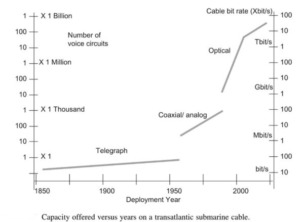
Between 1850 and 2015, the submarine cable network has been able to provide a full range of services from telegraph messages, telephone, fax, data and now video and multimedia by Internet, as well as unlimited cloud and big data applications. One million kilometers of cables are spread through the oceans, each having a multiterabit communication capacity. The capacity offered to telecommunications users from the year 1850 to 2015 is shown in Figure below, which displays clearly the three technology steps: telegraph technology, then coaxial voice communication, and finally the fiber optic era as applied over a transatlantic cable. There are 10 orders of magnitudes in terms of capacity between the first telegraph cable and the more modern optical system.
_
Figure below shows capacity offered versus years on a transatlantic submarine cable.
_____
Undersea fiber optic systems today are made up of four parts:
First, there is the fiber itself. An undersea fiber-optic cable is made up of multiple pairs of fibers. The optic fiber used in undersea cables is of the highest clarity permitting runs of more than 100 kilometers between repeaters. The fibers themselves are coated in seven layers of metals and composites to protect the cable.
The next part of the system are repeaters. Since optical signals are limited to between 100-400km because of signal loss, repeaters are used to regenerate the light wave during the long ocean trip. Repeaters are powered by a constant direct current passed down a conductor near the center of the cable. All repeaters in a cable are powered in series. Power feed equipment (PFE) is installed at the terminal stations on the land. These PFEs inject huge voltage into the line – 3,000, 4,000, and up to 10,000 volts – to power each repeater on the cable.
The last two parts of an undersea fiber optic system are the cable landing point and cable termination station. The landing point is the where the cable makes landfall. The termination station is where the cable connects to the terrestrial network. These four major components form an undersea cable system. Originally, submarine cables were simple point-to-point connections. With the development of submarine branching units (SBUs), more than one destination could be served by a single cable system.
_
The type of optical fiber used in unrepeated and very long cables is often PSCF (Pure-Silica-Core Fiber) due to its low loss of 0.172 dB per kilometer when carrying a 1550 nm wavelength laser light. The large chromatic dispersion of PSCF means that its use requires transmission and receiving equipment designed with this in mind; this property can also be used to reduce interference when transmitting multiple channels through a single fiber using wavelength division multiplexing (WDM), which allows for multiple optical carrier channels to be transmitted through a single fiber, each carrying its own information. WDM is limited by the optical bandwidth of the amplifiers used to transmit data through the cable and by the spacing between the frequencies of the optical carriers; however, this minimum spacing is also limited, with the minimum spacing often being 50 GHz (0.4 nm).
_
WDM or wavelength division multiplexing was first implemented in submarine fiber optic cables from the 1990s to the 2000s, followed by DWDM or dense wavelength division multiplexing around 2007. Each fiber can carry 40 to 80 wavelengths at a time. SDM or spatial division multiplexing submarine cables have at least 12 fiber pairs which is an increase from the maximum of 8 pairs found in conventional submarine cables, and submarine cables with up to 24 fiber pairs have been deployed. The type of modulation employed in a submarine cable can have a major impact in its capacity. SDM is combined with DWDM to improve capacity.
_
Transponders are used to send data through the cable. The open cable concept allows for the design of a submarine cable independently of the transponders that will be used to transmit data through the cable. SLTE (Submarine Line Terminal Equipment) has transponders and a ROADM (Reconfigurable optical add-drop multiplexer) used for handling the signals in the cable via software control. The ROADM is used to improve the reliability of the cable by allowing it to operate even if it has faults. This equipment is located inside a cable landing station (CLS). C-OTDR (Coherent Optical Time Domain Reflectometry) is used in submarine cables to detect the location of cable faults. The wet plant of a submarine cable comprises the cable itself, branching units, repeaters and possibly OADMs (Optical add-drop multiplexers). The SLTE is usually installed in a data center and it may be possible to purchase capacity in a cable for connecting to other points of the cable, connecting the internet, for example at the NAP of the Americas which connects many Latin American ISPs with networks in the US.
______
______
Section-3
Internet and submarine cables:
Figure below shows percentage of internet users in the population in 2022:
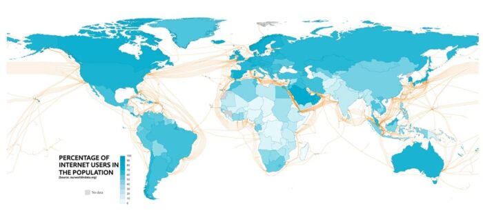
Submarine communication cables form the internet’s system of veins that enables the distribution of data to an increasing number of countries, ever more quickly.
_
Transmission Media in Computer Networks:
Transmission media refers to the physical or wireless communication channel used to carry data signals from one device to another within a computer network. It forms the fundamental pathway through which information is transmitted, ensuring connectivity between networked devices.
The selection of a transmission medium depends on factors such as:
- Transmission distance
- Data transfer speed (bandwidth)
- Susceptibility to interference and noise
- Cost and installation requirements
Based on the nature of the transmission path, transmission media are broadly classified into two main types: guided media and unguided media.
![]()
_
Guided Media:
Guided Media also known as wired or bounded transmission media, refers to transmission media in which data signals are transmitted through a physical path using cables. The signal is confined and guided along a fixed route, providing controlled communication between network devices.
- Uses physical cables to transmit data signals.
- Provides dedicated and well-defined transmission paths.
- Major types of guided media included Twisted Pair Cables, Coaxial Cables and Optical Fiber Cables.
- Offers higher data transmission rates compared to most wireless media.
- Provides better security due to physical connectivity and limited signal leakage.
- Suitable for short to long-distance communication, depending on the cable type used.
Unguided Media:
Unguided media, also known as wireless or Unbounded transmission media, uses electromagnetic waves to transmit data without any physical medium. Signals propagate through free space such as air or vacuum. The main types of unguided media are radio waves, microwaves, and infrared waves.
Features:
- Signals propagate through air or free space
- Less secure due to broadcast nature
- Suitable for long-distance communication
_
Causes of Transmission Impairment:
Transmission impairment refers to the loss or distortion of signals during data transmission, leading to errors or reduced quality in communication. Common causes include signal distortion, attenuation, and noise all of which can affect the clarity and reliability of transmitted data.
Transmission Impairment
- Attenuation: Loss of signal strength as the signal propagates over a transmission medium due to resistance and energy loss. In analog systems, amplifiers are used to increase signal strength, while in digital communication, repeaters or regenerators are used to restore the original signal.
- Distortion: Occurs when the shape of the transmitted signal changes. This typically happens in composite signals where different frequency components travel at different speeds, causing phase shifts and timing differences at the receiver.
- Noise: It refers to unwanted electrical or electromagnetic signals that interfere with the original signal, potentially corrupting data. Common types of noise include thermal noise, induced noise, crosstalk, impulse noise.
_
Factors Considered for Designing the Transmission Media:
- Bandwidth: It refers to the range of frequencies that a transmission medium can support. Higher bandwidth allows higher data transmission rates, assuming other factors such as noise and attenuation remain constant.
- Transmission Impairment: Transmission Impairment occurs when the received signal differs from the transmitted signal. Signal quality will be impacted as a result of transmission impairment.
- Interference: It is the disturbance of a signal caused by the addition of unwanted signals from external sources such as electromagnetic radiation or neighboring channels. It degrades signal clarity and may result in data corruption.
_
Applications of Transmission Media in Computer Networks:
|
Transmission media |
Application |
|
Unshielded Twisted Pair (UTP) |
Local Area Networks (LAN), telephones |
|
Shielded Twisted Pair (STP) |
Industrial networks, environments with high interference |
|
Optical Fiber Cable |
Long-distance communication, internet backbones |
|
Coaxial Cable |
Cable TV, broadband internet, CCTV |
|
Radio |
Wireless communication, AM/FM radio, mobile phones |
|
Infrared |
Remote controls, short-range communication |
|
Microwave |
Satellite communication, radar, long-distance links |
______
______
Fibre optic cables:
In the 1980’s, a new kind of cable was introduced which revolutionised communications. The heart of this new cable is a set of tiny glass fibres, with each fibre about the thickness of a human hair. Computers at each end of a fibre convert sounds (such as voices) and other data to digital pulses. Lasers shoot these pulses of light through the glass fibres of a cable. Computers at the other end convert the pulses back to sounds and data. Most undersea communications cables contain between six and twenty-four glass fibres. Fibre optic cables are often thinner than coaxial cables. Common outside diameters range from 12 to 50 mm (0.5 – 2 inches).
_
Optical Fiber Cable is a guided transmission medium that transmits data in the form of light signals through a glass or plastic core using the principle of total internal reflection. The core is surrounded by a cladding layer with a lower refractive index, which confines the light within the core and enables high-speed, long-distance data transmission. Fibre optic submarine cables carry devices called repeaters, similar to the repeaters of coaxial cable. They are placed at intervals (often 30-80 km or 20-50 miles) along a cable. An insulated copper sheath carries electrical current (sometimes over 10,000 volts!) to power the repeaters. There is particular interest in protecting repeaters, because each one may cost one million US dollars! In some cases, Branching Units connect cables from a trunk to local landing sites.
- Supports very large data volumes at extremely high speeds.
- Can operate in unidirectional or bidirectional communication modes.
- WDM (Wavelength Division Multiplexer) allows multiple light signals to be transmitted simultaneously over a single fiber.
- Widely used where high bandwidth, long distance, and low signal loss are required.
_
An optical fiber is a glass fiber that carries pulses of light that represent data via lasers and optical amplifiers. Some advantages of optical fibers over metal wires are very low transmission loss and immunity to electrical interference. Using dense wave division multiplexing, optical fibers can simultaneously carry multiple streams of data on different wavelengths of light, which greatly increases the rate that data can be sent to up to trillions of bits per second. Optic fibers can be used for long runs of cable carrying very high data rates, and are used for undersea communications cables to interconnect continents.
One disadvantage of fibre optics is that glass is more fragile than copper. Any sharp bend or crushing force may cause fibres to crack and signals to be lost. The minimum bend radius for fibre submarine cables is usually about 1 to 1.5 m (3 – 5 feet). A trawl door, beam trawl or dredge striking a fibre cable can easily render it useless without actually parting it.
__
Are Undersea Cables still the Primary Method of Global Internet Transfer?
Yes. Over 95% of international internet traffic flows through undersea fiber optic cables. These cables are laid on the ocean floor and connect continents like invisible digital highways. As of 2026, there are over 600 active submarine cables, spanning more than 1.5 million kilometers, delivering petabytes of data every second. Submarine cables use light signals transmitted through fiber optics to transfer data at nearly the speed of light. These signals are amplified every 50–100 km using repeaters to maintain signal strength. Each cable typically contains multiple pairs of fibers, and each pair can carry multiple terabits of data per second.
_____
_____
The internet may feel wireless, but behind the scenes lies a vast, complex, and mostly physical infrastructure that connects the entire world. One of the most fascinating aspects is how the internet connects between countries and continents—through undersea cables, satellite links, and massive data centers spread across the globe.
The backbone of the internet between countries and continents consists of:
- Submarine (undersea) fiber optic cables
- Landing stations
- Internet Exchange Points (IXPs)
- Satellites (as backup or in remote areas)
- Network routers and peering agreements
These components ensure that data flows efficiently from your home network in India to a server in California, Japan, or anywhere else on Earth.
_
What happens when you access a Website Overseas?
Here’s a simplified path your data follows when visiting a website hosted in another country:
-1. Your device (mobile/laptop) sends a request through your local Wi-Fi/router.
-2. The signal travels through your ISP’s data center.
-3. It passes through national internet infrastructure to reach a cable landing station.
-4. The request travels through an undersea cable to another continent.
-5. It reaches a landing station in the destination country.
-6. The data is routed to the server hosting the website.
-7. The server responds, and the process happens in reverse.
_
Flowchart: How Data travels Internationally over the Internet:
[Your Device]
↓
[Local Router/Wi-Fi]
↓
[ISP Network]
↓
[National Backbone Router]
↓
[Cable Landing Station]
↓
[Submarine Fiber Optic Cable]
↓
[Landing Station in Destination Country]
↓
[Data Center/Server]
↓
[Response Sent Back Through Same Route]
This is a simplified version, but it accurately reflects the core steps in international internet connectivity.
_
Undersea cables constitute a critical component of the internet delivery chain, serving as an integral part of the first mile infrastructure that facilitates internet access to a country (see figure below). They connect and transmit data to the middle mile—terrestrial networks, such as national backbones. These subsequently link to the last mile, facilitating connections to the end user via mobile or fixed broadband services. The significance of undersea cables cannot be underestimated and necessitates strong governance (considered part of the invisible mile) and management to guarantee that internet ecosystem flourishes and delivers the anticipated digital benefits.
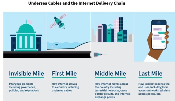
Figure above shows undersea cables and internet delivery chain.
_
Role of Satellites in Internet Connectivity:
Satellites like those in the Starlink constellation do provide internet access but account for less than 1% of global data traffic. They’re crucial for remote locations, ships, airplanes, and as backup options during submarine cable outages.
Internet Exchange Points (IXPs):
IXPs are physical locations where multiple ISPs and networks connect and share traffic. Major cities often have several IXPs to reduce latency and improve bandwidth efficiency. Without IXPs, your internet data would take longer and cost more to route between networks.
__
Risks to Global Internet Connectivity:
Yes, although the infrastructure is resilient, threats include:
- Submarine cable cuts (from fishing, anchors, earthquakes)
- Cyberattacks on core routers or IXPs
- Political controls over national infrastructure
- Dependence on major tech hubs like the U.S., Europe, and China
Global redundancy (multiple cables and ISPs) helps minimize outages.
_
Key Elements of Global Internet Connectivity:
|
Component |
Purpose |
Example |
|
Submarine Fiber Cables |
Transmit data between continents |
SEA-ME-WE 6, Google Equiano |
|
Cable Landing Stations |
Termination points for undersea cables |
Chennai (India), Marseille (France) |
|
Internet Exchange Points |
Interconnect multiple networks |
DE-CIX (Germany), LINX (UK), NIXI (India) |
|
National Backbone Routers |
Route traffic within countries |
BSNL, Airtel, Tata Communications routers |
|
Satellites |
Provide backup or remote internet access |
Starlink, OneWeb, HughesNet |
|
Peering Agreements |
Govern data sharing between ISPs |
Tier-1 ISPs like AT&T, Tata, NTT |
While the internet may feel instantaneous, it depends on an intricate global system of cables, routers, landing stations, and satellites. Each time you stream a video, send a message, or check your email across borders, you’re using this incredible infrastructure. As global demand increases, more cables and technologies are being deployed to ensure a faster, more resilient internet for the world.
______
______
Section-4
Science of optical fiber transmission and its evolution:
_
All ways of expressing information (i.e. voice, video, text, data) use physical system, for example, spoken words are conveyed by air pressure fluctuations. Information cannot exist without physical representation. Information, the 1’s and 0’s of classical computers, must inevitably be recorded by some physical system – be it paper or silicon. The information travels from one computer to another via radio waves (wireless) or via pulses of light or electricity (wired), and the transfer needs physical system, be it electromagnetic waves or electrons. Radio waves travel at nearly the speed of light in air, whereas light in fiber optic cable travels at ~67% of the speed of light due to the refractive index of glass. Radio waves cannot be transmitted through fiber-optics. RF cables are designed to transmit high-frequency alternating current (AC) signals, typically ranging from I MHz to over 67 GHz, well above the standard 50/60 Hz power frequency. They are commonly used for frequencies from several hundred MHz to tens of GHz for applications like communications, data transmission, and broadcasting. Radio frequency (RF) signals in coaxial cables travel at 50% to 90% of the speed of light.
_
Why radio waves are not transmitted in optical fibers?
Fiber optic is a waveguide. Every waveguide has a critical “cutoff frequency”, below which conventional wave propagation ceases & a phaseless high attenuation mode occurs instead. The cutoff frequency is when the narrowest dimension of the waveguide is less than 1/4th wavelength of the electromagnetic energy. For fibers with core diameters on the orders of microns, “radio waves” even in multi-GHz are still “too large” to fit into the waveguide structure. Unlike visible or infrared light, which travel via total internal reflection, low-frequency radio waves cannot propagate, and the dielectric glass material is ineffective for conducting radio frequencies, which would instead be absorbed or skip past the waveguide entirely.
Laser light is used in fiber optics because it is monochromatic (single wavelength), coherent, and highly directional, allowing for, much higher speed data transmission over longer distances. Lasers provide high-intensity light that experiences minimal signal attenuation (loss of power) and enables high-bandwidth, long-haul communication compared to other light sources like LEDs.
_
Wired and wireless network:
Signals can be sent via radio waves (wireless), via RF current in RF cable (wired) and via light in fiber cables (wired). RF stands for “Radio Frequency” and has become a catch-all term for certain wired communications and a large (spectral) range of wirelessly transmitted waves. Radio frequency (RF) signals carrying information (voice, video, data) can be transmitted via radio waves (2G, 3G, 4G, 5G and wi-fi), via RF current in RF cable (coaxial cable, twin-lead cable) and via light in fiber cables (optical fibers). Radio over fiber (RoF) or RF over fiber (RFoF) refers to a technology whereby light is modulated by a radio frequency signal and transmitted over an optical fiber link. Main technical advantages of using fiber optical links are lower transmission losses and reduced sensitivity to noise and electromagnetic interference compared to all-electrical signal transmission.
_
A bit is the smallest unit of digital information and can have a value of either 0 or 1. Data transfer rate(speed) of internet is usually in bits per second. The speed of transmission of data from computer to computer through wireless technology (air) is the same as the speed of radio waves (speed of light) which is 300,000 kilometers per second. The internet data speed Kbps or Mbps refers to the speed of the data converted into radio waves and not the speed of data when traveling through the air.
Internet speed measurement:
Kbps = kilobits per second = 1,000 bits per second
Mbps = megabits per second = 1,000 Kbps
Gbps = gigabit per second = 1,000 Mbps
Tbps = terabit per second = 1,000 Gbps
Terabit per second (Tbps) is a measure of data transfer speed, indicating that 1 trillion bits of data are transmitted each second. It is commonly used to describe the capacity of high-speed networks, such as fiber-optic connections.
Please note that internet speed and throughput of communication system are measured in bits per second while bandwidth is measured in Hertz; although the term bandwidth is also used for network speed. Larger bandwidth in Hertz can carry large amount of information (high data rate in bits per second).
_
As today’s cellular providers attempt to deliver high quality, low latency video and multimedia applications for wireless devices, they are limited to a carrier frequency spectrum ranging between 700 MHz and 2.6 GHz. Carrier frequency is the basic operative frequency of radio wave that carries information (voice, video, data) from one place to another place by modulation. To transmit information on a carrier wave, we distort it slightly, those distortions carrying the information we want. For traditional radio, an actual audio signal is encoded on the carrier; for internet signals, the distortions carry the binary 1’s and 0’s of the digitized information. A modulated carrier radio wave, carrying an information signal, occupies a range of frequencies. The information (modulation) in a radio signal is usually concentrated in narrow frequency bands called sidebands just above and below the carrier frequency. The width in hertz of the frequency range that the radio signal occupies, the highest frequency minus the lowest frequency, is called its bandwidth (BW). A given amount of bandwidth can carry the same amount of information (data rate in bits per second) regardless of where the carrier frequency is located all else being equal, so bandwidth is a measure of information-carrying capacity. For example, a 3 kHz bandwidth can carry a telephone conversation no matter whether carrier frequency is 900 MHz or 1800 MHz. The data rate of the information (modulation signal) being sent depends on bandwidth and the spectral efficiency of the modulation method used; how much data it can transmit in each kilohertz of bandwidth. Spectral efficiency is expressed in bits per second per hertz (bps/Hz).
_
Higher carrier wave frequency carries more modulation than lower carrier wave frequency because higher frequency means there are more cycles per second available to fit information signal. So higher frequency carrier wave carries more information than lower carrier wave frequency. If the allowable frequency range were 100kHz to 200kHz (spectrum bandwidth 100KHz), and we needed 20kHz channels, the most we can get is 5 channels. If the allowable frequency range were 100MHz to 200MHz (spectrum bandwidth 100 MHz), the maximum number of 20kHzs channels we could get is 5,000 channels. So higher the frequency range available, more information can be transmitted. Fiber-optic cables transmit light with wavelengths range from 1300 nm to 1600 nm – the corresponding frequencies are above 100 THz, which is why they can support very high data rates. The standard for long distance communication (The C-band) is around 1550nm, which is approximately 193,000GHz (193 THz).
______
Two meanings of the word bandwidth:
Those of us in computer networking have stolen the term “bandwidth” from the radio engineers and now we misuse it to mean “throughput” in the context of computer networking. To a radio engineer, bandwidth is just one of many factors in throughput (modulation scheme is another major factor). To a computer network engineer, “bandwidth” is pretty much just a synonym for throughput. In computing, bandwidth is the maximum rate of data transfer across a given path measured in bits per second. This definition of bandwidth is in contrast to the field of signal processing, wireless communications, modem data transmission, digital communications, and electronics, in which bandwidth is used to refer to analog signal bandwidth measured in hertz, meaning the frequency range between lowest and highest attainable frequency while meeting a well-defined impairment level in signal power. Bandwidth is the range of frequencies associated with signal that can pass through a medium. The transmitted signal can be voice, text, video and other data. Different signal has different range of frequencies. It is a measure of the frequency range that is occupied by a modulated signal (carrier wave + information).
______
Bandwidth in Core Networks:
An optical fiber acts as a simple “light pipe,” slightly thicker than a human hair, designed to transmit light between the two ends of the cable. Metal wires are also used but are subject to higher signal loss, electromagnetic interference, and higher lifetime maintenance costs. Chances are, your packets will travel over both types of cable, but for any long-distance hops, they will be transmitted over a fiber-optic link. Optical fibers have a distinct advantage when it comes to bandwidth because each fiber can carry many different wavelengths (channels) of light through a process known as wavelength-division multiplexing (WDM). Hence, the total bandwidth of a fiber link is the multiple of per-channel data rate and the number of multiplexed channels. As of early 2010, researchers have been able to multiplex over 400 wavelengths with the peak capacity of 171 Gbit/s per channel, which translates to over 70 Tbit/s of total bandwidth for a single fiber link! We would need thousands of copper wire (electrical) links to match this throughput. Not surprisingly, most long-distance hops, such as subsea data transmission between continents, is now done over fiber-optic links. Each cable carries several strands of fiber (four strands is a common number), which translates into bandwidth capacity in hundreds of terabits per second for each cable.
______
Radio wave attributes:
A radio wave is a type of electromagnetic signal designed to carry information through the air over relatively long distances. Sometimes radio waves are referred to as radio frequency (RF) signals. Radio waves have been in use for many years. They provide the means for carrying music to FM radios and video to televisions. In addition, radio waves are the primary means for carrying data over a wireless network. A radio wave has amplitude, frequency, and phase elements. These attributes may be varied in time to represent information.
-1. Amplitude:
The amplitude of a radio wave indicates its strength. The measure for amplitude is generally power, which is analogous to the amount of effort a person needs to exert to ride a bicycle over a specific distance. Similarly, power in terms of electromagnetic signals represents the amount of energy necessary to push the signal over a particular distance. As the power increases, so does the range.
Radio waves have amplitudes with units of watts, which represent the amount of power in the signal. Watts have linear characteristics that follow mathematical relationships we are all very familiar with. For example, the result of doubling 10 milliwatts (mW) is 20 mW.
As an alternative, it is possible to use dBm units (decibels referenced to 1 mW) to represent the amplitude of radio waves. The dBm increment is based on the decibel, a logarithmic measure of relative power.
Suppose a signal has a power level of P mW. Then the signal strength in dBm, symbolized S dBm, is:
S dBm = 10 log10 P
A 1-mW signal has a level of 0 dBm. Signals weaker than 1 mW have negative dBm values; signals stronger than 1 mW have positive dBm values.
-2. Frequency & wavelength:
There are few properties of radio waves which make it distinct and usable. The first consideration is frequency. The frequency of the wave is the number of the cycles of a sine wave completed in one second. In the case of moving waves, such as radio waves, the frequency can be thought as the number of cycles of the wave that pass a given point in one second. The term hertz (Hz) was designated for use in lieu of the term cycles per second when referring to the frequency of radio waves. Hertz refer to the number of occurrences that take place in one second.
802.11 WLANs (wi-fi) use radio waves having frequencies of 2.4 GHz and 5 GHz, which means that the signal includes 2,400,000,000 cycles per second and 5,000,000,000 cycles per second, respectively. Signals operating at these frequencies are still too low for humans to see. Thus, radio waves are not seen by humans.
The frequency impacts the propagation of radio waves. Theoretically, higher-frequency signals propagate over a shorter range than lower-frequency signals. In practice, however, the range of different frequency signals might be the same, or higher-frequency signals might propagate farther than lower-frequency signals. For example, a 5-GHz signal transmitted at a higher transmit power might go farther than a 2.4-GHz signal transmitted at a lower power, especially if electrical noise in the area impacts the 5-GHz part of the radio spectrum less than the 2.4-GHz portion of the spectrum (which is generally the case).
In free space the propagation speed of radio waves is the same as that of light, at approximately 300,000 km per second. The speed falls slightly when passing through a conductor such as an antenna or cable.
The wave length L of radio waves is as follows; If the frequency of the radio wave is F, and the speed of the radio wave in a vacuum is C, then
L = C / F
As the speed of radio waves in air is about 300,000 km/sec (about 300,000,000 meter/sec), at 700 MHz the wave length L is 300,000,000/700,000,000 = 0.428 meter
-3. Phase:
The phase of a radio wave corresponds to how far the signal is offset from a reference point (such as a particular time or another signal). By convention, each cycle of the signal spans 360 degrees. For example, a signal might have a phase shift of 90 degrees, which means that the offset amount is one-quarter (90/360 = 1/4) of the signal.
______
Modulation:
Modulation is to vary the amplitude, frequency or phase of a carrier radio frequency wave in accordance with the information to be conveyed. A carrier wave is a pure wave of constant frequency, a bit like a sine wave. By itself it doesn’t carry much information that we can relate to (such as speech or data). To include speech information or data information, another wave needs to be imposed, called an input signal, on top of the carrier wave. This process of imposing an input signal onto a carrier wave is called modulation. In other words, modulation changes the shape of a carrier wave to somehow encode the speech or data information that we were interested in carrying. Modulation is like hiding a code inside the carrier wave. Mixing of low frequency information signal carrying voice, video and data with high frequency carrier signal is called modulation. It allows low-frequency baseband signals (which cannot travel far on their own) to be transmitted over long distances by giving them a “ride” on a high-frequency carrier wave.
_______
Bandwidth in Hertz to data speed in bits per second:
Each and every type of wireless technology has its own set of constraints and limitations. However, regardless of the specific wireless technology in use, all communication methods have a maximum channel capacity, which is determined by the same underlying principles. In fact, Claude E. Shannon gave us an exact mathematical model (Channel capacity is the maximum information rate) to determine channel capacity, regardless of the technology in use. The Shannon-Hartley formula, C = B X log2 (1 + S/N), calculates the maximum theoretical data rate (channel capacity C in bits per second) for a communication channel with bandwidth B (Hz) in the presence of noise, given a signal-to-noise ratio (S/N). It represents the fundamental limit of reliable communication.
Although somewhat simplified, this formula captures all the essential insights we need to understand the performance of most wireless networks. Regardless of the name, acronym, or the revision number of the specification, the two fundamental constraints on achievable data rates are the amount of available bandwidth and the signal power between the receiver and the sender.
As Shannon’s model shows, the overall channel bit-rate is directly proportional to the assigned range. Hence, all else being equal, a doubling in available frequency range will double the data rate—e.g., going from 20 to 40 MHz of bandwidth can double the channel data rate, which is exactly how 802.11n is improving its performance over earlier Wi-Fi standards!
_______
Radio waves are always analog:
The method for imposing on a radio wave some sort of data is known as the method of modulating the radio wave so that the radio wave can “carry” the information. Information can be modulated in many ways. Digital information and analog information can be imposed on a radio wave. Interestingly, digital information is an encoding of information using some sort of bit (on or off) representation. Sometimes, that on and off nature of digital information can be confused with a radio wave, since a radio wave alternates between zero and the maximum amplitude (in either the positive or negative polarity). But, radio waves, no matter how complex the modulation of the radio wave, are fundamentally analog. When your original data is analog (e.g. your speech), analog-to-digital converter makes it digital data. This digital data is then transmitted over analog radio waves by encoding digital data into analog signal. Remember radio waves are always analog and therefore they can only carry analog signals; all digital data of voice, video and text must be converted into analog signals, the process known as digital modulation.
______
Light waves in fiber optical cable are always analog:
The transceiver converts the electrical signals into light pulses. These light pulses are then sent through the fiber optic cable. The light pulses travel through the fiber cable and are converted back into electrical signals at the other end by another transceiver. For fiber optics, a laser emitting diode converts the electrical signal to light and light sensing diode coverts it back at the other end. Information such as voice, video, or data is converted into light signals through modulation techniques. Modulation can be achieved by rapidly turning the light on and off (digital modulation) or varying the property of the light (analog modulation). No matter the modulation techniques, light waves in fiber optic cables are always analog.
-Data rides on light by modulating amplitude, phase, frequency, and polarization of an optical carrier signal.
-External modulators + coherent detection + DSP enable very high bitrates and spectral efficiency.
-Multiplexing (WDM, PDM, TDM) and optical amplification scale capacity over long distances, while dispersion, nonlinearities, and noise are managed by DSP and optical design.
______
Spectral efficiency:
Since frequency spectrum is limited, it has to be utilized efficiently. A given bandwidth is said to be used effectively if maximum information can be transmitted over it. The term Spectral Efficiency is used to describe the rate of information being transmitted over a given bandwidth in specific communication systems. Spectral Efficiency may also be called bandwidth efficiency. If a specific communication system uses one kilo hertz of bandwidth to transmit 1,000 bits per second, then it has a spectral efficiency or bandwidth efficiency of 1 (bit/s)/Hz. Spectral efficiency (bits/s/Hz) measures how efficiently bandwidth is used to transmit data, while SNR (signal-to-noise ratio) measures signal quality against noise. Higher SNR enables higher spectral efficiency by allowing more complex, dense modulation schemes (like QAM), enabling faster, more reliable data rates within the same channel bandwidth.
The spectral efficiency (that is the number of “bits” that we can code per single Hz) has reached its peak with OFMD and 64/256 QAM modulation used in the 4G system. 5G shows incredible spectral efficiency far beyond Shannon limit, current record is 145.6 b/s/Hz (with 256 QAM), a sensational result given that the usual spectral efficiency is around 2.5 b/s/Hz. In 5G, the communications take place using several antennas in parallel, 128 in this case. In this way rather than using a single communication “channel” we use many of them (MIMO: Multiple Input Multiple Output) and the array of antennas coupled with a software that detects and decodes the signal allows the resolution of the interference resulting from multiple channels. This increased efficiency, however, is not a 5G property, it is already being used today in Wi-Fi communications (two antennas are normally used) and in the 4G. The constraints are given first by the available processing power (the more processing power is available, the more parallel channels you can process and therefore solve the interference generated by n-1 channels provided you can have the signals from n antennas), and second by the topology architecture of the antennas array. The antennas need to be separated one another by at least half a wavelength (that is why you see Wi-Fi antennas shaped like horns, separated by some 10 cm, at the two edges of the box). The higher the frequency, the closer the antennas can be. The use of millimeter waves, 50GHz (at 50GHz the wavelength is 6mm) and beyond, allow us create smart antennas array, massive MIMO.
_____
_____
The dB of optical fiber:
In the case of fiber optic cable, we are comparing the power injected at one end of the cable to the power received at the other end. If the optical power injected was -20 dBm and the power received at the other end -21 dBm, then the optical loss of the link would be -20 – (-21) = 1 dB.
The units dB and dBm stands for decibel and decibel milliwatt, respectively.
A measurement of 0 dBm using an optical power meter indicates 1 milliWatt of power.
The unit dBm refers to the power level at the transmitter and receiver ends of the cable. Or, it is appropriate to say the power injected or power received in the fiber optic cables is expressed in dBm. The unit dB expresses the difference between two dBm values.
The optical power in fiber optic cables is measured in dBm, whereas optical power loss is measured in dB. It is possible to express optical power and power loss in the same unit, but the general practice is to use different units. The difference between dB and dBm in fiber optics is a common discussion point.
_
Optical Power Loss:
When the optical power travels from the transmitter to the receiver, light energy gets lost due to scattering and absorption. The fiber loss, fiber optic connector loss, and losses in splices can reduce the light levels below acceptable limits. That is why the optical power loss calculation is important when you are looking for reliable fiber-optic communication. It also determines how long the fiber optic cable can be extended without disturbing communications. The optical fiber loss is usually expressed in dB. The unit dB expresses the difference between two dBm values.
dB = 10 log (measured power/reference power)
The difference between the transmitter power (dBm) and receiver power (dBm) in fiber optic cables gives the optical power loss, which is expressed in dB. Even though the loss is negative, we express it as a positive value followed by dB. This is done because “loss” is defined as a positive magnitude representing the amount of signal power reduced (attenuation) in fields like fiber optics and electronics, rather than the mathematical result of the equation, to avoid confusion. When the optical power level is halved or doubled, there is a 3 dB decrease or increase in the optical strength.
Both dBm and dB are in logarithmic scales and are non-linear measurement units. The dBm measurement is relative to milliwatts. The dBm values can be converted into watts, whereas this conversion is not possible with dB.
It is important to understand the difference between dB and dBm in fiber optic measurements when working on optical communication systems. Optical power and optical power loss are common in all optically energized systems.
_
Optical fiber losses, or attenuation, refer to the reduction in signal strength (power) as light travels through the cable, measured in decibels (dB). Major losses are caused by absorption (impurities), scattering (material imperfections), bending (structural, macrobending / microbending), and connection losses (splices, connectors).
OFC loss (attenuation) per km depends on fiber type and wavelength, typically ranging from 0.2 dB/km to 0.5 dB/km for single-mode (1550/1310nm) and 2.5 dB/km to 3.5 dB/km for multimode (850nm).
______
______
Optical windows:
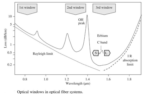
Optical windows in fiber communication are specific wavelength bands (850nm, 1310nm, 1550nm) where silica fiber exhibits minimal attenuation and dispersion. These windows are optimized for low-loss transmission: the 1st (850 nm) for short-range; 2nd (1310 nm) for low dispersion; and 3rd (1550 nm) for long-haul, high-capacity communication using optical amplifiers.
_
Summary Table of Optical Windows:
|
Window |
Wavelength |
Characteristics |
Main Application |
|
1st |
850 nm |
High loss, High dispersion |
Short-distance/LANs |
|
2nd |
1310 nm |
Low loss, Zero dispersion |
Metro networks |
|
3rd |
1550 nm |
Lowest loss, High dispersion |
Long-haul, DWDM |
These windows are heavily influenced by the scattering and absorption of the light by the silica fiber, with the first window, in particular, seeing higher scattering loss.
_____
Optical Communication Band:
Fiber-optic communication is mainly conducted in the wavelength region where optical fibers have small transmission loss. This low-loss wavelength region ranges from 1260 nm to 1625 nm, and is divided into five wavelength bands referred to as the O-, E-, S-, C- and L-bands, as shown in Figure below.
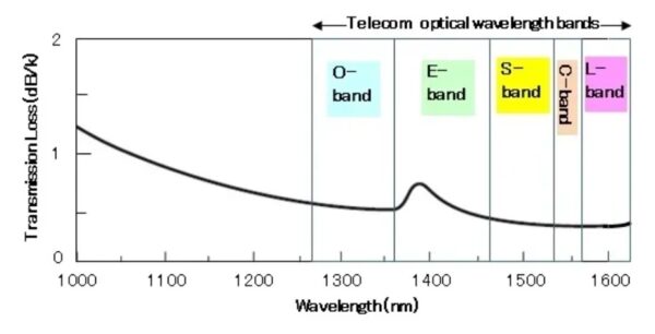
Figure above shows transmission loss of silica fiber and optical communication wavelength bands.
Among these five bands, the O-band (original band: 1260-1360 nm) was historically the first wavelength band used for optical communication, because signal distortion (due to chromatic dispersion) is minimum. It was also because optical fibers produced in the mid 1970s showed its lowest loss near the O-band.
Today optical fibers show its lowest loss in the C-band, and thus is commonly used in many metro, long-haul, ultra-long-haul, and submarine optical transmission systems combined with the WDM and EDFA technologies.
The L-band is the second lowest-loss wavelength band, and is a popular choice when the use of the C-band is not sufficient to meet the bandwidth demand. The same WDM and EDFA technologies can be applied to the L-band. Repeatered C+L-band WDM transmission is now commercially feasible, and is employed even for transoceanic submarine transmission systems.
______
Modem:
A modulator-demodulator, commonly referred to as a modem, is a computer hardware device that converts data from a digital format into a format suitable for an analog transmission medium such as telephone or radio. A modem transmits data by modulating one or more carrier wave signals to encode digital information, while the receiver demodulates the signal to recreate the original digital information. The goal is to produce a signal that can be transmitted easily and decoded reliably. Modems can be used with almost any means of transmitting analog signals, from LEDs to radio. Today, modems are ubiquitous and largely invisible, included in almost every mobile computing device in one form or another, and generally capable of speeds on the order of tens or hundreds of megabytes per second.
Modems are frequently classified by the maximum amount of data they can send in a given unit of time, usually expressed in bits per second (bit/s, sometimes abbreviated “bps”) or rarely in bytes per second (B/s). Modern broadband modem speeds are typically expressed in megabits per second (Mbit/s).
Historically, modems were often classified by their symbol rate, measured in baud. The baud unit denotes symbols per second, or the number of times per second the modem sends a new signal. For example, the ITU-T V.21 standard used audio frequency-shift keying with two possible frequencies, corresponding to two distinct symbols (or one bit per symbol), to carry 300 bits per second using 300 baud. By contrast, the original ITU-T V.22 standard, which could transmit and receive four distinct symbols (two bits per symbol), transmitted 1,200 bits by sending 600 symbols per second (600 baud) using phase-shift keying.
______
Baud rate:
Baud rate measures the number of signal changes (symbols) per second in a communication channel, determining the speed of serial data transfer. Commonly used in devices like UART/Arduino (e.g., 9600, 115200), it represents the communication frequency. While often equal to bits per second (bps) in simple systems, higher-level modulation can make the actual bit rate much higher than the baud rate.
Key Aspects of Baud Rate:
- Definition: The rate at which the state of a signal changes (voltage, frequency, or phase) per second, measured in Baud (Bd).
- Baud vs. Bit Rate: Baud rate is the symbol rate, while bit rate is the data speed (baud = signal changes/second, bit rate = baud x bit per symbol)
- Common Speeds: Typical baud rates include 9600, 19200, 38400, 57600, and 115200.
- Significance: Higher baud rates allow faster data transmission but require shorter, higher-quality cables to maintain signal integrity.
- Application: Essential for matching communication settings between devices (e.g., computer to microcontroller), commonly used in UART, RS-232, and modems.
- Calculation:
Baud rate = signal elements/total time (s)
Baud rate = bit rate /bits per symbol
For example, if a system uses a baud rate of 9600, it means 9600 signal changes occur per second.
______
OSNR:
In subsea optical transmission, Optical Signal-to-Noise Ratio (OSNR) is the ratio of optical signal power to noise power, describing the relative noise introduced by the repeaters along the subsea line, as a result of Amplified Spontaneous Emission (ASE), within a specific bandwidth, serving as a critical metric for performance in fiber-optic networks. A higher OSNR indicates better signal quality, lower Bit Error Rate (BER), and longer signal reach.
- Definition: Measures how far the signal “stands out” from the noise, often expressed in decibels (dB). An OSNR reading is usually stated as dB/0.1 nm to indicate the bandwidth at which the noise was measured.
- Importance: It is crucial for determining signal quality in Dense Wavelength Division Multiplexing (DWDM) networks, as it indicates the maximum number of amplified fiber spans a signal can travel before requiring regeneration.
- Noise Sources: Active sources (lasers, amplifiers) and passive sources (connectors, splices, fiber nonlinearities) both contribute to reducing the OSNR.
- Measurement: Usually measured using an Optical Spectrum Analyzer (OSA) to analyze the signal power relative to the noise pedestal.
Methods to Improve OSNR:
- Increase Input Power: Raising the optical signal power at the amplifier input.
- Reduce Amplifier Spacing: Minimizing the distance between amplifiers reduces the accumulation of noise.
- Component Optimization: Using lower-noise amplifiers and higher-quality, low-loss fiber.
- Use Proper Pumping Schemes: Implementing optimal optical pumping to maximize gain while minimizing noise generation.
______
Fiber optic transponder:
In optical fiber communications, a transponder is the element that sends and receives the optical signal from a fiber. A transponder is typically characterized by its data rate and the maximum distance the signal can travel.
The difference between a fiber optic transponder and transceiver:
A transponder and transceiver are both functionally similar devices that convert a full-duplex electrical signal in a full-duplex optical signal. The difference between the two being that transceivers interface electrically with the host system using a serial interface, whereas transponders use a parallel interface to do so.
So transponders provide easier to handle lower-rate parallel signals, but are bulkier and consume more power than transceivers.
Major functions of a fiber optic transponder include:
- Electrical and optical signals conversions
- Serialization and deserialization
- Control and monitoring
Multi-rate, bidirectional fiber transponders convert short-reach 10 Gb/s and 40 Gb/s optical signals to long-reach, single-mode dense wavelength division multiplexing (DWDM) optical interfaces.
Supporting dense wavelength multiplexing schemes, fiber optic transponders can expand the useable bandwidth of a single optical fiber to over 300 Gb/s.
______
Optical Modulation:
Optical modulation changes how light waves act to carry information. This lets devices send lots of data fast and without mistakes. This process dynamically alters properties of an optical carrier wave—such as amplitude, phase, frequency, or polarization—to embed data. Its inverse, demodulation, extracts this information at the receiving end. Today’s networks use optical modulation to make data move faster. QPSK [Quadrature Phase Shift Keying] and BPSK [Binary Phase Shift Keying], sometimes called PRK [Phase Reversal Keying] or 2PSK, are the long distance modulation techniques. 16QAM [Quadrature Amplitude Modulation] would be used on a shorter length subsea cable system, and they’re bringing in 8QAM technology to fit in between 16QAM and BPSK. These methods let many bits travel together in the same space. People want faster internet because of 5G, cloud computing, and new digital tools. This has made the optical modulators market grow quickly. New improvements in optical modulation have doubled how much fiber optic cables can carry at important times. This helps many areas, like telecommunications and healthcare.
There are two main ways to do optical modulation. Direct modulation changes the current going to a laser, which then changes the light. This way is simple but works best for slower data speeds. External modulation uses special modulators to change the light after it leaves the laser. These modulators can work at higher speeds and give more control. Some common modulators are electro-optic modulators, which use electric fields to change the phase of light, and electro-absorption modulators, which block or let light pass like a shutter.
Optical modulation in communication is the process of mapping information (digital or analog) onto a light wave (laser/LED) by varying its characteristics—amplitude, phase, frequency, or polarization—for transmission through optical fiber or free space. It enables high-speed data transfer by converting electrical signals into light signals, primarily using direct or external modulation techniques.
_
Any optical communication system consists of three main parts, transmitter, medium and receiver. A transmitter is also divided into two basic categories, Laser diode and LED (light emitting diode). Laser diode is used for single mode fibers and LED is used for multi modal fiber. Similarly, a receiver consists of three components: a detector, an amplifier and a demodulator. Each component has its own job, so a detector converts an optical signal into an electrical one and then an amplifier regenerates the strength of this signal and at last a demodulator extracts the original electrical signal.
______
Chromatic dispersion:
As the carrier frequency of the signal increased, coupled with long cable runs, the factor of chromatic dispersion became more critical. Chromatic dispersion (CD) is a phenomenon in fiber optics where different wavelengths (colors) of light travel at different speeds through a fiber, causing signal pulses to spread out and overlap over long distances. This distortion reduces data rates, as transmitted light pulses (bits) merge, making them harder to distinguish at the receiver. It arises from two main sources: material dispersion (refractive index depends on wavelength) and waveguide dispersion (light speed depends on the physical structure of the fiber). It is a major limiting factor in high-speed, long-haul fiber optic communication, causing inter-symbol interference (ISI). It is typically measured in picoseconds per nanometer-kilometer [ps/(nm-km)] and measured using techniques like the phase-shift method. Techniques to counteract CD include using Dispersion Compensating Fiber (DCF), which has an opposite dispersion sign to standard fiber, or using Fiber Bragg Grating (FBG) compensators. It’s by no means a perfect solution, and while it’s possible to design a dispersion compensation system that compensates for dispersion at the middle frequency of the C-band, the edge frequencies will still show significant chromatic dispersion when using long cable runs.
Chromatic dispersion can be thought of as the broadening of a pulse, similar to how white light disperses into colors through a prism, where higher frequencies (shorter wavelengths) generally travel at different speeds than lower frequencies.
_______
Nonlinearities:
Nonlinearities in optical fibers occur when high-intensity light alters the fibre’s refractive index or causes scattering, leading to signal distortion, spectral broadening, and crosstalk. These intensity-dependent effects include the Kerr effect (SPM, XPM, FWM) and inelastic scattering (SRS, SBS), significantly limiting capacity in long-haul, high-power WDM systems. Fiber nonlinearity prevents channel capacity from approaching the Shannon limit, especially when signal power is high and/or transmission distance is long.
______
Optical repeaters:
Optical repeaters are perhaps a misnomer these days. Earlier electrical repeaters operated in a conventional repeating mode, using a receiver to convert the input analogue signal into a digital signal, and then re-encoding the data into an analogue signal and injecting it into the next cable segment.
These days optical cable repeaters are photon amplifiers that operate at full gain at the bottom of the ocean for an anticipated service life of 25 years. Light (at 980nm or 1480nm) is pumped into a relatively short erbium-doped fibre segment. The erbium ions cause an incoming light stream in the region around 1550nm to be amplified. The pump energy causes the erbium ions to enter a higher energy state, and when stimulated by a signal photon, the ion will decay back to a lower energy level, emitting a photon at the energy level of the stimulated state, but with a light frequency equal to the triggering incoming signal. This emitted amplified signal conveniently shares the same direction and phase as the incoming light signal. These are called Erbium Doped Fibre Amplifier (EDFA) units.
This has been revolutionary for subsea cables. The entire wet segment, including the repeaters, are entirely agnostic with respect to the carrier signal. The number of lit wavelengths, the signal encoding and decoding, and the entire cable capacity is now dependent on the equipment at the cable stations at each end of the cable. This has extended the service life of optical systems, where additional capacity can be scavenged from deployed cables by placing new technology in the cable stations at either end, leaving the wet segment unaltered. The wet plant is also agnostic with respect to the cable carrying capacity in these all-optical systems.
The subsea optical repeater units are designed to operate for the entire operational life of the cable without any further intervention. The design includes an element of redundancy in that if a repeater fails then the cable capacity may be degraded to some extent but will still operate with viable capacity.
The EDFA units have a bias in amplification across the operational frequency range and it’s necessary to add a passive filter to the amplified signal to generate a flatter power spectrum. This allows the cumulative sum of these in-line amplifiers to produce an outcome that maximizes signal performance for the entire spectrum of the band used on the cable. Over extended distances, this is still insufficient, and cables may also use active units, called ‘Gain Equalization Units’. The number, spacing and equalization settings used in these units are part of the customized design of each cable system.
In terrestrial systems, amplifier control can be managed dynamically, and as channels are added or removed the amplifiers can be reconfigured to produce an optimal gain. Subsea amplifiers have no such dynamic control, and they are set to gain saturation, or always on ‘maximum’. To avoid overdriving the lit channels, all unused spectrum channels are occupied by an ‘idler’ signal.
Repeaters are a significant cost component of the total cable cost, and there is a compromise between a ‘close’ spacing of repeaters, every 60km or so, or stretching the inter-repeater distance to 100km and making significant savings in the number of repeaters in the system. On balance it is the case that the more you are prepared to spend on the cable system the higher the cable carrying capacity.
The observation here is that a submarine cable is not built by assembling standard components and connecting them using a consistent set of engineering design rules, but by customizing each component within a bespoke design to produce a system which is built to optimize its service outcomes for the particular environment where the cable is to be deployed. In many respects, every undersea cable project is built from scratch.
_______
_______
Structure of Fiber Optic Cable:
Fiber optic cable is structured in a way that allows light signal to be transmitted perfectly and as fast as the light speed can run without bending, which causes the signal light to be wasted by any single sharp pending or breaking of glass. Thus, it has been constructed to be flexible and strong using several elements. It consists of a core, cladding, coating buffer, strength member and outer jacket. First of all, core is the pulp of data transmission that carries optical data signals from the light source to a receiving device as a physical medium. It is made of a combination of silica and Germania. The volume of light that the cable can carry depends on its diameter, so a larger diameter width means carrying more lights. Second, cladding is surrounding the core as a boundary containing light waves and keeping light stable in the core because it has less refraction than the core, it is made of pure silica. Third, coating is made of plastic which layer both core and gladding to protect and reinforce them. Forth, strengthening is constructed for the purpose of preventing damage during installation stage as it is required to pull the cable, so it can keep cable stronger. Fifth, as it is named cable jacket, it is the outer layer of the cable and used as a protection against various environmental factors. Figure below summarizes the construction of fiber optic.
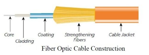
Submarine cables are made using fiber optic technology with taking into consideration environment and underwater factors. Accordingly, modern submarine cables are designed to resist various environmental circumstances. Figure below illustrates the content of modern submarine cable.
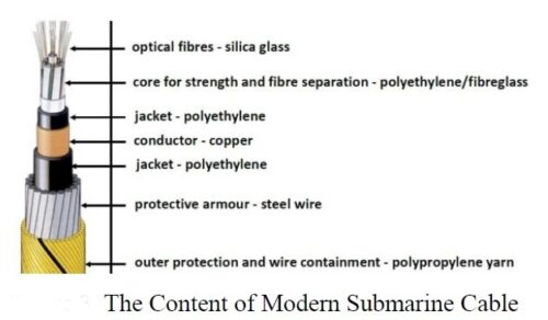
_
The main principle behind transporting signal in a type of light is based in refraction and reflection of that light. Then, interfacing between the two mediums is affecting any transporting of ray in a type of light that depends on the difference of speed of that light which travels in each material and that material has its own refraction. If this interfacing happened, one of three possibilities is going to happen, and this depends on the incidence angle and critical angle. So, if the incidence angle is less than the critical angle, the light ray will refract; and if they are equal, the light ray will continue traveling towards the surface of interfacing. The third possibility is if the incidence angle is greater than critical angle, the light ray will reflect. The latest possibility is desired to happen to complete propagate of data signals. The refraction index of core is 1.5 and claddings are 1.45 and together have a diameter range between 125 and 440 µm. Figure below illustrates the traveling of light in a fiber cable.
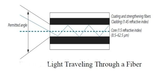
_
At their core, submarine fiber optic cables work the same way as fiber optic cables used on land. They transmit data through pulses of light traveling down thin glass strands called optical fibers. Each fiber is incredibly thin—just about as wide as a strand of human hair—but able to carry huge amounts of information at blazing speeds. How does this happen? The secret lies in a phenomenon called total internal reflection. Imagine shining a flashlight down a long, bendable pipe covered with mirrors inside. The light bounces around inside without escaping, traveling all the way to the other end. Optical fibers work similarly: they have a glass core surrounded by a “cladding” material. Because the core has a higher refractive index than the cladding, when light hits that boundary, it reflects inward, bouncing back and forth and staying inside the fiber.
But even lightspeed has limits—after traveling long distances underwater, the signal naturally weakens. To keep data clear and reliable across entire oceans, these cables use devices called repeaters. Placed about every 70 kilometers along a cable, repeaters amplify the weakening signals, boosting their strength so data stays crystal-clear. Modern repeaters use advanced technology called erbium-doped fiber amplifiers (EDFAs) to amplify signals directly as light, without converting them into electricity.
To squeeze even more data down these slim glass fibers, engineers use a clever technology called wavelength division multiplexing (WDM)—think of it as sending multiple streams of data, side-by-side, each riding a different color (or wavelength) of light. Dense WDM (DWDM) takes this idea further, packing dozens or even hundreds of data streams into a single fiber—dramatically boosting capacity.
_
Single vs multi-mode fibers:
There are two main types of fiber optic cable, the first is called single mode cable and the second is multimode cable. The core diameter of an optical fiber depends on whether it is single-mode or multi-mode. Single-mode fibers have a small core, typically 8 to 10 µ (most commonly 9 µ). Multi-mode fibers have larger cores, commonly 50 or 62.5 µ for telecommunications. Multimode fiber, as its name suggests, allows multiple light paths or modes to travel through the cable at once. It has a larger core, usually around 50 or 62.5 microns in diameter and this allows the use of less expensive light sources like LEDs. Although single-mode optical fiber holds advantages in terms of bandwidth and reach for longer distances, multimode optical fiber easily supports most distances required for enterprise and data center networks, at a cost significantly less than single-mode.
Because multiple modes/light paths travel down a multimode fiber cable, it only offers high bandwidth over a short distance. When run over longer distances, modal dispersion (distortion) becomes an issue. This is typically expressed in a fiber’s “effective modal bandwidth” characteristic, which is an inverse relation between fiber bandwidth and reach distance. As signaling bandwidth increases, the reach distance decreases – and vice versa – due to the modal dispersion effect.
In single mode fiber, all light from a pulse travel at about the same speed and arrives at roughly the same time, eliminating the effects of modal dispersion found in multimode fiber. This supports higher bandwidth levels with less signal loss over longer distances. It’s ideal for long-haul signal transmission applications, such as across or between campuses, undersea or in remote offices. There are essentially no distance limitations.
_
Why is Mono Mode fiber used for submarine cables?
Single mode fiber is pretty remarkable because it lets light go in one direction. This is distinct from the multi-mode fiber, which has multiple paths for light. The single path in mono mode fiber also results in less interference and less signal loss. Imagine attempting to speak with a distant friend. It becomes very easy to hear one another if you think about being in a quiet room. But if you’re in a loud environment, it is more difficult for the ear to hear. Mono mode fiber behaves much like the quiet room, as strong carrier signal is maintained. Even this strong a signal is super important for high-speed data transmission. It is this that has enabled people to send and receive information without delays. For instance, when you stream a movie, you want it to play quickly. Mono mode fiber does help that happen. It can also travel great distances with data, even thousands of miles under the ocean. That means cities and countries that are close now can still connect easily. One other cool fact about mono mode fiber is that it can handle a ton of data simultaneously. This is an important factor when there is heavy internet use. It’s a helpful way to keep things moving smoothly, whether you’re in a video call, playing online games or on your 48th virtual business meeting of the day.
______
______
DWDM:
Dense wavelength-division multiplexing (DWDM) is an optical transmission technology that uses multiple wavelengths of light to combine several data streams onto a single optical fiber. DWDM is a subset of wavelength-division multiplexing (WDM) that typically uses the spectrum band within 1530nm and 1625nm, or more commonly the C-band and L-band, to input 40, 88, 96 or even 160 wavelengths, or channels, onto a single strand of fiber optic cable. The International Telecommunication Union (ITU) has defined a normalized grid to allocate the system wavelength. Using this grid, up to 96 channels can be potentially used in the C-Band with a channel spacing of 50 GHz (about 0.4 nm).
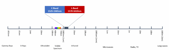
Figure above shows DWDM wavelength spectrum.
DWDM got its name from using tighter wavelength spacing (dense) to fit more channels, with each channel being only about 0.8nm wide. This is opposed to its WDM sibling, Coarse wavelength-division multiplexing (CWDM), where it uses a wider range of frequencies, with each channel spread farther apart. With a CWDM channel being 20nm wide, the high number of channels available to DWDM means it can cram much more data into the cable.
_
To explain how DWDM works, we first need to explain how the WDM works. Wavelength-division multiplexing, or WDM, uses a multiplexer to join several different data streams and convert them into wavelengths of light before transmitting it over the fiber optic cable, which is then de-multiplexed at its receiving end and split back into its respective streams of data.
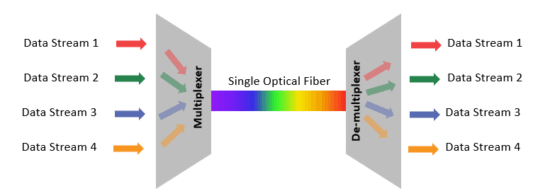
Figure above shows how DWDM works
Being a dense form of WDM, DWDM uses the same multiplexer to de-multiplexer transmission method, except that it can fit much more channels. To put that into perspective, if each channel carries 100Gbps of data, then at 160 channels per fiber cable, DWDM can essentially have a capacity of 16Tbps of data per fiber cable.
The major benefit of using DWDM technology is that it can transmit a large amount of data over a very long distance, which makes it very suitable for long-haul transmission. It can also be used with existing fiber optic cables with the means of increasing their data capacity as optical technology improves.
DWDM technology is useful when data needs to be sent across several states or even across oceans. Where it is much cheaper to install a DWDM system rather than laying down hundreds or thousands of kilometers of new fiber.
Another benefit DWDM technology has for data transmission is that DWDM is protocol and bitrate independent, because as data flows through each wavelength, the channels do not interfere with one another. This means DWDM can carry different types of traffic such as voice, video, and text over a single fiber optic cable, which is very beneficial to service providers who offer multiple services to their customers. This non-interference also helps to maintain the integrity of data and enable the separation of users and other types of partitioning applications.
_
DWDM networks utilize several properties of light in order to efficiently encode the information.
-1. Wavelength or frequency – each channel in a DWDM network uses a specific wavelength in the C-band, between approximately 1527 nm and 1565 nm. Each signal can provide varying bandwidth depending on the baud rate and modulation scheme.
-2. Phase – the angle of a waveform typically measured in radians. Changing the phase translates the period of the waveform in time.
-3. Amplitude – a measure of the total power of a signal in decibel-milliwatts (dBm).
-4. Polarization – electromagnetic waves have two primary polarization states defined by the electric and magnetic fields. Each polarization can contain information encoded by a modulation scheme. Some optical products use the notation Coherent Polarization-Multiplexed (CP) or Polarization Multiplexed (PM) in order to identify the use of polarization in the modulation.
_
DWDM Components:
The components of a traditional DWDM system consists of the transponder, multiplexer/de-multiplexer, optical add/drop multiplexers, and optical amplifiers, as depicted in the figure below.
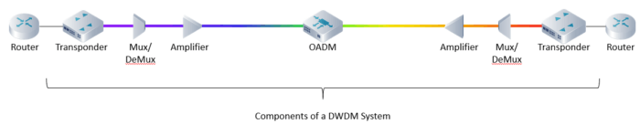
Below is overview of the process in which data is transmitted using DWDM and what each component’s function is within the system:
-1. The data stream comes in via the router and is input into the transponder.
-2. The transponder maps the signal to a DWDM wavelength and sends it to the multiplexer (Mux) to consolidate the optical signal.
-3. As the signal leaves the multiplexer, optical amplifiers boost the signal to allow the signal to travel over longer distances.
-4. Along the way, optical add/drop multiplexers (OADM) can add and remove bitstreams of a specific wavelength. Also, additional amplifiers can be used to further boost the signal’s distance.
-5. The signal the arrives and gets de-multiplexed (DeMux) into individual DWDM wavelengths, which are then passed through the transponder to be converted into the corresponding signals to be routed to its final destination.
______
______
Forward Error Correction:
All forms of telecommunications are affected by noise and are ultimately limited by the signal-to-noise ratio. Because of the constraints of the physical transmission medium, some transmitted information can be lost or modified.
Forward Error Correction (FEC) is a method of adding some bits to a transmitted digital transmission signal, and using those bits to correct errors in the received signal. The FEC process requires 3 basics steps:
- Encoding additional bits at transmit side,
- Decoding those bits at receive side,
- Using the decoded information to correct erroneous bits in the received signal.
Thanks to FEC techniques, strong improvements in Bit Error Rate (BER) performance are available and for instance, a BER of 4×10^-3 can be corrected into a BER of 10^-13 using the Bose, Chaudhuri and Hocquenghem code BCH(1020,988)x BCH(1020,988) which is already industrially implemented. This typically improves the terminal sensitivity by a net coding gain of 8.5dB for a BER of 10^-13. There are other benefits such as the use of forward error correction to improve the system margins, to improve the tolerance to polarization-dependent or non-linear effects and also to provide a quasi error-free operation for the system. Moreover the FEC allows the system operator to monitor the transmission quality. Due to equipment and fiber ageing, the bit error rate before FEC correction will increase whereas the BER after FEC will remain under the ITU limits. The fact that the number of FEC corrected errors can be monitored by software allows the operator to monitor the ageing of the system and keeps the overall system performance within the ITU limits.
Note:
In telecommunication transmission, the bit error rate (BER) is the percentage of bits that have errors relative to the total number of bits received in a transmission. For example, a transmission might have a BER of 10^-6, meaning that, out of 1,000,000 bits transmitted, one bit was in error.
______
______
Fiber pair:
In the realm of telecommunications and data transmission, the term “fiber pair” refers to a pair of optical fibers used in fiber optic communication systems. These fibers are designed to carry data over long distances with minimal loss of signal quality, making them a crucial component in modern communication infrastructure, including the internet, cable television, and telephone systems.
A fiber pair consists of two optical fiber strands, with one dedicated to transmitting (TX) data and the other to receiving (RX) data, enabling simultaneous bi-directional communication. Commonly used in data centers and long-haul networks, this configuration ensures high-speed, high-bandwidth data transmission with low signal loss.
_
Fiber optic technology uses light to transmit data rather than electrical signals. This method offers numerous advantages, such as higher bandwidth, longer transmission distances without the need for signal boosters, and immunity to electromagnetic interference, making it ideal for high-speed data transmission.
A fiber pair consists of two individual fibers within a fiber optic cable. Each fiber in the pair serves a specific function in the data transmission process:
-1. Transmit Fiber: One fiber is designated for transmitting data signals. It carries light pulses generated by a laser or LED at the transmitting end.
-2. Receive Fiber: The other fiber is used for receiving data signals. It captures light pulses sent from the transmitting end of another device or network.
This bidirectional communication capability allows for simultaneous two-way data transmission, which is essential for efficient communication networks.
_
Advantages of using Fiber Pairs:
The use of fiber pairs in communication systems offers several advantages:
-1. High Bandwidth: Fiber optic cables can carry a vast amount of data, making them ideal for high-speed internet and data-intensive applications.
-2. Long Distance Transmission: Fiber pairs can transmit data over long distances without significant signal loss, reducing the need for repeaters and amplifiers.
-3. Immunity to Electromagnetic Interference: Unlike copper cables, fiber optic cables are not affected by electromagnetic interference, ensuring a stable and reliable connection.
-4. Security: Fiber optic cables are difficult to tap into without detection, making them a secure option for transmitting sensitive data.
-5. Scalability: As data demands increase, fiber optic networks can be easily upgraded to accommodate higher bandwidths.
______
______
How to increase capacity of submarine cables by Technological Innovations:
The transmission capacity of the first SMF-based system launched in the 1980s was a few tens of Mb/s. In contrast, the latest terrestrial and submarine systems now support more than 10 Tb/s per SMF with a spectral efficiency of more than 2 b/s/Hz. The capacity growth rate over the past 40 years corresponds to 40% per year. This suggests that optical transmission systems will be able to support more than 100Tb/s capacity in 2025 and over 1-Pb/s capacity by the early 2030s. However, the existing G.65x fibres have a limited maximum capacity because the maximum input power in an SMF is limited by an optical nonlinear effect, which results in limited improvement in the optical signal-to-noise ratio (OSNR). The total input power of all the DWDM channels is also restricted by a physical limitation, namely the fibre fuse. Thus, the maximum capacity in one SMF is limited to around 110 Tb/s when an optically amplified transmission window and a spectral efficiency are assumed to be a C-L band and 10-b/s/Hz, respectively. Even if the S-L band is available as an optically amplified DWDM transmission bandwidth, the maximum capacity of one SMF will be difficult to increase beyond 200 Tb/s.
_
Scaling optical fiber capacities has been the focus of multiple generations of Digital Signal Processors (DSP) and high-speed optical components over the last decade. However, as we approached Shannon Capacity limits, capacity gains from coherent transponder innovation alone are getting incrementally smaller and a new approach was needed. Accessing additional spectrum and packing more fibers into the cable was the next step to continue raising fiber capacities while observing available electrical power constraints.
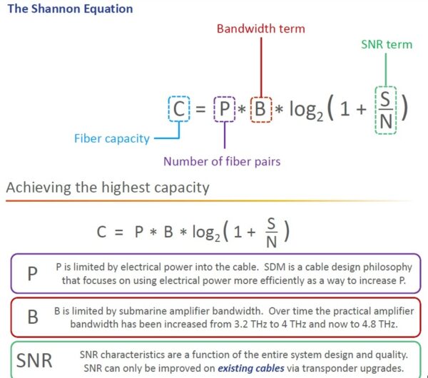
_
A new generation of undersea cables was developed to use higher count of fiber pairs. At slightly reduced capacity of each fiber pair, the total cable capacity is increased drastically by taking advantage of the linear bandwidth gain from additional fiber pairs and trade off the logarithmic scale repeater power gain per fiber pair (i.e., OSNR). Space Division Multiplexing, or SDM, is the term used to describe these new cables. SDM increases the cable fiber pair count from 4-8 pairs to 12, 16 and upward of more than 20 fiber pairs. In its most conventional sense, SDM could simply mean more fibres in the cable. However, to further increase cable capacity by means of a further increase in spatial paths, the belief within the industry is that more radical solutions will be needed. Such solutions may involve reduced-coating diameter fibres (RCDF), reduced-cladding fibres (RCF), a multicore fibre (MCF), or few-mode fibre (FMF).
_
-1. SDM cables:
There are different ways to meet the high traffic demand in Submarine cable. We need more capacity. Demands keep on increasing. How we can achieve it?
More Submarine cables, more number of channels (C+L band system), more number of fiber pairs, increasing per fiber capacity, increasing channel bandwidth i.e. transponder/modem capacity.
Before 2018, the focus was on increasing the per fiber pair capacity. However, it has almost reached the maximum. Then why not, increasing the capacity in system level. Increasing the capacity of submarine cable by adding more fiber pairs is called SDM.
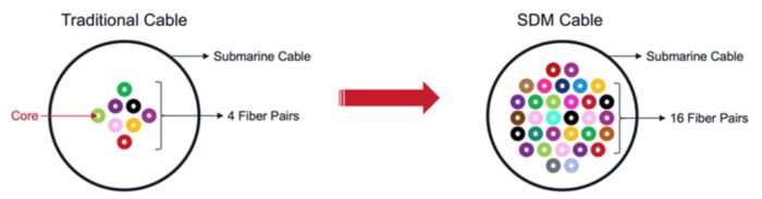
Figure above shows Traditional vs. Spatial Division Multiplexing (SDM) submarine cables.
Spatial Division Multiplexing (SDM) is a new submarine cable paradigm that allows for higher total cable capacity by increasing the number of fiber pairs in a cable, even if capacity per pair is lower. SDM cables sacrifice spectral efficiency per pair in order to add more pairs and compensate with a higher cable capacity overall. This approach helps maximize capacity as we near the limits imposed by Shannon’s law. Initial SDM cables deployed around 12-24 fiber pairs and achieved cable capacities over 300Tbps.
In the past, everyone’s goal was to maximize the amount of bandwidth per fiber pair, more wavelengths, and a higher bit rate per wavelength. Now the trend has been shifted to an emphasis on more fiber pairs in a single cable. These new cables being planned with so-called SDM. A key advantage of SDM is its ability to allow multiple fiber pairs to share pump lasers and other optical components. This contrasts with traditional subsea cables, where each fiber pair requires its own dedicated set of pump lasers. Implementing SDM is not only technologically advanced but also cost-effective. It enhances the cable’s capacity without significantly increasing costs.
Traditional cable has 4 to 8 fiber pairs. The maximum what we know in traditional subsea cable is 8 fiber pairs. While SDM cable will have 12 to 16 fiber pairs and potentially more in future. More fiber pairs, more cable capacity. Greater capacity can be realized through spatial division Multiplexing (SDM) in which more fiber pairs carry channels with lower power and signal-to noise ratio (SNR).
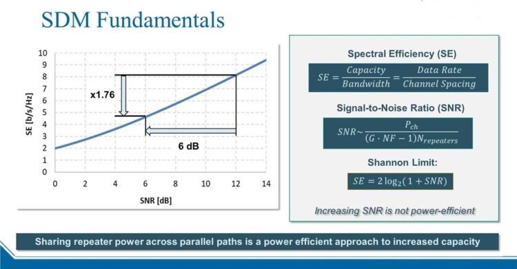
- Traditional Cable Example: 6 fibre pairs X 20Tbps each = 120Tbps Total Capacity
- SDM Submarine Cable Example: 16 Fibre pairs X 16Tbps each = 256Tbps total capacity
First SDM submarine cable will be Google’s transatlantic 6,400km Dunant cable, which supports up to 250Tb/s of overall capacity provided by an aggregate of 12 fiber pairs.
_
-2. Multi-core cables:
Although SDM is the new way to massively increase the information-carrying capacity of submarine cables, other wet plant innovations are being considered to further increase capacities. One such innovation is Multi-Core Fiber (MCF) cables, shown in Figure below, which add two or more optical cores, which theoretically doubles the capacity of the fiber. In lab tests, these multi-core fibers have already smashed records, reaching incredibly low losses of just 0.155 dB/km. Basically, this allows cables to handle far more data over longer distances without signal degradation. If cores are far enough apart, say with 2 cores, MCF is “uncoupled”, while cores close together are “coupled”. The latter means optical transmission in adjacent cores will interact and interfere with each other thus requiring new techniques, such as Massive Input Massive Output (MIMO) used in wireless network transmission. A new generation of coherent modems that exploit coupled MCF submarine cables will subsequently require a significant amount of time, investment, and development.
_
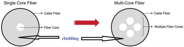
Figure above shows Single-Core Fiber vs. Multi-Core Fiber (4 cores shown).
Multi-core fiber (MCF) has multiple cores in its cladding glass as schematically shown in figure above. It is highly expected to increase the transmission capacity of submarine cable.
KDDI Research, Tohoku University, Sumitomo Electric, Furukawa Electric, NEC, and Optoquest were commissioned to conduct research and development of multicore fibers that house multiple light propagating cores in an optical fiber, which helps to overcome the limitations of conventional optical fibers. The six organizations have developed and demonstrated the fundamental technologies needed to realize a sustainable, high-capacity submarine optical cable system. Combining all development and verification results, the feasibility of expanding transmission capacity to approx. 1.74 Pbit/s has been verified for a 3,000 km-class optical submarine cable system covering the Asia-Pacific region by using submarine optical cables containing 32 fibers (16 pairs) of four-core fibers, multifunctional devices, and optical amplification repeaters.
_
-3. More bands:
There’s also the possibility of leveraging C+L Band submarine cables, which has since been sidelined with the advent of C-band SDM cables, in the future. Leveraging L-Band gets more fiber capacity using more spectrum within the fiber-optic core and requires L-band capable SLTE modems and an L-band capable wet plant.
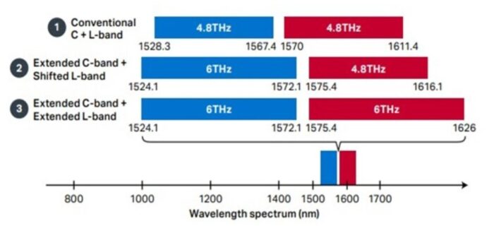
Figure above shows options for increasing optical fiber capacity with L-band
By leveraging the latest SLTE modems alongside SDM, MCF, and C+L Band wet plants, we should be able to achieve submarine cables with total capacities in the multiple petabits per second (Pb/s), where 1Pb/s is 1,000,000,000,000,000 bits per second.
_
-4. Open Cables:
Open Cables is a concept in submarine telecommunications where the cable system is designed for compatibility with multiple types of networking equipment, rather than being tied to a specific vendor. This approach fundamentally separates the ‘wet plant’ components (which include the cable, repeaters, and branching units) from the ‘dry plant’ elements (namely the optical transmission equipment).
At each end of a cable is a cable landing station; much like a ‘normal’ data center, it houses important networking equipment which powers the cable and controls its operations. Traditionally, submarine line terminal equipment (SLTE) and power feed equipment (PFE) of a submarine cable system were installed at the cable landing station. The Open Cables model resulted in numerous new upgrade vendors joining the submarine networking industry, and submarine cable operators have understood and appreciated the benefit of a broader choice of SLTE technology and vendors. Submarine systems, such as Southern Cross, are now capable of more than 80 times their original design capacity with upgrades to SLTE technology.
Adopting the Open Cables strategy provides significant advantages. It offers greater flexibility and choice for cable system owners and operators, particularly in selecting transmission equipment vendors. This can lead to cost savings and facilitate easier system upgrades. Furthermore, this approach fosters innovation by allowing the integration of diverse and emerging technologies, as they become available.
_
-5. Unconventional wisdom:
The transponders used in submarine networks are usually based on the same optical engines as terrestrial transponders, but often use specially selected optical and electronic components in order to minimize noise in the circuit. But the best submarine transponders will go a step further and include features that help to optimize performance in all types of submarine cables. Modern transponders are highly programmable, and in terrestrial networks, conventional wisdom dictates:
- Always use the highest baud rate of the transponder
- Always use probabilistic constellation shaping (PCS)…to deliver maximum optical performance.
The reason this wisdom holds true for terrestrial networks is that we are dealing with large numbers of wavelength services over diversely routed optical paths, usually in a meshed topology. In other words, the design philosophy is to keep things simple while achieving the highest practical performance.
In submarine networks, fiber capacity is incredibly valuable, while topology is relatively simple, so it becomes worthwhile to spend time optimizing the fiber channel plan and configuring different parts of the spectrum in different ways to achieve maximum performance. Moreover, a high-quality subsea transponder solution will include a degree of automation for this design process.
Conventional wisdom gained from terrestrial network deployments does not always transfer well to submarine cables, no matter what type of cable. The use of variable high-baud-rate transponders and non-PCS modulation types can help fiber pair operators enhance performance dramatically in all submarine cable types.
_______
The capacity challenge:
Typically, the higher the capacity per fiber pair of an undersea communication system the lower the cost per transported bit since the total system cost can be amortized over a larger capacity. This simple fact explains the drive towards higher and higher capacity in submarine systems. Figure below summarizes the experimentally demonstrated transmission capacity over transoceanic distances (>6000 km) since 2000, when the first >1 Tb/s transoceanic transmission was demonstrated.
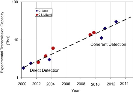
Figure above shows Experimentally demonstrated single-fiber transoceanic capacity records.
_
Since fiber pair capacity is simply the product of the repeater bandwidth (BW) and the spectral efficiency of the transmitted signals, fiber pair capacity can be increased in two ways. One, by increasing the repeater bandwidth and two, by increasing the spectral efficiency of the transmitted signals. Much effort has been devoted to maximizing both of these parameters. Repeater bandwidths up to 80 nm have been demonstrated as early as 2002 but so far commercial applications in the undersea space are limited to the full C-band of about 40 nm or 5 THz for various reasons. Coherent techniques on the other hand have enabled dramatic progress in spectral efficiency over the last few years.
_
Progress in ASIC (application specific integrated circuit) technology enables powerful digital signal processing (DSP) which makes coherent transmission technology practical for commercial applications. Coherent transmission and DSP provide much of the advancement in undersea transmission technology over the past few years allowing for higher spectral efficiency and capacity. Spectral efficiency (SE) describes how well bandwidth is utilized in terms of transmitted information. In optical communication systems it can be expressed by the ratio of the channel information rate (RI) and the channel spacing Δf (see Figure below).
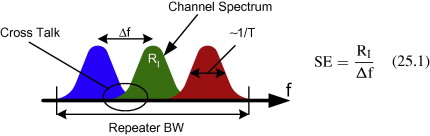
Figure above shows that Spectral efficiency is the ratio of information rate RI to channel spacing Δf. Cross talk limits the achievable spectral efficiency.
For example, in a direct detection system just a few years ago the channel information rate was 10 Gb/s and the channel spacing 25 GHz for a spectral efficiency of 0.4 b/s/Hz. To increase spectral efficiency the information rate per channel must be increased and/or the channel spacing decreased. However, the spectral width of a channel is proportional to the inverse symbol pulse width 1/T which is related to the symbol rate. Once the channel spectra start to overlap, there will be channel crosstalk and transmission performance rapidly decreases which limits the spectral efficiency that can be achieved.
_
Coherent detection can help us in several ways to further increase spectral efficiency. First, single mode fiber actually supports two degenerate orthogonal polarization modes that can be separated effectively with coherent detection and used nearly independently by polarization multiplexing doubling the information rate of a channel without changing its spectral width. Second, coherent transmission also allows us to depart from binary transmission formats and transmit more than one bit per symbol without incurring fundamental implementation penalties. Since the spectral width of a channel is determined by the symbol rate not the bit rate, its spectral width is unchanged and we can increase the information rate for the same channel spacing. These two steps, polarization multiplexing and demultiplexing as well as quadrature phase shift keying (QPSK) with 2 bits per symbol alone allow us to increase spectral efficiency fourfold compared with a single polarization binary format.
_
In the last few years even higher spectral efficiencies have been achieved enabled by coherent techniques. One approach is bandwidth constraint by strong optical filtering. The spectral width of a channel can be reduced significantly by optical filtering which then enables smaller channel spacing values and therefore higher spectral efficiency. However, when reducing the spectral width of a channel by filtering, the signal pulses in the time domain broaden and pulses start to overlap causing inter-symbol interference (ISI) rapidly decreasing transmission performance. Coherent detection allows us to process the received optical field and introduce advanced filters and algorithms that can correct ISI and mitigate the penalty associated with strong optical filtering. Another approach to increasing spectral efficiency is to go to higher order modulation formats with combinations of amplitude and phase modulation and more bits per symbol increasing the information rate and/or decreasing the spectral width per channel. Coherent detection makes these formats practical. However, receiver sensitivity decreases with higher order modulation formats requiring a higher optical signal-to-noise ratio (OSNR) and limiting the transmission distance and spectral efficiency that can be achieved.
_
Dense Wavelength Division Multiplexing (DWDM) and coherent technology form a formidable partnership in the domain of long-haul data transmission. The synergy between these two innovations boosts the capabilities of modern communication networks. DWDM combines multiple wavelengths of light onto a single optical fiber, which magnifies the capacity exponentially. Complementing this, coherent technology further enhances signal quality and efficiency by utilizing advanced modulation formats, adept digital signal processing, and intricate error correction techniques. DWDM and coherent technology enable signal transmission speeds of up to 800 Gb/s per wavelength, especially for ultra-long-haul and uncompensated submarine applications. Based on technology, DWDM / ROADM systems can typically support a range of 40 to 96 channels or wavelengths per fiber cable.
______
______
Evolution of Submarine Cables Technology:
Undersea communication systems have been providing low latency and high-capacity connectivity between the continents of the world for more than 150 years. The first transoceanic telegraph cable became operational in 1858 with a communication speed of about 2 min per character, a vast improvement over the 10 days it took to deliver a message by clipper ship. The cable spanned a 4025 km route between Newfoundland and Ireland and lasted only for about a month but was successfully replaced in 1866 with an increased transmission speed of about 8 words per minute.
_
Steady progress has been made ever since to provide faster and faster communication speed or higher and higher bandwidth with submarine cables. Voice traffic on a transatlantic cable became available in 1956 with Transatlantic No. 1 (TAT-1) carrying 36 simultaneous telephone channels with 4 kHz bandwidth each replacing radio connections that had been in use between the United States and Europe since 1927 but which were unreliable due to their dependence on atmospheric conditions. In 1988 the first fiber optic transatlantic cable was put into service ultimately carrying 40,000 telephone circuits equivalent to 560 Mb/s of aggregate traffic on two fiber pairs. The latest generation of systems in the Atlantic between the United States and Europe can carry multiple Tb/s of aggregate capacity and the next generation is actively being discussed with multiple tens of Tb/s capacity.
_
Typical transatlantic type systems have a length of about 6,000 km or more. Distances in the Pacific are even longer. A typical connection between the United States and Japan is about 9,000 km and between the United States and South East Asia can be up to 11,000 km or more. This is much longer than any terrestrial system. However, there is also some advantage compared with terrestrial systems. A submarine system owner does not have to install a new system onto an existing fiber route as is common for terrestrial systems but can freely design the transmission path and choose fiber types and amplifier spacing for the best solution of a new system. Undersea amplifiers are often called “repeaters” and are based on Erbium doped fiber amplifiers (EDFA) that amplify the optical signals without any retiming or reshaping.
_
Many people believe that their international internet data and telephone connections are carried by satellites. For a great many connections, however, that is not true. Most intercontinental traffic is carried by undersea cables. Compared with satellite connections undersea cables have a significant advantage. The signals travel along a much more direct and therefore shorter path. A geostationary satellite orbits earth at about 36,000 km above the equator such that a roundtrip signal between two points on the globe would travel at least 4 times that distance or 144,000 km. At the speed of light it takes 0.48 s to travel this distance, a significant delay that is noticeable and irritating in a telephone conversation. Low latency is even more important in modern applications. Round trip latencies as low as sub-60 ms have been announced between New York and London, a significant achievement considering that the great circle distance is about 5600 km and therefore the minimum latency between New York and London is 54 ms using a refractive index of 1.45 for optical fiber.
_
Undersea systems have another advantage: massive capacity. A modern cable can carry about 100 channels at 100 Gb/s each per fiber depending on distance. Since a cable can typically contain up to 8 fiber pairs (one fiber for each direction in a pair) this equates to 80 Tb/s in each direction. Satellite communication links use microwave radio for transmission and are typically limited to several Gb/s capacity.
_
Optical networks are seeking for extra bandwidth from the time they were born. The reason for that lies to vast number of users in both internet and private networks and, of course, to bandwidth hungry applications. Space Division Multiplexing (SDM) aims to meet future needs. SDM transmission technology utilizes the extra fiber pairs by performing the transmission across spatially diverse pathways (multiple fibers in this case). Therefore, as part of the SDM design, pump lasers and related optical components are shared among multiple fiber pairs as opposed to being dedicated supporting only a single fiber pair.
Figure below shows the evolution of submarine cable systems achieved bandwidth through time.
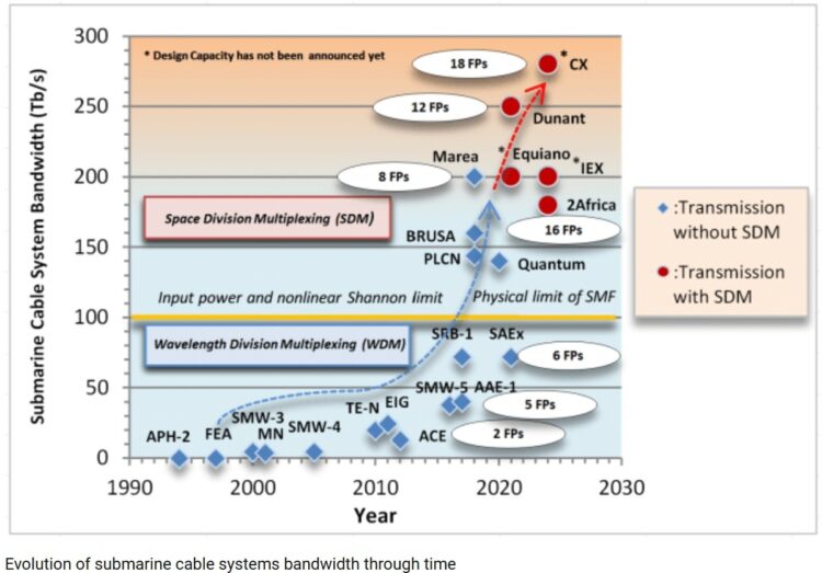
One of the latest advancements in submerged repeater technology is the Repeater Pump Farming which aims to provide maximum redundancy and flexibility. The Repeater Pump farming is, as its name suggests, a farm (a group) of repeaters cross connected to each other, supporting the same group of fiber pairs. So, we have a pool of pumps to support a pool of Fiber Pairs. This serves the obvious: redundancy, and consequently, reliability, even in the case of multiple repeater failures.
______
Global data traffic has been growing by 30 to 40% per year in line with the spread of 5G mobile communication, expansion of cloud services, and construction of data centers in respective countries (see Figure below, top). To meet this growing demand, there is a strong requirement to expand the transmission capacity through a submarine cable. In fact, submarine cable transmission capacity has been increasing in line with the advancement of optical transmission technology and optical fiber (see Figure below, bottom).
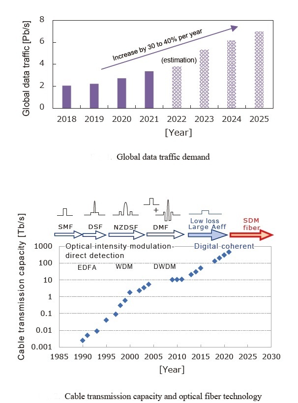
Before the 1990s, a single-wavelength transmission over standard single-mode fiber (SMF) was used. Then, wavelength division multiplexing technologies (WDM, DWDM) using optical fiber amplifier (EDFA) were introduced and chromatic dispersion became the main constraint for transmission capacity, and therefore, dispersion-shifted fiber (DSF), non-zero dispersion-shifted fiber (NZDSF) and dispersion- managed fiber (DMF) were adopted.
In the 2010s, the optical signal to-noise ratio (OSNR) emerged as the main constraint factor by the introduction of digital coherent technology. To improve OSNR, it is important to reduce fiber nonlinearity and transmission loss. Therefore, an optical fiber having low nonlinearity by enlarging effective area (Aeff) to 130 to 150 μm2, and ultra-low loss (0.15 dB/km) by applying pure silica core technology was optimal. This fiber represents very high performance compared with standard SMF (Aeff: 80 μm2, transmission loss: 0.18 to 0.20 dB/km).
In around 2020, transmission capacity per optical fiber almost reached the theoretical limit. Thus, space division multiplexing (SDM) technology was introduced to increase transmission capacity by increasing the number of fibers in a cable. Today, optical fibers with Aeff of 80 to 130 μm2 and ultra-low loss of 0.15 dB/km are utilized mainly.
______
SMART cables:
Environmental engineers are calling for future subsea cables to be fitted with dedicated sensors to measure pressure, temperature and acceleration. This will provide a more comprehensive monitoring system for early detection of seismic events, as well as for climate and ocean observation. The sensing technologies needed for such Science Monitoring And Reliable Telecommunications (SMART) cables have already been demonstrated in underwater geophysical observatories, notably two large-scale networks in Japan that were deployed in the wake of the 2011 Tōhoku earthquake and tsunami. However, more work is needed to demonstrate a practical SMART cable that meets the needs of commercial telecoms operators as well as environmental scientists.
_______
_______
Fiber-in, Copper-out:
The transition from copper to fiber optic cabling, often referred to as “fiber-in, copper-out,” has significantly impacted network infrastructure by enhancing bandwidth, improving reliability, and driving technological advancements. This shift is a global trend, with various countries and service providers actively replacing older copper networks to meet increasing demands for faster and more stable internet services.
- Increased Bandwidth and Speed: Fiber optic cables offer substantially greater data transmission capacity and speed compared to traditional copper wiring, which is crucial for supporting modern applications like cloud services, IoT, and high-quality video streaming.
- Enhanced Reliability and Longevity: Fiber systems are generally more durable and have a longer lifespan than copper cabling, reducing the frequency of replacements and maintenance. This also contributes to energy saving efficiencies.
- Support for Advanced Technologies: The move to fiber infrastructure is essential for enabling new technologies such as Wi-Fi 6, 5G, and advanced telemedicine, which require high-quality, low-latency connectivity.
The ongoing global shift from copper to fiber optic infrastructure is a response to the escalating demand for high-speed, reliable connectivity. This transition, while presenting logistical and financial challenges, is fundamental to supporting current and future technological advancements and ensuring robust network performance.
__
Undersea internet cables, which carry over 95% of international data, now feature incredible speeds, with modern systems transmitting over 200 terabits per second (Tbps) and total cable system capacities reaching into the hundreds of Tbps. These fiber-optic cables use light to send data, enabling transoceanic speeds at least five times faster than satellites.
Key Data Speed and Capacity Details:
- Total Capacity: Newest systems often boast capacities exceeding 200 Tbps
- Per Fiber Pair: Modern, high-capacity routes can deliver around 10-20 Tbps per fiber pair, utilizing multiple wavelengths.
- Performance: These cables provide exceptionally low latency, with, for example, transoceanic pings often below 250 ms.
Factors Influencing Speed:
- Light Transmission: Fiber-optic technology allows for high-frequency, long-distance data transmission, which is much faster than copper.
- Fiber Pairs: The total capacity depends heavily on the number of fiber pairs within the cable, which can range from a few to dozens.
- Equipment Upgrades: The speed is often limited by the terminating equipment (repeaters, transceivers) rather than the cable itself, allowing for capacity upgrades over time.
These undersea, fiber-optic pathways act as the “unseen backbone” of the global internet, with capacities far exceeding any satellite-based technology.
______
______
Technical Limitations of Physical Infrastructure of submarine fiber optic cables:
Understanding the technical limitations of physical infrastructure is critical for businesses dependent on digital connectivity. The internet isn’t a magical, non-material entity – it’s bound by physical laws and constraints that directly impact performance:
Light Speed Limitations: Data travels through fiber optic cables at approximately two-thirds the speed of light. This creates a minimum theoretical latency between locations that simply cannot be overcome. For example, the minimum round-trip time between New York and London is around 60ms, purely due to distance. No technology can beat this physical limitation.
Cable Capacity Bottlenecks: Modern submarine cables use Dense Wavelength Division Multiplexing (DWDM) technology to transmit multiple light wavelengths through a single fiber, with each wavelength carrying up to 100-400Gbps. However, even with these impressive specifications, total capacity is finite and must be shared among all connected users and services.
Peering Points and Routing Inefficiencies: Data doesn’t always take the most direct route. Traffic often travels through multiple exchange points and peering arrangements, each adding microseconds or milliseconds to transmission time. The physical location of these peering points significantly impacts overall network performance.
Cable Diversity and Redundancy: The physical path your data takes matters immensely for reliability. Businesses with mission-critical applications need connectivity through diverse cable systems with different landing points and undersea routes to ensure continuity when individual cables experience issues.
Signal Regeneration Requirements: Over long distances, optical signals degrade and require regeneration approximately every 70-100km. Each regeneration point introduces minute delays and potential points of failure in the physical infrastructure.
______
______
Section-5
Anatomy of subsea optical fiber cable:
The basic physical cable design that’s used today for these subsea systems is much the same as the early designs. The signal bearer itself has changed from copper to fibre, but the remainder of the cable is much the same. A steel strength member is included with the signal bearers and these signal cables are wrapped in a gel to prevent abrasion. In our hyper-connected world, fiber optic cables serve as the invisible backbone of modern communication. While standard fiber optic cables dominate land-based networks—serving data centers, homes, and enterprise infrastructure—submarine fiber optic cables (also known as undersea or subsea cables) quietly handle the lion’s share of global internet traffic. Though both technologies use the same core principles—transmitting data as pulses of light—their designs, materials, and deployment methods differ significantly. Both use DWDM technology, but submarine cables require ultra-pure glass, precision lasers, and low-noise amplification for global performance.
_
A Fibre Optic Cable consists of an inner optical core encased within a high tensile steel strength member, covered within a copper power conductor. This package is then insulated with polyethylene. This package is the basic deep-water cable (water depths greater than 2,000 metres) and is usually 17 – 21mm diameter and they weigh 1.4 tons per kilometre. The combined length of the cables is estimated to be more than 1.5 million of kilometres. If all cables were put in sequence one after another, they would go around the globe 35 times.
_
The optical (light) signal is carried on pure glass fibre cased within the optical core. The light is guided by internal reflection within the glass fibre. Each fibre, of which there may be many, is much smaller in diameter than a human hair. Because the light signal loses strength enroute, repeaters are required at regular intervals to restore it. Repeaters are now based on optical amplifying technology, which requires short lengths of erbium-doped optical fibre to be spliced into the cable system. These are then energized by lasers, thus boosting the incoming light signal. Repeaters need to be spaced every 50 to 80 kilometres apart and since each repeater requires electrical power to operate it, long length submarine cables are powered and the voltages carried may be very high. Damage to, or loss of a repeater can result in a very expensive repair or replacement, as well as breakdown in commercial business communications. Shorter submarine cables, such as those across the Irish Sea or English Channel, do not need repeaters and have amplifiers at either end. It is possible to have a single span of around 240km without the need for a repeater.
_
Cable systems may also have devices called Branching Units inserted into them. The Branching Unit looks like a ‘Y’ shaped cable connector and are very large. The branching unit can be used to spilt the cable path to enable the cable to be routed to two or more different locations thus allowing diversity of connection for the cable system. More than one Branching Unit can be used in a cable system and indeed, many cable systems use multiple Branching Units to allow multiple connections.
_
In water less than 2,000 meters deep, additional protection is added against environmental, fishing and anchor damage in the form of external steel wire armour clad within a polypropylene serving. There may be one or more layers of armour applied to the cable. The heaviest form of armoured cable may have in excess of 70 tonnes breaking strength. While the cable may only break or part at high tensions, damage to the optical path or to the electrical insulation (the polyethylene) can occur at much lower tensions such as when fishing gear may become engaged with the cable. This is because the cable becomes bent to a radius less than its minimum safe limits (usually 1.5 metres radius/3 metre diameter). Armoured cables vary in size depending on whether one or more armour layers are used but may be up to 50mm diameter. Breaking strains vary from 20 – 70 or more tonnes.
_
Submarine cable is buried typically 0.5-3m depth in shallower waters under 1,500m, or surface-laid beyond 2,000m. The actual thickness depends on the section and protection. In open sea, diameters can vary in the range of 25 to 50 mm, while there are commercial families with variants from 17 to 41 millimeters for certain areas. Near the coast, where there are anchors and fishing, the armour grows and there are cables that exceed the 20 centimeters in diameter, reaching a weight of between 40 and 70 kg per meter in the most reinforced sections. The designed useful life is around 25 years, after which the system is usually removed or replaced. Along its route, the cable is divided into large segments and may include optical repeaters at regular intervals; these parts also determine how to plan an arrangement whether they need to be recovered or replaced.
_______
An annotated graphic showing the materials that make up an undersea cable:
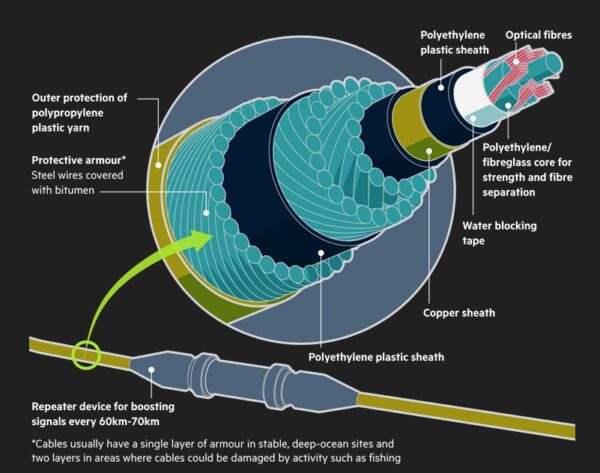
_
Glass Cores:
The core of an optical fiber is a thin strand of glass or plastic, typically about the diameter of a human hair. This core is where light travels. Single-mode fibers have a very narrow core (around 9 microns in diameter), allowing light to travel straight down the fiber, making them ideal for long-distance communication. Multi-mode fibers, on the other hand, have a broader core (50 or 62.5 microns), allowing multiple light paths or modes. This makes them suitable for shorter distances.
Cladding:
Surrounding the core is the cladding, a layer of glass or plastic with a different refractive index. The cladding’s job is to keep the light signals within the core through a process called total internal reflection. This ensures that the light signals can travel long distances without escaping the core, maintaining the integrity and speed of data transmission.
Protective Jacket:
The outermost layer of a fiber optic cable is the protective jacket. This jacket is made from durable materials like plastic to shield the delicate glass fibers from physical damage, moisture, and other environmental factors. Depending on the intended use, the protective jacket can vary in thickness and strength.
_
Since the late 1980s, commercial undersea telecommunication cable owners have used optical fibers—thin, flexible, and highly transparent glass or plastic strands—to facilitate long-distance communications. Optical fibers allow signals to be sent over long distances using light pulses instead of electricity, which, when compared with traditional copper lines, results in a clearer signal, less signal loss over long distances, greater bandwidth, and less electromagnetic interference. Due to these advantages, network architects assert that optical fiber is the best physical medium to facilitate long distance communication and connect global networks. Optical fibers carry communications (e.g., voice, video and data) in the form of colored light signals of various wavelengths (using a technique known as wavelength division multiplexing) to enable high-speed, long-distance communications. The optical fibers themselves are encased in successive layers of materials to transmit power, and to strengthen and insulate the cable. Figure below illustrates the bundled materials in a typical undersea fiber-optic cable. Undersea Fiber-Optic Cable Cross-Section is depicted in figure below:
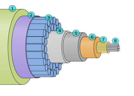
(1) Polyethylene, (2) Mylar tape, (3) Stranded metal (steel) wires, (4) Aluminum water barrier, (5) Polycarbonate, (6) Copper or aluminum tube, (7) Petroleum jelly, and (8) Optical fibers.
Multiple fiber optic cores can be combined within the outer insulation and strengthening layers of an undersea telecommunication cable. Near to the shore, the cable is wrapped in tough shielding to protect against danger and damage from activities occurring near to shore (e.g., fishing, shipping, and other marine activities). Undersea cables can carry multiple fiber pairs, enabling numerous providers to use the same cable. Most cables transmit in one direction on one fiber in a pair and in the reverse direction on the other. As optical signals pass from one segment of an undersea telecommunication cable to the next, repeaters boost the signal with optical amplifiers using semiconductor laser pumps, allowing the signal to travel long distances, and controlling the signal with optical equalizers to maintain its integrity.
_
The core of the submarine optical cable uses a hair-like high-purity optical fiber to guide light along the optical fiber path through internal reflection. The submarine optical cable must be able to withstand the huge pressure of 8 kilometers underwater, which is equivalent to the weight of an elephant on a human thumb. In the production of submarine optical cables, optical fibers are first embedded in a jelly-like compound to protect the optical cable from damage even when it comes in contact with seawater. Then put the optical cable into the steel pipe to prevent water pressure damage. It is then wrapped with steel wire with extremely high comprehensive strength, then wrapped with a copper pipe, and finally covered with a protective layer of polyethylene material. Near the coast of the continental shelf, submarine cables are usually laid with light cables, using stronger steel wires, and covered with asphalt coatings to prevent seawater corrosion.
_
From the outside, a submarine fiber optic cable looks simple—just about as thick as your garden hose. But cut it open, and you’ll find a marvel of modern engineering specifically designed for the rough conditions deep beneath the ocean surface. At the very center of the cable are those precious optical fibers themselves. Made from ultra-pure silica glass, modern submarine cables typically have anywhere from 2 to 24 fiber pairs. They often use a special type called G.654 fiber, designed specifically for long underwater journeys. These fibers experience very low signal loss (attenuation)—usually between 0.15 and 0.17 dB/km—far better than standard fibers used on land. Surrounding these delicate glass fibers is a stainless steel tube filled with protective gel. This combination provides initial protection from crushing deep-sea pressures and prevents water damage that could disrupt the signals.
Adding to the cable’s strength and durability are multiple protective layers:
- Steel strength members: Wires that provide the necessary strength for installation and recovery from the seabed.
- Copper conductor: Often included to deliver electrical power to the repeaters along the route.
- Water-blocking materials: Special layers that keep water from seeping into the cable if the outer layers get damaged.
- Polyethylene sheath: A tough, insulating plastic covering that offers additional protection.
- Steel armor: Extra protection for cables placed in shallow waters, where they’re more vulnerable to fishing gear, anchors, and other hazards.
Cables designed for deeper ocean sections are generally thinner and lighter, while those closer to shore get more steel armor for extra protection. There’s a fascinating balance between strength, flexibility, and protection in every submarine fiber optic cable. The cable’s physical design—from a thin core of optical fibers to multiple protective layers and external armor—ensures both functionality and resilience in harsh underwater environments.
__
Different cables are used for submarine applications, but generally follow the basic scheme as seen in figure below:
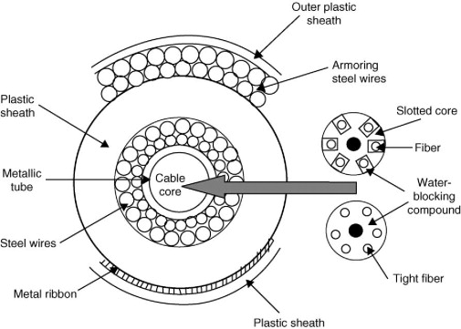
Figure above shows basic structure of a submarine cable.
The central core (with a few fibers – up to 12 – in a slotted core or in a tight structure) is surrounded by a double layer of steel wires that act as strength members against tensile action and water pressure. Metal pipes at the inner or outer sides of the strength member, act as a water barrier and as power supply conductors (for the supply of the undersea regenerators).
The outer polyethylene insulating sheath is the ultimate protection for the ordinary deep-sea cable. For cables requiring special protection, steel wire armouring (anti-attack from fishes), and further polyethylene are added.
Submarine cables are layered with protective materials to prevent damage:
Layer Purpose
Optical Fibers Transmit data using light pulses.
Petroleum Jelly Protects fibers from water.
Copper Tube Carries power for repeaters.
Steel Armouring Shields against deep-sea pressure.
Plastic Outer Covering Protects from corrosion & marine life.
The cable must have stringent mechanical requirements, such as resistance to traction, torsion, crushing, impact, and to shark attack. The cable must be suitable for installation using standard cable-laying ships. Furthermore the cable materials must have low content of hydrogen and emissions. If necessary, a hydrogen absorber may be included in the cable core.
_
Normally the cable is laid on the seabed, but in areas of high marine activity the steel-sheathed cable might be laid into a ploughed trench, and, in special circumstances, the cable may lay in a trough cut out from a seabed rock shelf.
The cable laying technique has not changed to any significant degree. An entire wet segment is loaded on a cable-laying ship, end-to-end-tested, and then the ship sets out to traverse the cable path in a single run. The speed and position of the ship are carefully determined so as to lay the cable on the seabed without putting the cable under tensile stress. The ship sails the lay path in a single journey without stopping, laying the cable on the seabed, whose average depth is 3,600m, and up to 11,000m at its deepest. The cable is strung out during laying up to 8,000m behind the lay ship.
Cable repair is also a consideration. It takes some 20 hours to drop a grapnel to a depth of 6,000m, and that depth is pretty much the maximum feasible depth of cable repair operations. Cables in deeper trenches are not repaired directly but spliced at either side of the trench. The implication is that when very deep-water cable segments fail, repairing the cable can be a protracted and complex process.
_
How do undersea cables handle high-pressure environments?
Undersea cables are engineered to endure the extreme high-pressure environments found deep within the ocean, a critical capability given their role in transmitting nearly all transoceanic internet data. These cables incorporate specialized materials and construction techniques to protect their delicate optical fibers from the immense forces exerted by deep-sea water. Undersea cables withstand immense hydrostatic pressure, increasing by 1 atmosphere (14.7 psi) every 10 meters depth, reaching up to 16,000 psi at extreme depths (~36,000 ft). They survive this by using solid-packed, non-compressible materials like polyethylene, copper, and steel wire, ensuring no internal cavities exist to be crushed. The robust design of undersea cables, incorporating protective layers and specialized materials, ensures their functionality in the high-pressure conditions of the deep ocean. This engineering allows them to reliably carry the vast majority of global internet traffic.
Different cable designs are deployed in different environments.
- Deep Sea Cables: In the deep ocean, cables can be relatively thin, around the diameter of a garden hose (approximately 20mm. These cables are typically lighter and more flexible, making them easier to deploy and maintain in deep water.
- Shallow Water Cables: Near coastlines and in shallower waters, cables are significantly thicker and more heavily armored. These cables can be up to 50 mm in diameter, with multiple layers of steel wire and a thicker polyethylene sheath to protect against damage from fishing activities, ship anchors, and other hazards.
_
As of early 2025, over 1.48 million kilometers of active submarine cables exist worldwide, connecting continents and carrying roughly 95% of international data traffic. There are over 500 active systems, with lengths ranging from short, 131-kilometer, cables (e.g., CeltixConnect) to massive, 45,000-kilometer projects like 2Africa. Meta is developing a 50,000-kilometer cable designed to encircle the world. Additionally, certain undersea cables connect only two landing points across a body of water, whereas other cables have multiple landing points, connecting multiple countries.
Figure below shows cumulative km of subsea cables laid down by companies based in France, US, Japan and China.
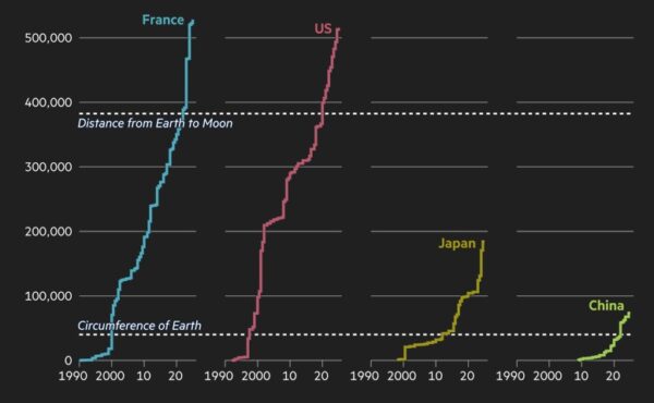
______
______
Section-6
Overview of undersea optical fiber cable:
When people communicate using wired or wireless digital devices, the information they send often traverses multiple interconnected telecommunication service networks before reaching the intended recipient. Telecommunication and internet service providers use high-capacity terrestrial (land-based) networks to carry communications within contiguous landmasses. However, to transmit communications between landmasses separated by large expanses of water, telecommunication and internet service providers rely on undersea telecommunication cables. Providers transmit voice and data communications through their terrestrial networks in the originating geography through an undersea cable to a terrestrial network in the terminating geography, which carries them to the intended recipients.
_
It all started in Britain when the successful laying of telegraph lines done on land, paved the way for undersea communications. And in 1800’s when an American-British venture successfully laid the cables across the Atlantic Ocean, it led to formal exchange of congratulatory message between US President James Buchanan and Queen Victoria hailed by a newspaper as the moment where “the Old and New Worlds are brought into instantaneous communication”. Over time, the copper cables were replaced by fibre optic cables as they were more efficient and offered more speedy transfer of data globally.
Today data in the form of video messages, photos, voice messages, emails etc, is converted into binary code (1s and 0s). For instance, when someone searches information online like about the protest in Nepal, a radio signal travels from the person’s device to a nearby mobile tower on land. From there, the signal converts into pulses of light and sent via cables to distant servers (data centres) located in some far-off locations like U.S. These servers then retrieve the data, break it into small data packets (smaller bits of data in binary code), and sends it back through the same optical route through pulses and the person gets the required information. These cables go all the way down to the ocean floor. Near coastlines, they’re buried under the seabed to keep them protected, but in the deep sea they are just laid alongside the seabed itself.
_
Texting a friend who lives overseas. Researching travel plans for your next vacation. Joining a Zoom call with an international colleague. It’s easy to take these everyday internet uses for granted when the exchange of information across continents happens so quickly. But the hidden infrastructure that enables all of this might surprise you: subsea cables that crisscross the ocean’s floor, transporting hundreds of terabytes of data per second. The industry is the “best-kept secret ever” because it’s “fairly invisible”. These underwater pipes don’t look impressive at first glance—some are no bigger than a household garden hose—but they hold the global internet together. For most internet users, undersea cables are out of sight and out of mind. Yet, these unseen conduits form the backbone of global connectivity and are a crucial part of the infrastructure that allows everyone around the world to stay in touch and share information online instantly. The next time you send an email or stream content from servers on another continent, spare a thought for the network of submarine cables that enable your digital experience.
_
Undersea cables, also known as submarine cables, are fiber-optic cables laid on the seabed between land-based stations. They are essential for transmitting telecommunication signals across oceans and seas. The first submarine cables were established in the 1850s for telegraphy, and since then, they have evolved to support high-speed internet and data communications. Today, there are over 600 commercial submarine cables stretching approximately 1.5 million kilometers globally, linking continents and facilitating everything from emails to video calls. These cables are crucial for the modern information age, as they handle about 95% of international internet traffic. They enable seamless communication, financial transactions, and access to information worldwide. The cables consist of bundles of fiber-optic strands, which are capable of transmitting hundreds of terabits of data per second. They are designed to withstand deep-sea pressures and potential damage, with protective layers of plastic, steel, and copper.
_
Submarine cable is defined as a type of cable designed for installation in deep-sea conditions, featuring a central core of optical fibers surrounded by steel wire strength members and protective layers to withstand mechanical stresses, water pressure, and environmental hazards. Subsea cables refer to underwater cables that are laid on the seabed between land-based stations to carry telecommunication signals across stretches of ocean and sea. As demand for connectivity has increased over the years, these cables have evolved to transport vast amounts of data across open waters in seconds. An undersea cable is a fiber optic cable that connects data centers across continents, enabling the synchronization of data globally for various online activities like web searches. The average person’s use of undersea cables could be as simple as performing an information search on the web. The search results are most likely provided based on data from the content provider’s local data center. However, those data centers around the world are being synchronized on a daily basis by data flowing from continent to continent on undersea fiber optic cables. The Internet Society acknowledges the work of the International Cable Protection Committee (ICPC), founded in 1958. Together with the International Advisory Body for Submarine Cable Resilience, established by the International Telecommunications Union in 2024, they are key global organizations that help identify potential ways and means to improve the resilience of this vital infrastructure that powers global communications and the digital economy.
_
Undersea cables are the main link connecting the world’s internet networks. They connect internet service providers and telecom operators everywhere with those in other countries. These cables are a few inches thick and are heavily padded to withstand the hostile environment of the sea floor. Inside, strands of fiber optic cable — similar to those that connect modern telcos’ towers and routers — provide massive capacity for large volumes of data to quickly crisscross the earth. At each “landing point,” usually a manhole covered with a lid and then topped with sand, these cables make landfall and go further inland to connect to a “landing station,” where they become accessible to major networks. These systems are critical to the modern information society.
_
Submarine telecommunications cables extend from shallow coastal waters to the deepest parts of the ocean. Approximately three quarters (74%) of these cables are located within 200 nm of the coast (the territorial seas and exclusive economic zones). The remaining 26% transit through areas beyond national jurisdiction. Currently, around 600 submarine cables are in operation, spanning all parts of the ocean except the Southern Ocean.
_
Figure below shows Subsea Cable Ecosystem:
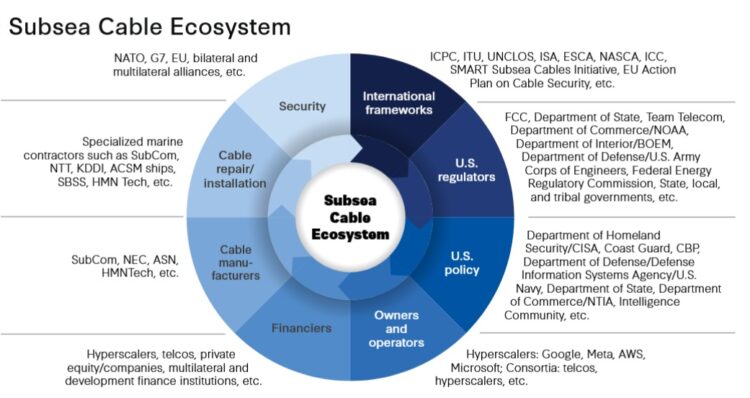
______
How Undersea Cables Work:
- Data Transmission (Fiber Optics): Information is converted into light pulses (photons) that travel through hair-thin glass strands via a process called total internal reflection.
- Capacity and Speed: These cables carry terabits of data per second (Tbps), enabling near-instantaneous global communication.
- Infrastructure: While they can be as thin as a garden hose in deep water, they are reinforced with layers of plastic, copper/aluminum (for power), and steel wire to withstand high pressure and environmental hazards.
- Power Supply: Repeaters are placed along the cable route at specific intervals to amplify the light signals, which are powered by high-voltage electricity.
- Deployment: Special ships lay these cables, which are often buried in shallow coastal waters to protect against fishing and anchoring, but simply rest on the seabed in deep,2,000+ meter, ocean areas.
These cables connect continents, facilitating the vast majority of global internet traffic, including email, social media, and financial transactions.
_
The Untold Facts of Ocean Cables:
- The first undersea cable was laid in 1858 and it carried telegraphs, not internet. It connected Ireland and Newfoundland. The message took 17 hours to transmit!
- Satellites carry less than 5% of international communication.
- Despite being more “futuristic,” satellites can’t compete with the speed and capacity of fiber optics, which carry more than 95% of all global data traffic.
- One fiber pair can handle the entire daily traffic of countries like India or Japan.
- Cable signals travel at ~200,000 km/s — 2/3 the speed of light.
- Repairs require ships to “grapple” the cable, like fishing at 5–8 km depth.
_______
Rapid data transmission:
Connecting different parts of the world through communication cables is not a new idea. In 1850, England and France were linked for the first time by an undersea telegraph cable. Since then, technology has steadily evolved, from telegraph services to telephone networks, and now to high-speed internet carried by fiber-optic cables. Today, hundreds of terabits of data pass per second through these cables laid along the seabed. Across the globe, there are over 600 commercial submarine cables, linking continents, markets, and households. Relatively thin and roughly the width of a garden hose, these cables stretch for around 1.5 million kilometres – long enough to wrap around the Earth several times. To lay them, the seabed is surveyed to find routes with fewer risks and less impact on the environment. Then, special ships unroll large reels of fibre-optic cable onto the ocean floor. Laying new cables is often a multi-year project that takes a significant amount of time. There’s extensive planning involved, and it’s usually costly too. While shorter cables cost millions, the longer ones can run into the hundreds of millions of dollars.
_
Cable traffic disrupted:
With these cables increasingly forming the backbone of the global economy, any disruption in data flow can become instantly noticeable, impacting economic activities, emergency and tech services, security systems, and internet access for billions worldwide. There are typically 150 to 200 cable incidents each year, averaging about three to four per week. In recent years, there have been quite a few high-profile incidents, from the Red Sea to West and East Africa. For example, in 2024, submarine cable incidents in the Red Sea disrupted an estimated 25 per cent of data traffic between Europe and Asia. Outages in cable connectivity may result from earthquakes, underwater landslides, and volcanic eruptions. However, statistics show that around 80 per cent of incidents are caused by human activity, from ship anchors or fishing trawlers damaging cables.
Tonga has experienced three major disruptions since 2019, caused by an earthquake, volcanic eruptions and improper anchoring. Because of the lack of a diverse network in remote regions, when a cable is cut, a vast territory can go offline.
Taiwan says it suffers seven to eight cable breaks a year, most “linked to China.” Beijing insists they are accidents. Either way, they’ve strained an already fraught relationship. Landing points and shallow waters are where cables are most vulnerable, with the Hong Tai 58 incident underscoring the challenge of policing such zones. Collecting evidence and enforcing the law are difficult as “grey zone operations” — coercive acts that stop short of war but target weak points like undersea cables — can be disguised as fishing accidents. Similar incidents in Europe and the Red Sea have raised further alarm. In December 2024, a ship departing from the Russian port of Ust-Luga dragged its anchor 90 kilometers across the Gulf of Finland, severing five data and power cables and inflicting at least €60 million ($70 million) in damage. In 2023, former Russian President Dmitry Medvedev warned on Telegram that if the West was behind the Nord Stream pipeline blasts in 2022, Moscow would have “no constraints — even moral — left” to destroy its enemies’ undersea cables.
_
Repairing the invisible highways:
Aside from abrasion and natural wear and tear, a portion of the cable infrastructure laid around the dot-com boom of 2000 is now reaching maturity, as these cables were designed for an average 25-year lifespan, In the event of an incident, engineers are usually quickly able to identify the affected area and the actual repair work itself is not always the most complicated piece. What’s often more complex is securing all the required permits and licenses, especially when multiple or overlapping jurisdictions are involved. Depending on the location and scale of damage, the summoning of cable ships and the repair work can range from days, weeks to months. In busy locations, these ships are usually close by but reaching remote areas can take longer. In many countries, the lack of a clear focal point to manage these operational requirements adds to the challenge.
_
Role of ITU:
As the UN agency for digital technologies, ITU works to enhance the resilience of global submarine cables through collaboration, standard setting, and technical guidance. Its priorities include developing resilient measures, streamlining maintenance and repair processes, and adopting more sustainable practices. Over the last 40 years, the capacity of these optical cables has been increasing by 40 per cent yearly. It’s an exponential growth which in turn powers the exponential growth of the internet. ITU isn’t an operational body and doesn’t repair cables. Instead, ITU focus on creating the right enabling environment by shortening permitting timelines, establishing clear points of contact, raising awareness to prevent accidental damage, and facilitating faster repairs. As demand for connectivity and data surge with unprecedented speed, these efforts will play a key role in bolstering the foundation for shared progress and shaping the future of the global digital landscape.
______
Cable life cycle:
The deployment, operation, and decommissioning of submarine cables follow a structured lifecycle.
- The Pre-Installation Phase focuses on route planning, environmental assessments, and surveying, ensuring that cables are strategically placed to minimize ecological impacts and avoid sensitive marine habitats.
- The Installation Phase involves cable laying and burial techniques, which may temporarily disturb the seabed and generate additional localized impacts from noise and pollution, particularly in shallow waters. The impact of this stage on coastal and marine biodiversity is primarily determined by whether a cable requires burial for protection or is surface laid (laid on the seafloor directly).
- The Operational Phase explores how cables interact with their environment over their approximately 25-year lifespan, including potential ecological interactions such as marine species colonization (“reef effect”) and risks related to abrasion and entanglement. Whilst the potential impact of this stage is low, operational cables, and the surrounding biodiversity, are not generally monitored.
- Finally, the Decommissioning Phase considers the environmental trade-offs between leaving cables in place versus active removal, assessing how each option affects seafloor ecosystems and resource recovery efforts. The pressures and impacts arising from cable removal are similar to those of the installation phase, namely, physical damage, noise and pollution.
_
Cable retirement & recycling:
There are two ends of life of a cable; there’s a physical end of life where it no longer functions and needs to be retired, and the economic end of life where it’s not worth the money to run a still functioning cable. You can have a cable that has been in the water 18 years, but because a new system gets done that’s got very similar landings the economic life of the older system is not viable. They can’t compete so for commercial reasons, even though the cable still works they will probably turn it off prematurely because it’s just not worth keeping it. The cost of maintaining at least two cable points, staff, and repair the cable as needed all represent fixed costs that make it harder to compete if a cable with more capacity follows similar routes and landing points to existing cables.
Once a cable is retired, however, there is often little effort made to recover it. While copper is valuable, it’s unlikely to recoup the cost of recovering a cable. And while many would argue leaving a cable to deteriorate in the ocean long-term is harmful, digging up a cable could also disturb any marine life in the area. Relocating cables is technically possible, but rarely happens.
_
Repurposing:
It is normally possible to increase capacity during the cable’s lifetime by modifying the land based parts of the system to provide significant increases in speed (in many cases to hundreds of times the original installed capacity). The entire wet segment, including the repeaters, are entirely agnostic with respect to the carrier signal. The number of lit wavelengths, the signal encoding and decoding, and the entire cable capacity is now dependent on the equipment at the cable stations at each end of the cable. This has extended the service life of optical systems, where additional capacity can be scavenged from deployed cables by placing new technology in the cable stations at either end, leaving the wet segment unaltered.
This means that many old cables that might have once been taken out of service and replaced with a new more capable cable can be reused in-place. For example, the Southern Cross cable has been upgraded several times. The Southern Cross Cable Network was originally designed to working with 10 Gbps DWDM and deliver 120Gbps of fully protected capacity (240Gbps across the network). On July 30, 2013, Southern Cross announced the completion of upgrade with Ciena’s 100G technology, increasing its lit capacity to 2.6Tbps and system capacity to 12Tbps. By the end of 2023, the Southern Cross Cable Network had been capable of delivering system capacity of 18 Tbps, with an active capacity of 13.4 Tbps.
_
Why new cables:
There is a consensus that bandwidth demand is doubling every two years, and hence new cables are required to keep up. But bandwidth demand is not the only reason for new cables. To understand the other reasons, we first need to distinguish between a cable’s lit capacity vs potential capacity. Lit capacity is the amount of capacity a cable is currently equipped to handle. Potential capacity, on the other hand, is the theoretical maximum capacity that a cable can support if additional capital was invested to fully equip the cable system. In most major routes, the lit share of potential capacity is less than 30%. This would suggest that we can invest in existing cables and make use of the remaining unlit capacity, but this is generally not the case.
Companies prefer laying out newer cables because they are far more technologically advanced. The unit cost is cheaper for new cables than old cables whose lit capacity is increased. In other words, new cables have better economies of scale. The second reason is that old cables have few or no spare fibre pairs. While companies can make use of the unlit capacity by sharing existing fibre pairs, content providers like Facebook, Google, Microsoft and Amazon, given their large demand, prefer buying whole fibre pairs. Other reasons for new cables include connecting some remote parts of the world that are still reliant on satellites and providing more options to economies that have only one or two cables, because any damage to these cables can cause massive disruptions.
______
Tele Geography estimates that there are 552 planned and active commercial undersea telecommunication cable systems globally (domestic and international), connecting every continent except Antarctica. Figure below shows the global distribution of cables as of May 2023.
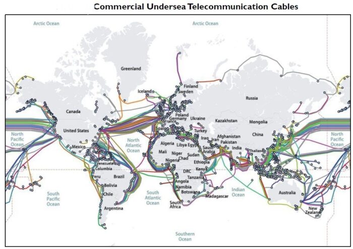
Figure above shows Commercial Undersea Telecommunication Cables.
Notes: Colors are used in the figure to visually differentiate undersea telecommunication cables in close proximity to one another. Colors may repeat in different geographic areas. The hollow circles signify cable landing stations. This map shows both domestic and international undersea telecommunication cables. Domestic undersea telecommunication cables lay point to point within a country to improve connectivity between regions within a country, and provide connectivity to the global internet. Some domestic cables cross into international waters when connecting two domestic points. International cables connect two or more countries; these enable connection between the countries and to the global internet. This map shows commercial cables and does not include all government-owned cables, such as those used for military and intelligence purposes.
There are no direct cables between South America and Australia due to their vast distances, high costs, and low traffic. Instead, the data goes through North America or Asia. The largest concentration of submarine cables is found in the Atlantic Ocean (between Europe and the US), where there are over 400 cables, and around Europe. Europe is the most “fiber-optic” continent.
_______
Capacity:
Over the past few decades, capacity on new subsea internet cables has increased from hundreds of megabits per second (Mbps) of capacity, to systems with hundreds of terabits per second (Tbps) of capacity, at present. Predictably, newer ocean internet cables are capable of carrying significantly more data than cables laid 10, 20, or 30 years ago. As an example, the MAREA submarine cable, which currently operates between Virginia Beach (United States) and Sopelana (Spain), offers 200 terabits per second (Tbps) of capacity. In comparison, Global Cloud Xchange’s FLAG Europe-Asia (FEA) undersea cable, which became ready for service (RFS) in 1997 and traverses an EMEA-to-Asia route, only provides approximately 500 gigabits per second (Gbps) of capacity. Notably, only around 30% of a submarine cable’s total design capacity is lit capacity, meaning the capacity that is being utilized by the end user. These significant capacity buffers are normal industry practice because they allow for underwater internet cable systems to respond to unexpected spikes in demand, such as carrying traffic that is rerouted from other systems following a cable fault.
Highest Capacity Submarine Cable:
Currently, the highest capacity submarine cable in operation is Google Cloud’s trans-Atlantic system called Dunant, which spans 4.1k miles (6.6k kilometers) across the Atlantic Ocean, connecting Virginia Beach (United States) with Saint-Hilaire (France). Particularly, Dunant has a capacity of 250 terabits per second (Tbps), across 12 fiber pairs. At 250Tbps, it is about to be overtaken by the search giant’s own 340Tbps UK-US Grace Hopper cable. Japanese IT multinational NEC plans to build a huge submarine cable for Facebook, with a capacity of up to 500Tbps across 24 fiber-pairs.
_______
International Submarine Cable Resilience Summit 2026:
Experts call for better protection of submarine internet cables:
As undersea cables face mounting pressure from human activity, ageing expertise, and shifting geopolitical routes, experts in Porto warned that the weakest links in global connectivity are no longer the breaks themselves, but how the world prepares for and responds to them.
A high-level panel at the International Submarine Cable Resilience Summit 2026 in Porto focused on a growing paradox in global connectivity. While submarine cable damage incidents have remained relatively stable for over a decade, the time needed to repair them has increased sharply.
Moderated by Nadia Krivetz, member of the International Advisory Body for Submarine Cable Resilience, the discussion brought together government officials and industry experts who warned that longer repair times are creating new vulnerabilities for the global internet, even as undersea cable networks continue to expand rapidly.
Andy Palmer-Felgate of the International Cable Protection Committee highlighted that more than 80% of cable damage is caused by fishing and anchoring, mostly on continental shelves where maritime activity is densest. She noted that a small number of high-risk ‘problem cables’ consume around half of the world’s annual repair capacity, suggesting that targeted prevention in specific locations could significantly reduce global disruption. Palmer-Felgate also pointed to a shift in fault patterns away from Europe and the Atlantic toward Asia, exposing weaknesses in a repair model that depends on shared, slow-to-move vessels.
New monitoring technologies were presented as part of the solution, though not without limitations. Sigurd Zhang described how distributed acoustic sensing can detect vessel activity in real time, even when ships switch off tracking systems, citing cases in which fishing fleets were invisible to conventional monitoring systems.
Eduardo Mateo added that newer optical monitoring tools can identify long-term stress and seabed instability affecting cables. Still, both speakers stressed that the cost, data complexity, and reliability requirements remain major barriers, especially for shorter cable systems.
Beyond monitoring, the panel explored improvements in cable design and installation, including stronger armouring, deeper burial, and more resilient network topologies. Mateo cautioned that technology alone cannot eliminate risk, as submarine cables must coexist with other seabed users.
Zhang noted that fully integrated ‘smart cables’ combining telecoms and scientific monitoring may still be a decade away, given the strict reliability standards operators demand.
Industry practices and skills were also under scrutiny. Jamieson argued that careful route planning and proper burial can prevent most cable faults. Still, Simon Hibbert warned that these standards depend on experienced workers whose skills are hard to replace. With an ageing maritime workforce and fewer recruits entering sea-based professions, the panel cautioned that declining expertise could undermine future cable resilience if training and knowledge transfer are not prioritised.
______
What happens if the Cables fail?
Severing transcontinental data cables would have immense consequences. If the main cable is damaged, you lose the entire Internet connectivity. If you lose the Internet connectivity, that means you lose everything. An affected region would not even be able to use its own internal network, effectively transforming it into an information vacuum. While undersea cables have built-in redundancies, their failure could still spell disaster for modern society. In a worst-case scenario, the simultaneous loss of multiple cables could sever communication between continents. This would freeze financial markets, halt international banking, and disrupt supply chains. Fortunately, these cables are designed with many backups in mind. The world’s data is distributed across multiple cable routes, and traffic can be rerouted in the event of a break. But as the 2011 Japan earthquake showed, the loss of just a few key cables can bring a country to its knees. Within hours of the quake, Japan lost seven of its 12 transpacific cables, and internet traffic slowed to a crawl as the remaining cables struggled to handle the load.
In 2006, a 7.0 magnitude earthquake off the coast of Taiwan severed eight submarine cables, causing widespread internet outages across East Asia. In 2012, Hurricane Sandy delivered a wake-up call to the industry when it knocked out several transatlantic cables, isolating North America from Europe for hours.
But most disruptions are less dramatic: a ship drops anchor in the wrong place, or a fisherman snags a cable in a trawling net.
______
Telecommunication companies (e.g., AT&T, Verizon, Deutsche Telekom, China Mobile), own and operate most undersea cables. One company or a consortium of companies may own a single commercial undersea telecommunication cable. In the late 1990s, consortia of companies and investors built undersea cables and sold the capacity to carriers. According to a report from one policy think tank, single-owner entities own around 65% of the undersea telecommunication cables, while consortia own 33%. Starting around 2015, technology companies, such as Google, Facebook, and Amazon, began investing in and building their own undersea cables, as sole owners or as parts of a consortium, to meet increasing demands.
In the United States, as well as in many other nations, repair and maintenance of commercial undersea telecommunication cables is primarily a private sector responsibility. Cable owners may develop agreements between themselves and with other infrastructure owners (e.g., offshore power transmission cable and pipeline owners). These private agreements could define the placement of the respective infrastructures; crossing notification procedures, where owners agree to install cables at minimum distances apart in locations where a cable may cross an existing undersea telecommunication cable or other infrastructure; and access agreements for maintenance and repair, to avoid harm to cables.
_______
In late 2025, the 2Africa subsea cable system, the largest open‑access undersea cable in the world, was declared complete and activated, marking a pivotal milestone for both global and African digital infrastructure. The cable spans approximately 45,000 kilometres, linking over 46 landing points in 33 countries across Africa, Europe, and Asia. With a design capacity of up to 180 terabits per second (Tbps), it surpasses all existing submarine cables serving Africa combined. This immense capacity can transform connectivity for more than 3 billion people worldwide, including Africa’s 1.4 billion residents, positioning the continent as a strategic hub for global internet traffic rather than a mere transit corridor.
Until recently, telecommunications companies were laying down most of the cables. But over the past decade, big tech giants have started taking more control. Google alone privately owns six cable systems and has invested in an additional 19 subsea cables. Amazon, Meta, and Microsoft have invested in their fair share of cable networks too. Planning, building and deploying a new cable system is an enormously complex and expensive undertaking, costing up to US$ 500 million and can take several years.
Before a cable can be laid, the sea floor needs to be mapped to determine the best possible route. That means avoiding strong currents, volcanic activity, and extreme changes in elevation. While deep down in the ocean protection is generally high, when cables approach shore additional safeguarding may be needed, such as concrete trenches.
Once a route is decided upon, cable laying vessels are sent out to sea. The loading of the cables alone can take months, as was the case for the Marea cable. That 4,104 mile (6,605 kilometers) long, just over 10 million pounds (4.6 million kilograms) heavy transatlantic cable now connects Virginia Beach in the United States with Sopelana in Spain.
______
______
Why subsea cables matter:
As of 2025, more than 550 subsea cables were in service, spanning over 1.4 million kilometers globally. These high-capacity fiber-optic cables are engineered to carry massive volumes of data at incredible speeds, enabling instant access and seamless connectivity that modern businesses and consumers rely on. With the rapid expansion of cloud computing, AI workloads, streaming services, and global e-commerce, the demand for high-capacity, low-latency connections between continents continues to accelerate. Subsea cables directly support this demand by reducing data transit times and improving network resilience. Subsea cables are critical for nearly all aspects of commerce and business connectivity. For example, one major international bank moves an average of $3.9 trillion through these cable systems every workday. Cables are the backbone of global telecommunications and the internet, given that user data (e.g., e-mail, cloud drives, and application data) are often stored in data centers around the world. This infrastructure effectively facilitates daily personal use of the internet and broader societal functions. In addition, sensitive government communications also rely extensively on subsea infrastructure. While these communications are encrypted, they still pass through commercial internet lines as data traverses subsea infrastructure. Subsea cables carry a much larger bandwidth and are more efficient, cost-effective, and reliable than satellites; consequently, they have been credited with increasing access to high-speed internet worldwide, fueling economic growth, boosting employment, enabling innovation, and lowering barriers to trade. These networks are now indispensable links for the modern world and are pivotal to global development and digital inclusivity.
_
Key Importance and Functions:
- 97% of global communications are transmitted via cables lying deep beneath the oceans.
- There is no alternative to using these undersea cables. Satellite technology cannot effectively handle the communications requirements of the modern digital economy and society. Satellites handle less than 5% – to an estimate of even 0.5% – of global data transmission, and are less efficient, slower, and more expensive. Therefore, satellites are often exclusively considered for remote areas with challenging conditions for laying submarine cables. Submarine cables are thus the essential technical infrastructure for all internet communication.
- In a single day, these cables carry some $10 trillion of financial transfers and process some 15 million financial transactions.
- They facilitate global trade, cloud services, and international financial transactions, supporting economic growth.
- They are critical for secure, high-speed government and military communication, essential for national security.
_
Most of the world’s data is managed by big tech firms including Alphabet, Meta, and Amazon, which consumed 3.6 billion megabits per second of bandwidth in 2023, according to the research firm TeleGeography. That’s roughly as much data as 700 million people streaming Netflix at the same time. The companies operate global content distribution networks, which rely on undersea cables to move data quickly around the world.
As more of the world becomes digitally connected, the need for undersea cables will only grow. Cloud computing, artificial intelligence, and the Internet of Things all require fast, reliable data transmission, making these cables more essential than ever. In fact, tech companies have taken matters into their own hands. Google alone has backed at least 14 undersea cables globally, while Amazon and Facebook have invested in others. Until not too long ago, only communication companies laid internet cables.
_____
Subsea cables and AI:
Oftentimes when people think about AI, they think about data centers, they think about compute, they think about data. But the reality is, without the connectivity that connects those data centers, what you have are really expensive warehouses. With the artificial intelligence boom, the infrastructure through which data travels has taken on more importance. There is no AI without high-speed connectivity. Although the Internet is often depicted as existing in the “cloud”, it heavily depends on subsea cables. Subsea fibre-optic cables function as the high-capacity, low-latency backbone that supports AI by enabling large-scale data transfer among global data centres. They facilitate the training of extensive AI models and connect dispersed cloud infrastructure. They transfer large datasets needed for AI model training and inference across continents. AI inferencing is the “doing phase” in which a trained machine learning model applies its learned knowledge to new, unseen data to make predictions, classifications, or decisions, turning its training into practical outcomes. These cables connect globally distributed data centres, allowing tech behemoths to manage AI workloads and localised services.
_____
Business-Critical Applications:
For certain industries and applications, understanding and selecting the right submarine cable infrastructure isn’t just a technical consideration – it’s business-critical. Here are key examples:
_
High-Frequency Trading and Financial Services:
- Every millisecond matter: A 1ms advantage can be worth $100 million annually to a major trading firm
- Location matters: Physical proximity to submarine cable landing stations can provide decisive competitive edges
- Path diversity requirements: Need multiple independent cable routes to ensure uninterrupted trading operations
- Regulatory considerations: Financial data may need to follow specific physical paths to meet compliance requirements
_
Global Content Delivery:
- Regional performance impacts user retention: 100ms of additional latency can reduce conversion rates by 7%
- Cache placement strategy depends on physical infrastructure: Optimal CDN design must account for submarine cable topology
- Traffic prioritization capabilities: Premium content may need guaranteed submarine capacity during peak viewing hours
- Burst capacity requirements: Live events require significant bandwidth that depends on submarine cable availability
_
Cloud Service Providers:
- Global availability zones depend on submarine connectivity: Cloud reliability is directly tied to physical infrastructure redundancy
- Latency consistency matters: Applications perform poorly when experiencing variable latency across submarine routes
- Data sovereignty considerations: Legal requirements may dictate which physical cables can carry certain types of data
- Disaster recovery planning: Geographic separation of backup sites must consider submarine cable diversity
_
Online Gaming Platforms:
- Regional server placement strategy: Optimal locations depend on submarine cable topology
- Latency thresholds for playability: Most competitive games require <100ms ping, directly impacted by cable routes
- DDoS protection capabilities: Need providers with significant submarine capacity to absorb attack traffic
- Global tournaments require special provisioning: Major events need guaranteed performance across multiple continents
_
Telehealth and Remote Services:
- Video quality requirements: HD medical imaging needs consistent submarine capacity
- Reliability requirements: Cannot tolerate outages for critical care applications
- Growth planning: Expansion to new regions depends on available submarine infrastructure
- Backup connectivity: Critical services need diverse submarine routes for failover
_____
International security:
Submarine communication cables are a critical infrastructure within the context of international security. Transmitting massive amounts of sensitive data every day, they are essential for both state operations and private enterprises. One of the catalysts for the amount and sensitivity of data flowing through these cables has been the global rise of cloud computing.
The U.S military, for example, uses the submarine cable network for data transfer from conflict zones to command staff in the United States. Interruption of the cable network during intense operations could have direct consequences for the military on the ground.
The criticality of cable services makes their geopolitical influence profound. Scholars argue that state dominance in cable networks can exert political pressure, or shape global internet governance.
An example of such state dominance in the global cable infrastructure is China’s ‘Digital Silk Road’ strategy funding the expansion of Chinese cable networks, with the Chinese company HMN Technologies often criticised for providing networks for other states, holding up to 10% of the global market share. Some critiques argue that Chinese investments in critical cable infrastructure, being involvement in approximately 25% of global submarine cables, such as the PEACE Cable linking East Africa and Europe, may enable China to reroute data traffic through its own networks, and thus apply political pressure. The strategy is countered by the U.S., supporting alternative projects.
______
______
Benefits of Submarine Communication Cables:
Following are the benefits or advantages of Submarine communication cables:
-1. Undersea cables can withstand rocky sea beds, marine animals, tsunamis, volcanoes, and even the occasional shark attack.
-2. Designed for high bandwidth and low latency.
-3. Offer high reliability and greater security due to the difficulty of tapping into them.
-4. Very cost-effective compared to satellites.
-5. Optical fiber cables offer low power loss and are immune to electromagnetic interference.
-6. Greater tensile strength compared to copper fibers of the same dimensions.
-7. Flexible and lighter in weight.
-8. Essentially non-polluting.
-9. Undersea cable networks are designed to last for around 25 years.
Drawbacks of Submarine Cables:
Following are the drawbacks or disadvantages of Submarine cables:
-1. Not suitable for regions vulnerable to disasters like mudslides or typhoons, where satellites are a better option.
-2. Not ideal for remote villages, terrains, small island nations, and hilly regions.
-3. Installation is slow, tedious, and expensive.
-4. Repairs can be time-consuming.
-5. Continuous threats from shipping and fishing activities.
-6. Require repeaters at regular intervals to boost the signal.
-7. Potentially used for espionage by countries during wartime.
-8. Costly, requiring significant investment for fiber network installation.
______
______
Number, distribution and spread of subsea internet cables:
Over the past three decades, an invisible infrastructure revolution has been unfolding far beneath the seas. Since roughly 1995, the world has added almost a million miles of deep-sea submarine cables, enough to wrap around the equator 35 times. These cables carry thin strands of fibers not much wider than a human hair which ferry internet traffic as light signals across continents, spanning ocean floors and connecting people all over the world. They allow you to send text messages to relatives on the other side of the planet or watch a video filmed thousands of miles away. More subsea cables are coming as seen in figure below.
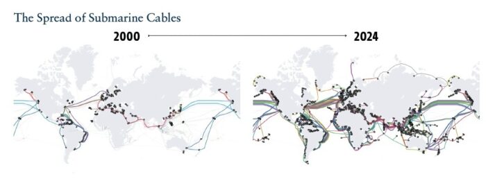
Figure above shows spread of submarine cables.
The rise of artificial intelligence will only increase the world’s insatiable demand for data. Right now, about half the world’s data centers—which are essential for AI— are in North America and Western Europe, drawing much of the world’s internet traffic. Tele geography, a telecommunications data provider, anticipates that investment in subsea cable infrastructure will exceed $13 billion in the 2025-2027 period, roughly twice the level of investment in 2022-2024.
_
Unequal spread of subsea cables:
As of 2023 there were more than 500 communications cables at the bottom of the ocean, but a quick glance at the map of the world’s undersea cable networks shows they are largely centred around economic and population centres. The unequal spread of cables is clearest in the Pacific, where a territory like Guam, with a population of just 170,000 and which houses a US naval base, has more than 10 internet cables connecting to the island. New Zealand, with more than 5 million people has seven. Tonga has just one. In the aftermath of the 2022 eruption in Tonga, governments across the world were spurred into action, commissioning reports into the vulnerabilities within the existing undersea cable network, while tech companies worked to bolster networks to ensure such an event never occurred again. For now, the economic fundamentals favour the building of more cables across the western world and into emerging markets, where the digital demand is booming. Despite the warnings of sabotage or accidental damage – experts say that without the market imperative to create more resilient networks, the real risk is that places like Tonga will continue to go dark, threatening the very promise of digital equity that the internet was founded on.
_
The growth of global Internet traffic has driven a drastic expansion of the submarine cable network, both in terms of the sheer number of links and its total capacity. Today, a complex mesh of hundreds of cables, stretching over one million kilometres, connects nearly every corner of the earth and is instrumental in closing the remaining connectivity gaps.
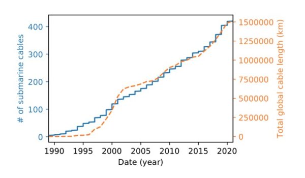
Figure above shows Number of active submarine cables based on their ready for service dates (RFS) (left axis). Total length of currently active submarine cables by year (right axis). Includes planned cables for future activations through 2020.
_
Number of cables worldwide:
The number of submarine cables worldwide has grown steadily over time. Here is a list of the number of cables in service over the last decades.
Year Number of submarine cables in service
1989 3
1994 37
1999 103
2004 169
2009 241
2014 318
2019 398
2020 419
2021 436
2022 459
Undersea cables lifetime:
Submarine communications cables are designed to last about 25 years. However, their lifetime depends on their revenues. So, if operational costs exceed revenues, they might be decommissioned ahead of time.
_
A visible trend has emerged in the expansion of submarine cable projects into new and increasingly contested geographic regions for example the launch figures in developed Asia–Pacific increased rapidly, from 21 in 2020 to 33 in 2023, while those in emerging Asia–Pacific increased from 26 to 38. According to Analyst Mason between 2010 and 2023, Western Europe saw the highest number of new submarine cable launches, totalling 77 followed by Emerging Asia–Pacific with 71 new cables, developed Asia–Pacific having 68. Other regions included North America with 45, the Middle East and North Africa with 44, Sub-Saharan Africa with 30, Latin America with 28, and Central and Eastern Europe with 7 new cables. The data and the ready for service map (below) shows that the most planned/in deployment cables can be found in developed and emerging Asia–Pacific region.
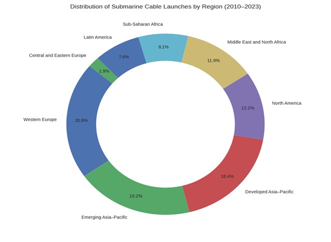
_____
_____
Types of Undersea Communication Systems:
- Transoceanic (5,000 – 13,000km)
– High Capacity Pipes
– Connections between Continents
- Regional/Festoon networks (< 5,000km)
– Connecting regional locations, with ROADM nodes
– Nested branches, perhaps with mesh networks
– Concatenation of systems via terrestrial bypasses
- “Repeaterless” links (<500km)
– No electrical power in the undersea cable
– Systems connecting Islands, or perhaps locations along the coast
__
Modern, deep-sea communication cables often use lightweight armored (LWA) or lightweight (LW) designs for flexibility, while shallow, high-risk areas use heavily armored (single/double) cables. They are critical for transoceanic internet connectivity. These are classified by the level of protection needed against fishing, anchors, and ocean currents:
- Lightweight (LW) Cable: Used for deep ocean waters (2,000m to 8,000m) where there is low risk of damage.
- Lightweight Protected (LWP) Cable: Similar to LW, but with additional anti-wear protection.
- Single Armored (SA) Cable: Used in intermediate depths (500m to 2,000m), offering moderate protection.
- Double Armored (DA) Cable: Designed for shallow, high-risk areas (0m to 500m) near shores to protect against anchors and trawlers.
_
In 1985, the first deep-water repeatered design was laid off the Canary Islands. By 1988, the first trans-Atlantic fibre-optic cable (TAT-8) had been installed, followed several months later by the first trans-Pacific system. Such cables usually had two or more pairs of glass fibres. Originally, a pair could transmit three to four times more than the most modern analogue system. Today, a cable with multiple fibre-optic pairs has the capacity for over 1 million telephone calls. Despite this greatly enhanced capacity, modern cables are actually much smaller than analogue predecessors. Deep-ocean types are about the size of a garden hose (17–20 mm diameter), and shallow-water armoured varieties can reach up to 50 mm diameter. This means that instead of making four or five ship voyages to load and lay an analogue cable across the Atlantic, only one or two voyages are now required for fibre-optic types. It also means that the footprint of the cable on the seabed is reduced (AT&T, 1995).
_
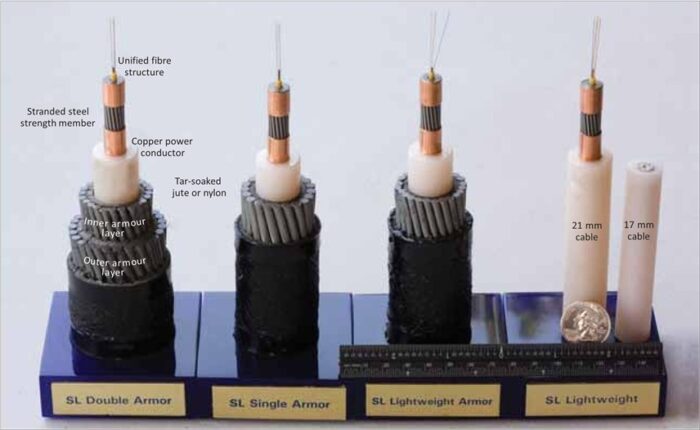
Figure above shows: Shallow- to deep-water (left to right) fibre-optic cables, with a core supporting pairs of hair-like optical fibres surrounded by a layer of wire to provide strength, a copper conductor to power the repeaters or amplifiers that process the light signal, and a case of polyethylene dielectric. Wire armour is added for protection.
_
Multiple types of submarine cables may be used in a submarine cable system, subject to depth of the seabed where the cable lies as seen in figure below.
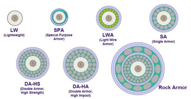
The double armored submarine cable is used at the shore-end, terminated at the beach manhole at the cable landing site, and is interconnected with much lighter land cable going onward to the cable landing station.
_
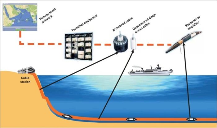
Figure above shows a submarine cable system with armoured cable near shore and unarmoured cable in seabed at depth.
_
Submarine internet traffic relies on specialized undersea cables composed of strands of silica glass fiber optics. These cables are meticulously designed to cater to global connectivity demands. Submarine networks make use of various optical fiber types like G.652, G.653, G.656, and G.663, selected to fulfill specific requirements. The majority of these cables design life is 25 years. These cables may incur attenuation losses within the range of 0.15 dB/km to 0.17 dB/km, necessitating signal amplification for effective long-distance data transmission. To address this challenge, active repeaters are strategically incorporated along the cable’s span, typically positioned every 50 to 150 kilometers, adapting to varying data rates. While signal power requirements are relatively low, high voltages (up to 10-15kV DC, sometimes higher) are necessary to overcome resistance over thousands of kilometers.
______
______
Submarine power cable:
By definition, submarine power cables carry high-voltage electricity beneath seas and oceans, enabling the connection of different electrical grids and infrastructure across the sector. A submarine power cable is a transmission cable for carrying electric power below the surface of the water. These are called “submarine” because they usually carry electric power beneath salt water (arms of the ocean, seas, straits, etc.) but it is also possible to use submarine power cables beneath fresh water (large lakes and rivers). Examples of the latter exist that connect the mainland with large islands in the St. Lawrence River.
From a structural point of view, it is mainly divided into three-core submarine cables and single-core submarine cables. Most of the medium and low-voltage lines use three-core submarine cables, and most of the high-voltage lines use single-core submarine cables.
From a functional point of view, half a century ago, the submarine cable only had a simple power transmission function, and now the submarine cable integrates two functions, effectively realizing the transmission of power and signals on the same cable.
From the perspective of insulation composition, it is divided into oil-filled insulated submarine cables and extruded plastic insulated submarine cables.
From the perspective of load type, it can be divided into DC submarine cable and AC submarine cable. DC submarine cable is characterized by low loss and easy to realize long-distance power transmission. However, the application experience of DC submarine cable is not rich. The cost is high, and the loss of the AC submarine cable is large, but the operation and maintenance technology is mature, and the supporting construction cost is small.
Typically, these cables range from 70mm to over 210mm in diameter and are available in two types: alternating current (HVAC) and direct current (HVDC). The choice depends mainly on the route length, voltage, transmission capacity and synchronisation with the grid. Generally, alternating current is more cost-effective for distances under 80km, while direct current technology offers better performance for longer distances. Increasingly higher voltages are being introduced to extend their reach.
Undersea internet (telecommunications) cables and power cables both lie on the seabed but differ significantly in purpose, construction, and operation. Internet cables use fiber optics to transmit data via light, are thinner, and require repeaters to boost signals. Power cables are much larger, heavily armored to transmit high-voltage electricity, and use converter stations rather than repeaters.
Hybrid submarine cables are specialized undersea cables that combine high-power electrical transmission and fiber-optic data communication within a single, durable casing. These composite cables power subsea installations (such as offshore wind farms, oil/gas rigs, and ocean sensors) while simultaneously transmitting data back to shore. They reduce installation costs and allow for efficient, long-distance power and data delivery in harsh environments. Two services, one installation means cost savings and reduced operative exposure to harsh environments.
_______
_______
Different cables and different routes:
Submarine cables connect continents and their countries, mainland to islands, islands to each other, or several points along a coast. As such, undersea cables are interconnecting locations that have a coastline but do not share land borders, for example, between the United States and the United Kingdom. The top 100 subsea cable systems in the world are categorized into the following six geographic segments: Trans-Atlantic, Trans-Pacific, Intra-Asia, U.S.-Latin America, Europe-Asia, and Africa.
Major global subsea cable routes, by region, are as follows:
- Trans-Atlantic: New York to London (most competitive route globally)
- Trans-Pacific: Los Angeles to Tokyo, Los Angeles to Hong Kong, Los Angeles to Singapore, Los Angeles to Sydney
- Americas: Miami to São Paulo, Miami to Fortaleza (Brazil), New York to São Paulo
- Intra-Asia: Tokyo to Singapore, Hong Kong to Singapore, Singapore to Mumbai
- EMEA-to-Asia: London to Singapore, Marseille to Mumbai (higher latency routes)
- Europe to Africa
_
Below is an example of Google Cloud connecting its data center in Northern Virginia (left) to another one of its data centers in Belgium (right), via a trans-Atlantic submarine cable, landing on the west coast of France.
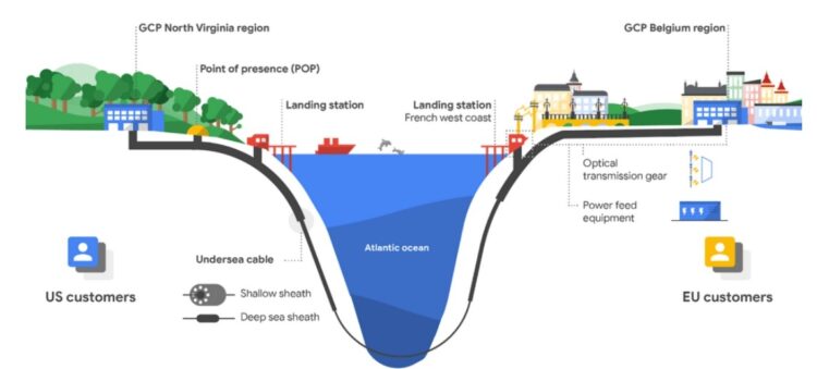
Figure above shows transatlantic cable Google Cloud’s Dunant.
_
The TeleGeography Cable Map 2024 records 559 cable systems and 1,636 landings that are currently active cables and planned cables. Additionally, almost 82% of the world’s inter-regional bandwidth connects to the U.S. and Canada via fiber optic cables. Subsea cables span the world’s oceans, creating an undersea infrastructure that links continents and major economic hubs.
Here’s a breakdown of where these cables are primarily located:
-1. Atlantic Ocean: A dense concentration of undersea cables crosses the Atlantic, particularly between the eastern United States and Western Europe. This route is one of the oldest and most heavily used. Transatlantic cables support high-speed connections between tech and financial centers like New York, London, and Frankfurt.
-2. Pacific Ocean: Several major cables run between North America, Asia, and Oceania, linking countries like the United States, Japan, South Korea, and Australia. These routes support communication and data flow across the world’s largest ocean, connecting significant tech and economic regions.
-3. Indian Ocean: The Indian Ocean hosts key cables connecting Asia, the Middle East, and Africa. These cables play an important role in linking countries like India, the United Arab Emirates, and South Africa, enabling data transfer across emerging markets and global supply chain routes.
-4. Regional Seas: Many cables are installed in regional seas such as the Mediterranean Sea, the North Sea, and the Caribbean Sea to support localized connectivity between nearby countries. For example, cables in the Mediterranean link Europe to North Africa and the Middle East, while cables in the North Sea connect the UK to mainland Europe.
-5. Coastal Waters and Landing Stations: Undersea cables also extend into coastal waters where they connect to landing stations. Coastal landing stations point where cables come ashore and link to terrestrial networks. These landing stations are typically located near major cities or data hubs to facilitate high-speed data transmission inland.
Submarine cable hubs are strategic locations where multiple undersea cables converge, creating high-capacity data exchange points essential for global connectivity. These hubs are typically located in coastal cities with well-developed telecommunications infrastructure, such as New York, London, Singapore, and Tokyo.
_
Table below shows 25 largest submarine cable systems in the world as of 2025:
|
|
Subsea Cable |
RFS |
Kilometres |
|
1. |
Southern Cross NEXT |
2022 |
15840 |
|
2. |
Bifrost |
2024 |
16460 |
|
3. |
Africa Coast to Europe (ACE) |
2012 |
17,000 |
|
4. |
Echo |
2024 |
17,184 |
|
5. |
América Móvil Submarine Cable System-1 (AMX-1) |
2014 |
17,800 |
|
6. |
Trans-Pacific Express (TPE) |
2008 |
17,968 |
|
7. |
Asia Connect Cable-1 (ACC-1) |
2025 |
18,000 |
|
8. |
SEA-ME-WE 4 |
2005 |
18,800 |
|
9. |
Asia-Pacific Cable Network 2 (APCN-2) |
2001 |
19,000 |
|
10. |
SEA-ME-WE 6 |
2025 |
19,200 |
|
11. |
South American Crossing (SAC) |
2000 |
20,000 |
|
12. |
Asia-America Gateway (AAG) |
2009 |
20,000 |
|
13. |
SEA-ME-WE 5 |
2016 |
20,000 |
|
14. |
Japan-U.S. Cable Network (JUS) |
2001 |
21,000 |
|
15. |
Pacific Crossing-1 (PC-1) |
1999 |
21,000 |
|
16. |
TGN-Pacific |
2002 |
22,300 |
|
17. |
GlobeNet |
2000 |
23,500 |
|
18. |
South America-1 (SAm-1) |
2001 |
25,000 |
|
19. |
Asia Africa Europe-1 (AAE-1) |
2017 |
25,000 |
|
20. |
Hawaiki Nui |
2025 |
26,000 |
|
21. |
FLAG Europe-Asia (FEA) |
1997 |
28,000 |
|
22. |
Southern Cross Cable Network (SCCN) |
2000 |
30,500 |
|
23. |
EAC-C2C |
2002 |
36,500 |
|
24. |
SEA-ME-WE 3 |
1999 |
39,000 |
|
25. |
Africa-2 |
2023 |
45,000 |
_
Meta’s proposed “Project Waterworth” is slated to become the world’s longest subsea fiber-optic cable, spanning over 50,000 km (31,000 miles) and connecting the US, India, Brazil, and South Africa to support AI infrastructure. Currently, the 2Africa cable (45,000 km) is recognized as the longest, connecting 33 countries across Africa, Europe, and Asia. Unlike SEA-ME-WE 6, it comprises multiple segments rather than a single continuous system. The SEA-ME-WE 6 (Southeast Asia-Middle East-Western Europe 6) is currently the longest continuous undersea cable in operation. Spanning approximately 19,000 kilometres, it links Southeast Asia, the Middle East, and Western Europe. Key landing points include Singapore, Malaysia, Saudi Arabia, Egypt, and France. The cable was developed to meet the increasing demand for global data transmission and is a cornerstone of international communication infrastructure. With its vast capacity, SEA-ME-WE 6 ensures seamless data flow for billions of users worldwide.
______
______
Long-Haul Undersea Networks:
The economics of long-haul undersea links is similar to that of the long-haul terrestrial links, but with a few subtle differences. First, there are several types of undersea links commonly deployed. One type spans several thousands of kilometers across the Atlantic or Pacific oceans to interconnect North America with Europe or Asia, as shown in Figure below. Another type tends to be relatively shorter haul (a few hundred kilometers), interconnecting countries either in a festoon type of arrangement or by direct links across short stretches of water. The term festoon means a string suspended in a loop between two points. In this context, it refers to an undersea cable used to connect two locations that are not separated by a body of water, usually neighboring countries. A trunk-and-branch configuration is also popular, where an undersea trunk cable serves several countries. Each country is connected to the trunk cable by a branching cable, with passive optical components used to perform the branching at the branching units. If a branch cable is cut, access to a particular country is lost, but other countries continue to communicate via the trunk cable. WDM is widely deployed in all these types of links.
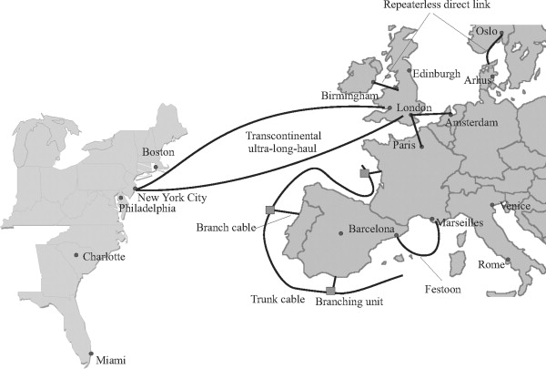
Figure above shows different types of undersea networks, showing a couple of ultra-long-haul trans-Atlantic links, shorter-haul direct repeaterless links, a trunk-and-branch configuration, and a festoon.
Undersea systems are designed to provide very high levels of reliability and availability due to the high cost of servicing or replacing failed parts of the network. Optical amplifiers with redundant pumping arrangements have proven to be highly reliable devices, and their failure rates are much lower than those of electronic regenerators. Likewise, optical add/drop multiplexers using passive WDM devices have been qualified for use in undersea branching configurations.
One key difference between undersea links and terrestrial links is that, in most cases, undersea links are deployed from scratch with new fibers rather than over existing fiber plant. It is rare to upgrade an existing long-haul amplified undersea link, as the cost of laying a new link is not significantly higher than the cost of upgrading an existing link. This provides more flexibility in design choices.
______
______
Cost of submarine cable and internet:
Prices vary significantly based on several factors like cable length, capacity, water depth, and route complexity. On average, expect costs to start around $40,000 per mile (roughly $25,000 per kilometer) for manufacturing and installation alone. A full-scale transoceanic cable, stretching thousands of kilometers across the seabed, can quickly tally up to between $250 million and $400 million. Costs range from roughly $6,000 to over $40,000 per kilometer, for example, the 21,700km SEA-ME-WE 6 system costing approximately $500 million.
Building these systems requires enormous capital investments. A transatlantic cable spanning 7,000 kilometers costs around $250 million, while trans-Pacific routes can reach $400 million. The cable itself varies dramatically in cost—from $6,000 to $20,000 per kilometer—depending on factors like the number of fiber pairs (now typically 16-24 pairs) and armouring requirements near shore where cables face the highest risk of damage from fishing activities and ship anchors. Repeaters add another $200,000 each, with dozens required for transoceanic routes. Landing stations can cost millions more, though operators can save money by using existing facilities. Beyond hardware, projects require years of planning, environmental surveys, and navigating complex permitting processes across multiple jurisdictions. The total price includes optical repeaters, branching units, cable landing station equipment, marine environmental surveys, permitting, and the substantial costs of specialized installation vessels.
Who foots the bill for these massive projects? Traditionally, telecom companies have teamed up in a consortium to share the costs and benefits. These consortiums still exist, but there’s a new trend: private investors—particularly tech giants like Google, Microsoft, Meta, and Amazon—are now investing directly in submarine cables to strengthen their global networks.
Hybrid models are increasingly common, too, where consortiums, private companies, and even governments pool resources to improve connectivity, especially for regions that need an economic boost.
_____
Internet cost and subsea cables:
So far, however, much of that investment has focused on strengthening existing links between already well-connected areas, particularly between North America, Europe and East Asia. Africa and Latin America, although better connected than in the past, still have far fewer direct links to major data hubs. In most cases, a group of telecom companies such as Orange, Sparkle, or Axiata or major players such as Google or Meta will own the cable and sign leases with local internet providers for access.
This matters because of the widening gap in online access, not because broadband connections aren’t available, but because they are still an expensive luxury. Subscriptions in wealthier countries typically cost less than 1 percent of an average monthly income (in terms of GNI per capita) for both mobile internet services and fixed-line service, according to the International Telecommunications Union (ITU), a United Nations agency. In low-income countries, those figures jump to 6 percent and nearly 26 percent respectively, levels that only a small share of users can afford and which lie well above the ITU’s 2 percent affordability target (Figure below). Sub-Saharan Africa has some of the highest internet prices of any region in the world. A fixed internet subscription there costs nearly a fifth of an average monthly income.
_
The High Cost of Fast Internet
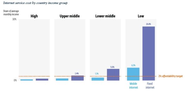
Figure above shows Internet service cost by country income group.
Note: The 2% affordability target, established by the International Telecommunications Union (ITU), suggests that the cost of internet services should ideally not exceed 2% of average monthly income. This benchmark is used to assess whether broadband access is financially sustainable.
_
And although mobile phones have become widespread in low- and middle-income countries, many of those phones are not connected to the internet. For instance, roughly 56 percent of the population in low-income countries has a mobile phone but only 27 percent have mobile broadband subscriptions. Roughly one out of three people globally still have no internet subscription.
That can have broader economic consequences. Banking services, government aid, health information or civic participation increasingly rely on the internet. Being online helps businesses reach customers or get access to market prices or other critical information. A 10 percent increase in internet use in a country is associated with a rise in average per-capita GDP of 0.8 percent for fixed-line, home internet services and 1.6 percent for mobile internet services, according to a recent study.
Expanding the reach of subsea cables can help bring the internet to more people. Doubling the capacity of these cables can lower internet prices in a country by as much as 30 to 50 percent, according to recent IFC research as seen in the figure below.
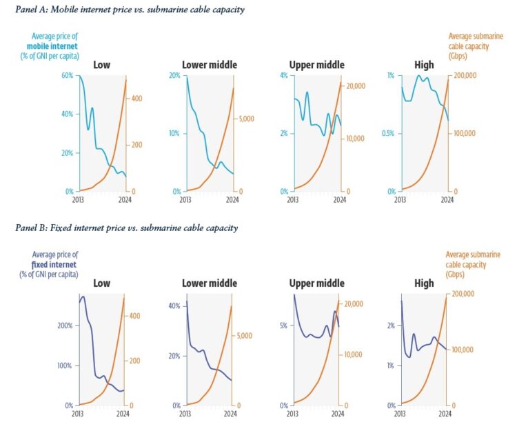
_
More subsea internet Cables, Lower internet Costs:
More cables mean more internet traffic can be carried simultaneously, or more capacity is available per person, improving user experience while also lowering costs for telecom operators and their customers.
New undersea cable connections also make it possible for traffic to move between noncontiguous countries, without having to rely on more expensive underground cables, some of which may travel through multiple countries incurring fees along the way. For landlocked countries, this dependency on neighboring coastal nations often results in higher costs and limited access to international bandwidth. Strengthening cross-border fiber networks and ensuring open access to submarine cable landing stations could help reduce these barriers, making connectivity more affordable and inclusive. And having multiple subsea cables connect to a country makes that country’s network connections more stable and resilient, which lowers maintenance costs. If one cable breaks, others pick up the slack, avoiding the need for costly emergency repairs.
_
There’s also evidence that having more undersea cable capacity encourages governments and private operators to invest in the rest of the internet supply chain, such as by expanding underground fiber-optic networks between cities or building more transmission towers or Wi-Fi hubs in remote villages. Other studies found that firm innovation and entrepreneurship rise following the arrival of subsea cables through the substantial additional capacity they deliver, and that higher internet penetration thanks to the cables boosts real per-capita GDP and productivity. Evidence from Africa shows that the arrival of fast internet due to the first submarine connections increased employment rates by up to 13 percent and improved firm productivity by 13 percent in manufacturing sectors. It also supported shifts toward higher-skill occupations and reduced job inequality.
_
But there’s a catch: In countries where the provision of subsea capacity is inappropriately regulated or limited to single players, adding more undersea cables can make the fixed and mobile broadband markets more concentrated, according to IFC research. This happens because dominant providers can gain control over the new infrastructure, allowing them to block competitors and tighten their grip on the market. As a result, over time, the effect of adding more capacity on prices weakens. Prices may experience a slight drop but over time they stabilize or even creep upward as the market becomes less competitive.
For governments, therefore, it makes sense to use the regulatory system to keep the local internet market competitive. That would give providers an incentive to offer better quality service at lower prices and thereby bring more customers online. An expanding market, in turn, would likely draw more investment towards undersea cables, although those decisions are also heavily influenced by global connectivity needs and strategic considerations.
______
______
Arctic:
Subsea cables in the Arctic are emerging as critical infrastructure for global connectivity, aimed at linking Europe to Asia and North America via shorter routes while improving network resilience. Due to the low population density and harsh environment, businesses in the Arctic have historically been unable to make strong cases for connectivity infrastructure investment. Major projects like Far North Fiber and Polar Connect are currently developing routes through the Arctic Ocean, aiming for faster, more secure data transmission compared to traditional paths, though they face challenges from harsh conditions and regional security concerns. The climate change induced melting of Arctic ice has provided the opportunity to lay new cable networks, linking continents and remote regions. Several projects are underway in the Arctic including 12,650 km “Polar Express” and 14,500 km Far North Fiber.
The melting of ice caps in the Arctic has opened new possibilities for undersea cable routes, sparking competition between nations like Russia and Canada for control over these strategic corridors. The Arctic Internet Corridor represents a potential new frontier for global connectivity, offering shorter and more efficient routes between Europe, Asia, and North America.
However, the development of these routes comes with environmental and geopolitical challenges. The melting ice caps raise concerns about climate change and its impact on Arctic ecosystems. Additionally, the competition for control over these routes highlights the ongoing geopolitical tensions between major powers seeking to assert their influence in the region.
______
Antarctica:
Antarctica is the only continent not yet reached by a submarine telecommunications cable. Phone, video, and e-mail traffic must be relayed to the rest of the world via satellite links that have limited availability and capacity. Bases on the continent itself are able to communicate with one another via radio, but this is only a local network. To be a viable alternative, a fiber-optic cable would have to be able to withstand temperatures of −80 °C (−112 °F) as well as massive strain from ice flowing up to 10 metres (33 ft) per year. Thus, plugging into the larger Internet backbone with the high bandwidth afforded by fiber-optic cable is still an as-yet infeasible economic and technical challenge in the Antarctic.
______
______
Alternatives to subsea internet cables:
The importance of the international subsea cable network cannot be understated. The cables carry about 95% of all global Internet traffic. Additionally, $10 trillion of financial transactions flow over them per day. Even with that, this infrastructure is often ignored or overlooked until there’s a serious problem — like the recent cable disruptions in the Red Sea. Those disruptions are bringing satellite and cross-continent cables into focus. Until now, these approaches have been relegated to special use cases for a number of reasons.
Satellite data transmission services typically cost more to send data than if it is done over Internet subsea cables. Additionally, many satellite services have lower bandwidth compared to the subsea cables. And then there is the issue of latency. A signal is sent to a satellite in geostationary earth orbit (GEO), and then back down to an Earth substation takes about 250 milliseconds. That’s enough for a noticeable delay in real-time communications. In contrast, a transmission between the Middle East and, say, India carried over a subsea cable would take about one-tenth that time because of the significantly shorter distance the signal traverses.
Still, satellite services are starting to target specific routes to provide an alternative to subsea cable. One such recent offering is from CMC Networks, a global Tier 1 service provider serving Africa and the Middle East. Recently a company began satellite connectivity services across Africa and the Middle East to keep African businesses connected to the internet during subsea cable outages. In doing so, it tried to address the latency issues of satellite communications by including Low Earth Orbit (LEO) and Medium Earth Orbit (MEO) connectivity to the more common GEO satellite connectivity to its portfolio of solutions. The LEO and MEO services do not have the latency issues of GEO services.
The other alternative is to build and use more cross-continent cables.
One challenge with such cables is that many permits are often required to build a single cable due to it crossing many jurisdictions. Another challenge is the massive amount of work needed to plan, dig trenches, lay cable, and bury every foot of the length of the cable. One needs to consider the 40-plus years of trouble providers have had to deploy fiber-to-the-home to get an appreciation of the scope of the issue.
Besides the issue of potential subsea cable disruptions, cross-continent cables are getting a closer look due to shifting traffic patterns. In China and India, 48% of Internet traffic is now cross-continent, according to the ITU.
_______
_______
FAQ:
How many cables are there?
As of 2026, we track more than 600 active and planned submarine cables. The total number of active cables is constantly changing as new cables enter service and older cables are decommissioned.
Do the cables actually lie on the bottom of the ocean floor?
Yes, cables go all the way down. Nearer to the shore cables are buried under the seabed for protection, which explains why you don’t see cables when you go to the beach, but in the deep sea they are laid directly on the ocean floor. Of course, considerable care is taken to ensure cables follow the safest path to avoid fault zones, fishing zones, anchoring areas, and other dangers. To reduce inadvertent damage, the undersea cable industry also spends a lot of time educating other marine industries on the location of cables.
How many kilometers of cable are there?
As of early 2025, there are over 1.48 million kilometers of submarine cables in service globally. Some cables are pretty short, like the 131-kilometer CeltixConnect cable between Ireland and the United Kingdom. In contrast, others are incredibly long, such as the 20,000-kilometer Asia America Gateway cable.
How much information can a cable carry?
Cable capacities vary a lot. Typically, newer cables are capable of carrying more data than cables laid 15 years ago. The new MAREA cable is capable of carrying 224 terabits per second (Tbps).
Why don’t companies use satellites instead?
Satellites are great for specific applications. Satellites do an excellent job of reaching areas that aren’t yet wired with fiber. They are also helpful for distributing content from one source to multiple locations. However, on a bit-for-bit basis, there’s just no beating fiber-optic cables. Cables can carry far more data at a fraction of the cost of satellites. Statistics released by U.S. Federal Communications Commission indicate that satellites account for just 0.37% of all U.S. international capacity.
What about my mobile device? Isn’t that wireless?
When using your mobile phone, the signal is only carried wirelessly from your phone to the nearest cell tower. From there, the data will be carried over terrestrial and subsea fiber-optic cables.
Sharks are known for biting cables. Is that true?
According to data from the International Submarine Cable Protection Committee, fish bites (a category that includes sharks) accounted for zero cable faults between 2007 and 2025. The majority of damage to submarine cables is caused by human activities, primarily fishing and anchoring, rather than sharks.
What happens to cables when they are old and turned off?
Cables are engineered with a minimum design life of 25 years. Cables may remain operational longer than 25 years, but they’re often retired earlier because they’re economically obsolete. They can’t provide as much capacity as newer cables at a comparable cost, and are thus too expensive to keep in service. When a cable is retired, it could remain inactive on the ocean floor. Increasingly, companies are acquiring the rights to cables, pulling them up, and salvaging them for raw materials. In some cases, retired cables are repositioned along other routes. To accomplish this task, ships recover the retired cable and then re-lay it along a new path. New terminal equipment is deployed at the landings stations. This approach can sometimes be a cost-effective method for countries with minor capacity requirements and limited budgets.
How are undersea fiber optic cables laid on the ocean floor?
Undersea fiber optic cables are laid using specialized cable-laying ships. These vessels position themselves at the designated starting point of the cable route and deploy the cable into the water. As the ship moves forward, the cable is paid out from a cable carousel and lowered to the ocean floor. Trenching operations may be conducted to bury the cable for protection.
How are undersea fiber optic cables repaired if they get damaged?
When undersea fiber optic cables are damaged, specialized repair vessels are deployed to the affected area. These vessels use remotely operated vehicles (ROVs) to locate and assess the damage. Repairs can involve splicing in new sections of cable, repairing faulty repeaters, or replacing damaged components. The repaired cable is then carefully reinstalled and buried in the seabed as necessary.
Can water damage fiber optic cables?
Water alone does not damage fiber optic cables. In fact, the cables are designed to be waterproof and protected from the external environment. However, external factors such as fishing activities, natural disasters, or physical disturbances can potentially damage the cables. Regular maintenance, proper installation, and protection measures ensure the long-term integrity and performance of undersea fiber optic cables.
What happens if an undersea cable is cut?
If an undersea cable is cut or damaged, it can result in disruptions to communication and data transmission. Repair and maintenance vessels are quickly dispatched to the affected area to locate and fix the fault. While repairs are being carried out, traffic may be rerouted through alternate cables or satellite links to minimize service disruptions.
Can undersea fiber optic cables be upgraded to support higher speeds?
Yes, undersea fiber optic cables can be upgraded to support higher speeds and greater capacity. Upgrades can involve replacing or adding equipment at the cable landing stations and implementing advanced transmission technologies. These upgrades allow network operators to meet the growing demand for higher bandwidth and accommodate future advancements in data transmission.
What is the frequency of inspection for subsea cables?
It is highly recommended to have an inspection every 6-12 months for a platform along with continuous sensor-based monitoring to detect anomalies.
How much downtime does a submarine cable damage have on average?
Conventional repairs take 4-6 weeks to complete. New technologies such as ROVs and pre-deployed repair kits have considerably reduced this time.
______
______
Section-7
Submarine fiber-optic cable system:
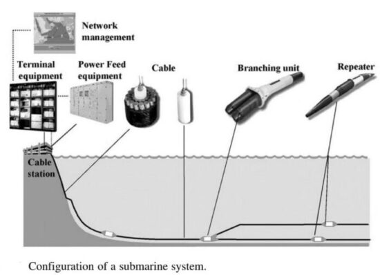
_
When most people think of the internet, they picture wireless signals and satellites floating far above the earth. But the real backbone of global connectivity is quietly hidden beneath the ocean waves: the vast network of submarine fiber optic cables. Today, there are around 600 active submarine cable systems crisscrossing the oceans, totaling over 1.5 million kilometers. If you can picture stretching fiber optic cables around Earth’s circumference 35 times—that’s basically what this impressive network achieves! These undersea highways are the lifelines of the digital world, physically connecting continents, countries, and billions of people. Without them, your international emails, video calls, and streaming services would grind to a halt.
_
Of course, not all oceans have equal cable coverage. The busiest cable routes connect the major economies and digital hubs. Across the Atlantic Ocean, cables like MAREA (owned by Microsoft and Meta) and Dunant (owned by Google) connect North America and Europe with lightning-fast speeds of over 200 Tbps each. Likewise, across the Pacific Ocean, cables such as FASTER (linking the US to Japan and Taiwan) and PLCN (connecting the US with Hong Kong and the Philippines) bridge North America to Asia—spanning incredible distances of up to 13,000 kilometers.
_
Beyond these transoceanic giants, numerous regional systems provide essential connectivity within specific areas. Southeast Asia, for example, relies heavily on regional cables due to its numerous islands and coastal communities. One of the most exciting regional expansions underway is 2Africa, became fully operational in 2024 stretching 45,000 kilometers—making it one of the longest submarine cable systems ever built—and will connect an incredible 34 countries across Africa, Europe, and Asia.
_
As global internet usage continues to skyrocket (international bandwidth demand grew at an annual rate of 45% between 2017 and 2021), cable operators are constantly expanding and upgrading the network. While brand-new cables are always being installed, operators frequently boost existing cable capacity by upgrading terminal equipment—allowing them to keep pace with demand without laying entirely new routes.
Because cable faults and breaks occasionally occur, network redundancy is crucial. Cable planners make sure each region has several cable connections—if one cable gets damaged, traffic reroutes through alternative paths, avoiding disruptions. Think of redundancy as having backup highways when your main commute route is blocked.
_
Deepest cables in the Mariana Trench:
Undersea cables have also been laid in some of the world’s deepest and most difficult locations, including the Mariana Trench. These cables are built to withstand the intense pressure and extreme conditions found at depths of over 10,000 metres. The cables in these deep-sea regions have advanced materials and reinforced armouring to ensure they can operate without failure, even in the most challenging environments.
Cables close to shore are typically buried, “offering a layer of protection” from damage, and cables that lay directly on the seabed are somewhat protected, because of their deep sea location and because their exact location is not publicly disclosed.
_
Cables can interconnect with each other and with terrestrial networks, forming the backbone of the global internet. This interconnection provides owners with alternate paths to reroute traffic if a cable is damaged. It also means that damage to a cable in one location could affect service to other cables serving other locations.
The United States has high network redundancy. The number of licensed undersea telecommunications cable landing stations rose from 52 in 2004, to 74 in 2019, to 85 in operation or planning to enter service as of May 2023. The AEP Team asserts that in the United States, owners have access to a relatively large number of cables, providing opportunities to reroute traffic to alternate paths in case of cable damage. They also note that there is a concentration of cable landing sites in a few physical locations, creating the potential for a single attack or natural event (e.g., hurricane) to affect multiple cables at once, which could cause long-term communication disruptions for many.
__
Where Sea meets Land at Cable Landing Stations:
You might wonder how these extraordinary underwater cables connect seamlessly to the land-based internet networks we use every day. That vital connection happens at specialized facilities called cable landing stations.
Cable landing stations are coastal buildings that house critical equipment allowing the transition from submarine to terrestrial fiber networks. Inside these secure facilities, you’ll find power feed equipment (PFE) supplying electricity to repeaters along the cable route, optical distribution frames organizing all the fiber connections, and submarine line terminal equipment (SLTE) converting optical signals into electrical signals for use in terrestrial networks. Since landing stations represent such crucial infrastructure, security is tight. Expect perimeter fences, restricted access, surveillance cameras, and sometimes even guards. Despite their importance, most landing stations intentionally blend into their surroundings so as not to draw unwanted attention.
_____
_____
Dry and wet plant:
A complete undersea telecommunication cable system includes fiber-optic cable encased in layers of material (e.g., plastic, steel, aluminum) for protection from water damage and for insulation. The cable is laid on the ocean floor and connects two or more onshore cable landing stations. The cable landing station typically contains transmission, reception, power, and network management equipment. The fiber-optic cable may include repeaters within the cable that boost transmitted signals and branching units that allow a cable to serve multiple end-points as seen in figure below.
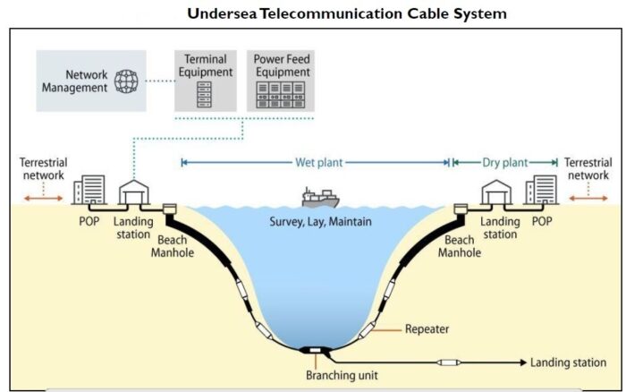
Figure above shows Undersea Telecommunication Cable System.
Figure above shows an undersea telecommunication cable system, including cable landing stations and equipment (e.g., terminal equipment and power feed); undersea cable (with repeaters, and a branching unit) running from beach manhole to beach manhole; and fiber lines from the cable landing station to a point-of-presence that connects via fiber to inland terrestrial networks. The terrestrial portion of an undersea telecommunication cable system called the “dry plant,” and the undersea portion called the “wet plant.”
POP = point-of-presence. Point of Presence (PoP) is a physical location that houses data center.
_
A Submarine Cable System is comprised of a cable laid beneath the water that carries telecommunication transmission signals between two or more cable landing stations containing equipment that converts submarine cable signals to terrestrial signals. The Wet Segment of the Submarine Cable System makes landfall at the Beach Manhole (BMH) or beach joint that, in turn, connects to the Dry Segment and Submarine Cable Landing Stations (CLS). The Wet Segment lies between Beach Manholes, including submarine cables, repeaters, branching units. While the Dry Segment includes a short cable from a Beach Manhole to a Submarine Cable Landing Station (CLS) and system components installed in the CLS.
_
Dry Plant:
The dry plant is the terrestrial segment of an undersea cable system, running from a cable landing station to the beach manhole. A cable landing station is typically a few hundred meters from the beach manhole near the shoreline and connected by a short, repeater-less fiber link.
_
Beach Manhole:
The beach manhole is a “concrete chamber, buried into the beach, or road behind the landing point, where the submarine cable is terminated and from where the [fiber cable and power cable] are routed to the [cable landing station]. Most manholes are designed to take more than one cable, most commonly two. Fiber connects the cable landing station to a beach manhole, where it joins the undersea cable.
_
Cable Landing Station:
A cable landing station is an on-shore facility where undersea cables arrive and terminate. Cable landing stations contain submarine line terminal equipment (SLTE) that can transmit and receive signals. They receive signals from the undersea cable and transmit signals inland to terrestrial networks, usually through a provider’s point-of-presence (POP) or interconnection facility, and can receive signals from terrestrial networks and transmit them to undersea cables. Since a POP could be hundreds of miles from the seashore, operators often use a longer fiber link with repeaters to connect to the cable landing station.
To transmit signals, electronically controlled semiconductor lasers (laser diodes) transmit signals by modulating (i.e., pulsing) light and sending it into the optical fiber. To receive signals, semiconductor optical detectors receive the light from the fiber, modulate the signals to produce a corresponding electrical signal, and transmit the signal to a provider’s POP or interconnection facility, which transmits the signal to the provider’s terrestrial telecommunications network.
Cable landing stations may also contain network management systems that allow operators to monitor and control cable operations and traffic, and power feed equipment (PFE) that provides a constant direct electrical current through the cable to power repeaters.
You can’t visit a landing site or a data centre without noticing the need for power, not only for the racks but for the chillers: the cooling systems that ensure that servers and switches don’t overheat. And as the submarine cable landing site has unusual power requirements for its undersea repeaters, it has rather unusual backup systems, too.
_
A Submarine Cable Landing Station (CLS) is a dry land facility where submarine cables terminate traffic, allowing voice, data, and internet to be transmitted to terrestrial or local networks. At the terminal, equipment such as Submarine Line Terminal Equipment (SLTE), converts cable signals to terrestrial signals allowing the cable to interconnect to terrestrial facilities.
Traditionally, a CLS and a Data Center where a Point of Presence (PoP) is located are different facilities, interconnected through a Backhaul system. Figure below shows the CLS houses SLTE, PFE (Power Feeding Equipment), Backhaul terminals and other network components.
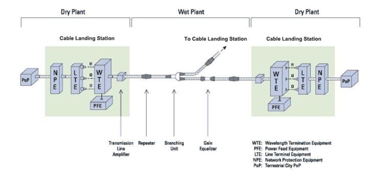
_
Nowadays, Cable Landing Station (CLS) and Data Center (PoP) are typically merged. CLS becomes part of a data center, or CLS within a Data Center. It is now more popular for a submarine cable system to terminate at a carrier-neutral data center, with both SLTE and PFE housing at a CLS within a Data Center.
When Open Cable structure becomes popular, the functionality of a Cable Landing Station (CLS) is typically reduced, to house only the PFE and the Open Cable Interface of a submarine cable system, with SLTEs housing in a data center or multiple data centers, as shown in the following figure.
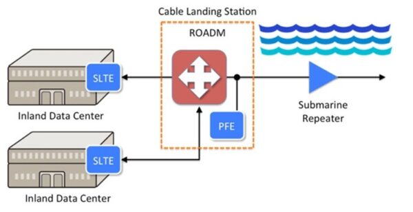
Multiple submarine cable systems may share the same cable landing station.
In most of the jurisdictions worldwide, the construction, land and operation of a submarine cable system is strictly regulated. Submarine Cable Landing License and other license/permits are required prior to lay and land a submarine cable within a territory waters.
__
SLTE:
Submarine Line Terminal Equipment (SLTE) is the critical, specialized hardware located at both ends of a subsea cable system within a landing station (the “dry plant”). It converts terrestrial network signals into optical signals suitable for long-distance, high-capacity transmission through fiber-optic cables on the ocean floor.
- Function: SLTE drives the light signals onto the cables, acting as the interface between the submarine cable and terrestrial networks.
- Components: It consists of high-capacity optical transponders, transceivers, and multiplexers (MXPonders).
- Performance: Modern systems, often provided by companies like Ciena and Nokia, support 100+ wavelengths per fiber pair, aiming for 100-400 Gbps per wavelength.
- Open Cable Model: With the rise of “open cables,” SLTEs are increasingly being housed in vendor-neutral data centers rather than just the cable landing station, allowing operators to choose their own terminal equipment.
SLTE maximizes the efficiency and capacity of submarine cables, which are vital for intercontinental data, voice, and internet traffic. It bridges the gap between the submarine infrastructure and terrestrial networks, enabling global communication.
______
Wet Plant:
A subsea cable comprises two plants; the wet plant and the dry plant. The wet plant is anything that touches the sea. The dry plant is anything located on land. The wet plant comprises the actual cable, the repeaters (technically, the amplifiers) and the BU (branching unit). The wet plant is the segment of the cable system that runs from a beach manhole on one landmass to a beach manhole on another. Installation of new cables often requires boring and trenching to place the manhole on or near the seashore and drilling beneath the beach to lay feeder pipes to carry cables into the water. Special cable-laying ships, often equipped with a plough to dig a trench in the seabed in which to lay cable, continue the installation from shore to shore.
_
Testing submarine cables:
To one side is a bench of test equipment and, as seeing is believing, one of the technicians plumbs a fibre-optic cable into an EXFO FTB-500. This is equipped with an FTB-5240S spectrum analyser module. The EXFO device itself runs on Windows XP Pro Embedded and features a touchscreen interface. After a fashion it boots up to reveal the installed modules. Select one and, from the list on the main menu, you choose a diagnostic routine to perform.
______
Open cable system:
An open cable system is a submarine network model allowing owners to mix and match wet plant (undersea cable) with different terminal transmission equipment (SLTE) vendors, offering greater flexibility and lower costs than traditional closed, single-vendor systems. It enables providers to choose their own coherent optical modems, facilitating independent upgrades and improved capacity.
- Flexibility & Cost: Allows purchasers and internet content providers (ICPs) to select terminal technology separately from the submarine cable.
- Technology Upgrades: Facilitates faster adoption of new, high-capacity technology.
- Open Landing Stations: Neutral, multi-party access to submarine cables, promoting competition and network resilience.
- Example Project: Sparkle’s GreenMed project highlights this approach, enabling tenants to select preferred optical vendors.
The benefits of Open Cables have been touted extensively in the industry. One often highlighted benefit is the enablement of independent vendor selection for wet plant and SLTE, allowing best of breed utilization on two very critical pieces of the subsea network.
Since SLTE technology cycles are typically faster than a Submarine cable build cycle, and chip generations are inherently staggered in timing across multiple DSP vendors, this independent selection allows absolute maximization of cable capacity at the time of cable RFS.
_______
_______
Repeater (optical amplifier):
Undersea repeaters represent one of the most critical yet least visible components of global telecommunications infrastructure. These sophisticated devices enable the transmission of data across vast ocean distances, connecting continents and making modern internet communication possible. More than 95% of intercontinental internet traffic travels through undersea fiber optic cables, and repeaters are the vital amplification stations that keep signals strong across thousands of kilometers of ocean floor.
_
An undersea repeater is essentially a pressure-sealed housing containing optical amplifiers that regenerate weakened optical signals as they traverse the ocean floor. Unlike terrestrial optical amplifiers that can be easily accessed for maintenance or replacement, undersea repeaters must operate continuously for 25 years at depths reaching 8,000 meters or more, under pressures exceeding 800 atmospheres, in complete darkness, and without any possibility of repair without a costly cable ship intervention.
_
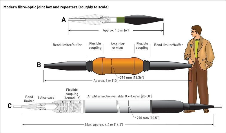
Figure above shows representative repeaters from different manufacturers. The housings can accommodate as many as eight individual regenerators, or more recently, optical amplifiers for each fiber pairs.
_
The fundamental purpose of an undersea repeater is to compensate for signal attenuation that occurs as light travels through optical fiber. Even with the highest quality fiber, optical signals degrade over distance due to various loss mechanisms. In a typical transoceanic cable system spanning 10,000 kilometers, signals might pass through 100 to 150 repeaters, each precisely amplifying the weakened optical carriers back to usable power levels.
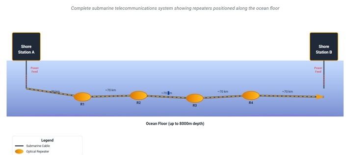
_
Erbium-Doped Fiber Amplifiers (EDFA):
As early as 1985, advances in optical amplifiers were being made that would eventually find their way into submarine cables. That was when a physics grad student named Robert Mears did experiments with erbium-doped glass fibers and showed that they could act as purely optical, low-noise amplifiers in the wavelengths typically used for communications. Within ten years of the first paper on the subject, erbium-doped fiber amplifiers (EDFAs) were slipping into the Atlantic on the TAT-12/13 cable.
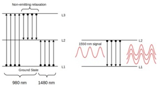
Figure above shows that EDFA works by exciting a population of erbium ions to a higher energy state with a 980 nm or 1480 nm pump laser, and forcing that population to relax with an incident 1550 nm signal photon. This stimulates the emission of a lot of 1550 nm photons as the erbium electrons relax.
Like many devices we use every day and tend to take for granted, EDFAs leverage the principles of quantum physics and yet are surprisingly simple. EDFAs rely on the fluorescent properties of oxides of the rare-earth element erbium to achieve amplification. When a small amount of erbium (III) oxide is added to the core of a silica fiber, the electrons in the erbium ions can be excited from their ground state (L1) by hitting them with laser light at a specific pumping wavelength. The pumping laser can either be 980 nm, which excites the erbium electrons to the L3 state, or 1,480 nm, which excites them to the L2 state. Practical EDFAs tend to use both 980 and 1,480 nm pumping lasers.
Excitation by the pumping laser leaves the erbium-doped fiber with a population inversion, which is a state where more atoms are in the excited state than the ground state. This creates a medium that’s ripe for disruption, specifically by the passage of a photon at a specific wavelength. For the excited erbium ions, that’s about 1,550 nm, which just so happens to be the wavelength of the infrared lasers used to send signals down an optical cable. When 1,550 nm photons hit the excited erbium ions, it induces them to return to their ground state, releasing a photon of the same wavelength in the process. Each relaxation releases a photon, each of which has the same wavelength and same phase as the incident photon and is traveling in the same direction, which results in massive amplification of the incoming 1,550 nm signal.
In theory, EDFAs are extremely simple — just a loop of doped fiber 10 to 20 meters in length, a laser diode for pumping, and the necessary optical components to join the amplifying loop to the incoming and outgoing fiber and multiplex the two together. The only electronics needed are those that drive the pumping diode, plus whatever circuits are needed for monitoring the health of the amplifier and controlling it remotely.
Real-world EDFAs are a bit more complex, tending to have a host of other optical components, like isolators on the input and output fibers that prevent unwanted reflections from leaking back from the output side. Even with these elaborations, though, EDFAs are simple enough to be manufactured as compact modules which can be installed in rack-mount enclosures — at least for amplifiers for land-based fiber optic cables.
_
Without repeaters, undersea fiber optic communication would be limited to a few hundred kilometers at most. The combination of fiber attenuation, chromatic dispersion, and other transmission impairments would render long-distance communication impossible. Modern repeaters using erbium-doped fiber amplifiers have enabled the explosion of global internet connectivity by:
- Amplifying optical signals transparently without electrical conversion
- Supporting wavelength-division multiplexing with 80+ simultaneous channels
- Operating continuously for 25 years without maintenance
- Withstanding extreme pressures up to 1000 atmospheres
- Functioning in near-freezing water temperatures around 1-5°C
- Enabling multi-terabit capacity on single cable systems
_
Modern undersea repeaters use erbium-doped fiber amplifiers as their core amplification technology. An EDFA consists of a length of optical fiber whose core has been doped with erbium ions. When these ions are excited by pump light at 980 nm or 1480 nm wavelengths, they can amplify signals in the 1525-1568 nm C-band range through stimulated emission.
The amplification process works through these key steps. First, pump light from laser diodes excites erbium ions from their ground state to higher energy levels. Signal photons at 1550 nm interact with excited erbium ions, causing stimulated emission of additional photons at the same wavelength and phase. This results in optical gain, typically 10-15 dB per repeater, achieved with low noise figure around 4.5-5.0 dB. The process is transparent to data rate and modulation format, and supports simultaneous amplification of multiple wavelength channels.
The quantum mechanical process underlying EDFAs relies on the electronic energy level structure of erbium ions in silica glass. The metastable excited state has a relatively long lifetime of approximately 10 milliseconds, which allows for population inversion and efficient amplification.
_
Technical Specification: Typical EDFA Parameters:
- Gain: 10-15 dB per stage
- Output Power: +12 to +17 dBm
- Noise Figure: 4.5-5.0 dB
- Gain Bandwidth: 30-40 nm (C-band: 1525-1568 nm)
- Pump Wavelength: 980 nm (most common for low noise)
- Pump Power: 100-500 mW per amplifier
- EDF Length: 10-30 meters
_
Modern optical fiber repeaters use a solid-state optical amplifier, usually an erbium-doped fiber amplifier (EDFA). Each repeater contains separate equipment for each fiber. These comprise signal reforming, error measurement and controls. A solid-state laser dispatches the signal into the next length of fiber. The solid-state laser excites a short length of doped fiber that itself acts as a laser amplifier. As the light passes through the fiber, it is amplified. This system also permits wavelength-division multiplexing, which dramatically increases the capacity of the fiber.
_
Repeaters are powered by a constant direct current passed down the conductor near the centre of the cable, so all repeaters in a cable are in series. Power feed equipment (PFE) is installed at the terminal stations. Typically both ends share the current generation with one end providing a positive voltage and the other a negative voltage. A virtual earth point exists roughly halfway along the cable under normal operation. The amplifiers or repeaters derive their power from the potential difference across them. The voltage passed down the cable is often anywhere from 3000 to 15,000V DC at a current of up to 1,100mA, with the current increasing with decreasing voltage to maintain constant power; the current at 10,000V DC is up to 1,650mA. Hence the total amount of power sent into the cable is often up to 16.5 kW.
_
Submarine fiber has attenuation. Nominal loss of fiber 0.155dB/km at 1550nm (TeraWave® SCUBA Ocean Optical Fiber). In practical scenario, it can vary and may be up to 0.25dB/km or more due various factors.
- Repeaters are used for optical signal amplification. Repeaters are placed every 60km to 70km.
- Power to the repeater is fed from Power feeding equipment, which is located in Submarine Cable Station.
- In traditional subsea cable, every fiber pair will have their own repeaters. Four fiber pairs will have repeater housing four amplifier chassis. One Amplifier chassis has Dual laser 980nm Pump Units. This is called 2×2 Pump redundancy. These types of redundancy scheme used in the past.
In traditional Subsea cable, Single pump failure of EDFA (Erbium Doped Fiber Amplifiers) putting entire fiber pair under great risk. If dual pump fails, resulting in entire repeater failure, which heavily affects live traffic in particular fiber pair of the entire segment
2×2 Pump redundancy
Here one amplifier pair i.e. two EDFAs (Transmit and receive direction), shares power from two pump lasers. This is high risk. If single pump fails, it is risk. If both pump fails, then entire repeater failure resulting in traffic impact.
4×2 redundancy
Currently, this scheme is being used. This improves the reliability by having additional 2 pump lasers compared to 2×2 pump redundancy.
Two EDFAs share the power from four pump lasers, which tolerates three-pump lasers failure at most in each fiber pair. This design doubles the total cost of pump lasers.
Above-mentioned redundancy schemes are standard. Pump powers dedicated to 1 fiber pair. The pumps cannot be shared to other fiber pair.
Repeater Pump farming:
This is the latest advancement in repeater technology. All new Subsea cables will use this type of technology, which provides maximum redundancy and flexibility. A series of pump lasers and EDFAs are cross connected via two-stage optical fiber couplers. The repeaters cross connected to each other, supporting the same group of fiber pairs. This serves the obvious: redundancy, and consequently, reliability, even in the case of multiple repeater failures. This is highly complex design.
__
Optical Signal-to-Noise Ratio: The Critical Performance Metric:
The optical signal-to-noise ratio is the most important performance parameter for undersea optical transmission systems. OSNR quantifies the ratio between signal power and optical noise power within a reference bandwidth, typically measured in a 0.1 nm (12.5 GHz) bandwidth at 1550 nm.
EDFAs introduce noise through amplified spontaneous emission. Even in an ideal amplifier, quantum mechanics dictates a minimum noise figure of 3 dB, corresponding to the addition of one photon of noise per photon of signal gain. Practical amplifiers have noise figures of 4.5-5 dB due to component losses and imperfect population inversion.
For a chain of N identical amplifiers, each with gain G and noise figure NF, the cumulative OSNR at the output can be approximated by the formula: OSNR = (Pout / N·NF·hν·B0), where Pout is the amplifier output power, h is Planck’s constant, ν is the optical frequency, and B0 is the reference bandwidth. This shows that OSNR degrades linearly with the number of amplifiers, making noise accumulation a fundamental limit for long-haul systems.
Modern coherent detection systems using advanced modulation formats like 16-QAM or 64-QAM require OSNR values of 15-25 dB or higher for error-free operation. This requirement drives the entire system design, from repeater spacing to amplifier output power to fiber type selection.
_
Submarine repeaters are the backbone of international internet connectivity. They enable high-speed data transfer across continents, supporting cloud services, streaming, and online commerce. By 2025, innovations such as integrated power management, AI-driven diagnostics, and enhanced durability are expected to further improve their performance and lifespan. Their deployment is becoming more strategic, aligning with the expansion of undersea infrastructure projects worldwide.
Researchers use submarine repeaters to transmit data from underwater sensors studying climate change, marine biology, and seismic activity. These devices enable continuous, high-fidelity data collection from remote ocean regions. The adoption of AI-enabled repeaters is increasing, allowing for autonomous diagnostics and maintenance, which reduces operational costs and enhances data reliability.
______
______
Unrepeatered cables:
Given the distances associated with transoceanic cables, from roughly 6,000km transatlantic to roughly 10,000km transpacific, there’s no choice but to use repeaters. However, for shorter distances, say a few hundred kilometers, you can submerge submarine cables, albeit without repeaters, which are commonly referred to as “unrepeatered” submarine cables. They’re also commonly referred to as passive, festoon, or single-span-loss cables. Unrepeatered submarine cable systems are fiber optic links spanning shorter distances (typically 100–300 km, up to 500+ km) that do not require submerged active amplifiers (repeaters).
Unrepeatered cables are commonly used to cross much shorter submarine distances, such as across lakes, rivers, fjords, or straits. They can include passive Branching Units (BUs) as well, to interconnect multiple shoreline locations in what’s commonly called “festoon” networks.
_
Fiber:
Most of the time, line fiber used in unrepeatered systems is of standard type, either non-dispersion shifted (NDSF, G.652) or pure silica core (PSCF, G.654). Usually, PSCF is preferred for very long links owing to its low loss at 1550 nm (typically 0.172 dB/km cabled against 0.194 dB/km for NDSF).
Chromatic dispersions of both fibers are close (typically 18.6 ps/nm.km for PSCF and 16.7 ps/nm.km for NDSF). These large values require transmitters which can cope with a large amount of chromatic dispersion or use of compensator in the system. Note that a beneficial effect of this large chromatic dispersion is that it reduces four-wave mixing and cross-phase modulation effects in multi-channels transmission. By contrast the G.653 (DSF) and G.655 (NZDSF) fibers are not well suited for repeaterless applications due to their higher loss and lower dispersion, even if long spans are possible with adequate system design.
_
Unrepeatered submarine cables commonly use (very) high-power optical amplifiers to launch at maximum allowable power levels, without damaging (melting) the fiber itself, and optical amplifiers at the receiving end such as EDFAs, Raman amplifiers, or Remote Optically Pumped Amplifiers (ROPA) to increase received power levels such that signals received can be successfully terminated. Similar to repeatered submarine cables, there are performance trade-offs associated with unrepeatered submarine cables, primarily related to achieving maximum reach and maximum capacity. Unrepeatered submarine cables can achieve multiple terabits per second of capacity over hundreds of kilometers, although the performance will be application-dependent, same as for repeatered submarine cables.
_
Optical post- and pre-amplifier:
The optical amplifier can enlarge the optical signals without the regeneration. In addition, the network upgrading is more cost-effective with optical amplifier. Each optical amplifier has an important factor which is operation gain measured in dB. The operation gain of the optical amplifier should be carefully calculated to ensure the network performance.
Pre-Amplifier is usually installed at the receiver end of the DWDM network to amplify the optical signal to the required level to ensure that it can be detected by the receiver.
Booster Amplifier (post-amplifier) is installed in the transmitting end of the fiber optic network, which can amplify the optical signal launched into the fiber link. It is usually used in DWDM network where the multiplexer attenuates the signal channels.
Optical amplifier can help to amplifier the optical power during long haul transmission to ensure that the receiver can detect the optical signal without error.
Optical post-amplifiers bring a straightforward improvement of the distance by amplifying the signal launched into the line fiber. The use of post-amplifiers is the most obvious and attractive option to increase the achievable distance, as they directly increase the power budget without degrading the receiver sensitivity, as long as non-linear effect thresholds are not crossed.
Powerful 980 nm or 1480 nm semiconductor diodes to activate erbium-doped fiber allow to achieve output powers up to +24 dBm in a cost-effective way. Furthermore amplifiers based on erbium-ytterbium doped fiber can yield power over +33 dBm. However, the power which can be launched in the fiber is limited by non-linear effects. For single channel systems, the dominating limitation is the self phase modulation induced by Kerr effect. In this case, the maximum launch power over standard fiber is typically +18 dBm for NRZ modulation format but larger powers can be launched by using a combination of fibers in the line. For WDM systems, the limitation due to crossphase modulation becomes predominant and the power per channel has to be reduced.
Optical pre-amplifiers are introduced into the systems to improve the terminal sensitivity by masking the electronics receiver thermal noise. Their design requires an optimization different from that of the post-amplifier one, the most important feature being the noise figure whose reduction leads to better system performances. The best noise figures are obtained with 980 nm pumping and can be as low as 3.5 dB, whereas 5 dB is usually obtained with 1480 nm pumping.
The optical pre-amplifier has to be combined with a narrow filter in order to filter the large noise spectrum generated by the amplifier. The optimization of the filter bandwidth has to take into account the transmitter linewidth and the non-linear effects which can broaden the signal spectrum. Filters in the range 0.2 nm to 0.5 nm are typically used.
_
Distributed Raman amplification.
In order to extend achievable distances with local optical amplifiers, a further scheme consists in using distributed Raman post-amplification, distributed Raman pre-amplification or a combination of both.
The principle is to launch a large pump power at around 1450 nm into the line fiber. Thanks to Stokes wave generation in the Silica, amplification is provided to the signals around 1550 nm. By using a pump power of 1 W at the receive end of the system, this scheme improves the achievable distance by typically 45 km (or allows to increase the system capacity by a factor of 6), without changing the outside plant. Very large power pump sources used for this application are themselves based on Raman effect internally and are therefore called Raman pumps.
_
Remote optical pump amplifier:
The remote optical pump amplifier (ROPA) consists of a piece of erbium doped fiber located about 100 km away from the terminal. The doped fiber amplifies the signal owing to the pump power which is sent from the receive terminal. As there is no electrical power feeding, this system does meet the definition of unrepeatered systems. Such a scheme can be practically implemented owing to the availability of very powerful 1480 nm pump sources (conventional pumping) and will also benefit from third order technique. The location of the ROPA is chosen in order to optimize the power budget and to guarantee system margins.
This technique has been already deployed worldwide and leads to ultimate capacity and reach of repeaterless systems.
__
The typical order of introduction of optical amplifiers is shown in Figure below, from the shortest to the longest distance.
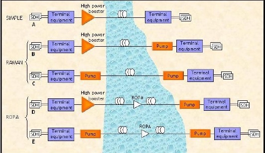
Figure above shows Optical amplification configurations.
Configuration A uses the line terminal equipment plus an optical post-amplifier at transmitter side.
Configuration B uses a Raman pump to perform distributed Raman pre-amplification.
In Configuration C, the booster is replaced by a Raman pump for distributed post-amplification.
Configuration D uses a Raman pump to activate a remote amplifier located more than 100 km away from the receive terminal.
In Configuration E, both Raman post-amplification and remote pre-amplification are used.
Depending on span at stake, amplifiers and Raman pumps are introduced into the system in a progressive manner which strikes the best balance between the overall solution performances and costs.
_____
_____
Section-8
Submarine cable transmission vs satellite transmission:
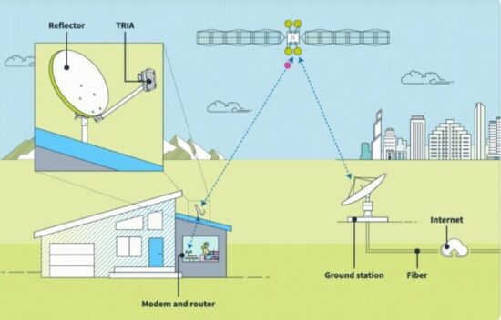
Rather than traveling through underground cables, satellite internet is internet service that’s beamed from satellites in orbit as seen in the figure above. A dish receiver mounted at your home (usually on your roof) picks up the signal and sends it to your modem to be translated into a usable internet connection. The best part about satellite internet is its availability. Since the signal comes from space, it can be picked up anywhere in the world, provided you have a clear view of the sky. This makes satellite internet an ideal choice—and often the only choice—for people in rural areas that lack cable or fiber access. The geo-stationary satellites typically used for communication are a very long way from Earth, over 35,000km high, which means that sending data one way is 70,000km, and round trip is 140,000km. That’s a lot of delay (called latency) even at light speed, which makes any real time communication very difficult.
_
Satellite internet delivers connectivity by transmitting data between a dish at your location and a satellite orbiting the Earth. It functions as a three-part relay system that bypasses the need for ground-based infrastructure like cables or fiber lines, making it a viable option for remote or rural areas.
The process involves a constant back-and-forth communication loop between three key points:
Your Location: A satellite dish, often called a VSAT (Very Small Aperture Terminal), is installed at your business to send and receive data signals.
Space Satellite: A geostationary satellite orbiting approximately 22,000 miles above the Earth receives these signals and relays them back down.
Ground Station: A Network Operations Center (NOC) on the ground receives the signal from the satellite, connects it to the global internet, and sends data back along the same path.
Because the signal must travel this vast distance to space and back, satellite internet inherently has higher latency (delay) compared to terrestrial connections.
_
Satellite’s work by beaming information through space, relaying radio frequency (RF) signals from satellite to satellite, and/or moving with the rotation of earth to compensate for the curve of the earth, as well as sending signals to the ground. Most are in a Low Earth Orbit (LEO), 99 to 1,200 miles above earth, though some reside in Geosynchronous Equatorial Orbit (GEO), about 22,000 miles above earth. There is a longer communication time lag (latency) the farther away a satellite is from earth. Many critical communication satellites reside in LEO, and the space is getting crowded. The U.S. Federal Communications Commission (FCC) has authorized SpaceX to fly 30,000 satellites in LEO. They have a short orbital period, between 90 and 120 minutes, meaning they can travel around the planet up to 16 times a day.
_
Satellite internet requires an unobstructed path between your antenna and the satellite to function, as obstacles like trees, mountains, or buildings block the microwave signals. The antenna must have a clear “look angle” to the sky. Geostationary (GEO) is fixed in one spot; requires a precise, unchanging, unobstructed line of sight.
Low Earth Orbit (LEO) is fast-moving, requiring a clear, wide view of the sky to allow the antenna to track satellites as they move across the sky. Starlink requires a clear, unobstructed line of sight to the sky to function properly. The antenna needs a wide-angle, roughly 100 to 110-degree field of view to track moving low-Earth orbit satellites. Any obstruction—trees, buildings, or rooflines—will cause service interruptions, such as slow speeds or dropped video calls.
_
Musk said SpaceX satellites are “especially for those where connectivity is nonexistent, too expensive or unreliable.” Satellites also have the advantage of distributing content from one source to multiple locations. Then there is 5G—the fifth-generation mobile network. To fulfill their role in 5G, communication companies need stable access to a satellite spectrum in LEO. Satellite internet provides broadband connectivity primarily to remote, rural, and underserved areas, bypassing the need for terrestrial cable infrastructure. It is used for residential high-speed internet, maritime/aviation connectivity, disaster response, IoT, and telemedicine, utilizing satellites to relay signals from user terminals to gateways.
In 2024 Starlink covered more than 95% of the Earth’s surface, where people live, thanks to the deployment of tens of thousands of satellites. However, due to some technical peculiarities, there are still dead zones. These are less than 5% and include:
- polar regions;
- oceanic areas away from shipping lanes;
- some mountainous or inaccessible areas.
By the way, Iran, China, and North Korea prohibit Starlink usage on their territory. Even if the satellites can technically provide coverage, availability is still restricted by local laws. They’re not allowed to use Starlink in their territories.
_
Submarine cable and satellite vulnerability:
Undersea cables have vulnerabilities, primarily dredging from commercial fishing nets. They can also be damaged by anchors dropped from ships, chewed by marine life, hit by natural disasters and sabotage. Another drawback—laying at depths of up to 6500 feet, underwater cables are not easy to maintain.
Security is also an issue for submarine cables. Maps of undersea cables are publicly available so that shipping can avoid damaging cables by accident. This makes the information accessible to criminal agents. There have been malicious incidents of breaking or tapping into submarine cable communications, both in the private sector and by governments.
Satellites are not without vulnerabilities. The antenna is the most vulnerable part of satellite communications systems. Transmitting an RF signal, the antenna could provide access for intentional attacks such RF jamming, spoofing and meaconing. The antenna is also more exposed than a sea cable, and vulnerable to deliberate physical attacks.
_
LEO Satellite networks:
In sharp contrast to traditional Medium Earth Orbit (MEO) and Geostationary Equatorial Orbit (GEO) satellite networks, Low Earth Orbit (LEO) satellite networks provide significant performance improvements by combining new technologies used in hundreds to thousands of moving satellites placed in orbits much closer to the earth’s surface.
The result? Faster Internet access speeds and lower latency that, in some cases, can rival terrestrial network Internet access technologies, both wireless and wireline, especially in underserved areas.
Broadband services from LEO satellite networks are targeted at underserved and unserved areas where Internet access is of poor quality (for example, legacy dial-up services) or not available.
Users can simply point their antenna at the sky and connect to LEO satellites to get broadband Internet access.
It should be noted that Internet access using such technology can also be deployed on boats, offices, campers, and cell towers when other options are unavailable or of poorer performance and lower quality.
Contrary to popular belief, LEO satellite networks, like their traditional MEO and GEO brethren, are not intended (or expected) to directly compete with or outright replace fiber-optic submarine cable networks.
This is because satellite networks cannot economically scale to the cost-effective information-carrying capacity of submarine cables.
Rather, modern LEO satellite networks will complement the 500+ submarine cables in service today spanning more than 1.4 million kilometers to provide Internet access to areas lacking reliable broadband performance. In terms of users, this is a largely untapped market, although the price points for such markets must be palatable.
Once a subscriber has LEO Internet access, connectivity takes place between the satellite antenna and terminal to one or more satellites, a ground station, and then onwards over a combination of terrestrial and/or submarine networks to data centers hosting content and applications.
LEO satellite networks are just another tool to expand Internet access to cloud content for more communities, making them highly complementary to the multitude of existing and competing wireless and wireline network technologies.
In the case of small island nations that cannot justify or afford a dedicated fiber-optic submarine cable to connect their citizens, an LEO satellite network is a viable Internet access option and, in some cases, the only one.
Island nations can also use satellite networks with a single submarine cable for backup purposes if their cable is severed, say because of the eruption of an undersea volcano or earthquake.
Satellite communications, particularly low-Earth orbit (LEO) systems, are gaining ground as a viable complement and, in some cases, alternative to traditional cable infrastructure. Satellites like those deployed by Starlink, OneWeb, and AST SpaceMobile are reshaping global expectations by offering connectivity to even the most remote areas—mountains, rural islands, and conflict zones—where cable installations are either impractical or impossible.
LEO satellites, the preferred medium of satellite internet, can act as a viable ancillary to subsea cables. Though costlier than undersea cables (USD 100-500 million), satellite networks cost approximately USD 5-10 billion and have a shorter lifespan (5-10 years), than undersea cables (25 years). Yet, LEO satellites can provide faster internet access and lower latency, making them suitable for underserved areas. Compared to Medium Earth Orbit (MEO) and Geostationary Equatorial Orbit (GEO) satellites, LEO networks are closer to the Earth’s surface, accelerating the speed and access. By facilitating deployment flexibility, users can connect to LEO satellites using antennas, enabling broadband access in remote locations like boats, ships, hills, and other unserved regions.
Broadband service delivered by satellites in Low Earth Orbit (LEO) can potentially supplement, but not completely eliminate, the need for submarine cables, due to a variety of reasons including higher cost, lower reliability, lower capacity, line of sight issues and limited lifespan of satellite.
In terms of capacity, submarine cables have an advantage. In terms of latency, LEO satellites may, eventually, have the advantage. However, deployed system measurements show much higher latencies than SpaceX has advertised.
Based on the Q1 2023 data from Ookla on Starlink’s performance, here are some updated latency numbers specifically for Starlink’s space-to-ground latency:
SpaceX Advertised Target: 20-40 ms
Measured Performance:
- United States: 62 ms
- Canada: 70 ms
- Mexico: 97 ms
- Chile: 54 ms
- Peru: 48 ms
- Colombia: 55 ms
- Brazil: 75 ms
- Jamaica: 57 ms
The Ookla data shows that Starlink’s latency in most countries tested falls in the range of 48-75 ms. This is somewhat higher than the previous rough estimate of 20-40 ms, but still very low compared to traditional geostationary satellite internet services. The lower latency is enabled by Starlink’s low-Earth orbit.
The one exception is Mexico, where Starlink’s latency is measured at 97 ms by Ookla. Overall, these updated numbers from real-world testing provide a more accurate picture of Starlink’s excellent low-latency performance, which matches or beats cable/DSL in many areas. As Starlink continues to improve its network, we may see further reductions in latency over time.
_____
_____
There are many reasons why satellites are not used compared to subsea cables: cost, latency, bandwidth, data loss, and power-efficiency.
- Satellites are hugely more expensive to manufacture, put up and maintain than underwater cables. This is exacerbated by satellites typically having an effective life of less than 10 years, compared to undersea cables operating for many decades.
- The geo-stationary satellites typically used for communication are a very long way from Earth, over 35,000km high, which means that sending data one way is 70,000km, and round trip is 140,000km. That’s a lot of delay (called latency) even at light speed, which makes any real time communication very difficult. The numbers don’t lie: submarine cables deliver data between New York and Rome in just 66 milliseconds, while satellites take 482 milliseconds—over 7 times slower! For high-frequency trading, online gaming, or video calls, this difference is absolutely critical. Yes, Starlink Low Earth Orbit (LEO) satellites typically provide low latency ranging from 48 ms to 75 ms for most users.
- Wireless communication is inherently less bandwidth capable than wired, especially compared to optic fiber, and even more so when you can simply bundle up the optic fibers to increase bandwidth further at very little additional cost. Microwave links are typically in the Gbit/sec magnitude, compared to the Tbit/sec magnitude of modern underwater cables.
- The signal strength weakens as the inverse square of the distance, a fundamental property of electromagnetic wave propagation. Transatlantic light transmission through cables is 6000 km while radio waves transmission for geostationary satellite would be 35,000 km. Radio wave attenuation in air is highly variable, influenced by weather (rain, fog) and frequency, often losing 10 to 100 + dB/km in unfavorable conditions. Conversely, light attenuation in fiber optics is extremely low, generally 0.2 to 0.5 dB/km at 1550 nm due to silica glass purity. Fiber offers far more stable, long-distance, high-bandwidth transmission. Signal power loss (or attenuation) in satellite internet is a common phenomenon where the radio signal between the ground dish and the satellite weakens, resulting in lower speeds, high latency, or total service disruption.
- Satellites are limited in their voice or data transmission capacity by how much frequency spectrum is allocated to them. Whereas fiber optic cables can carry HUGE amounts of data. A single fiber optic cable is able to transmit 250 terabits of data per second. When communications companies lay fiber optic cables, each cable contains dozens of individual fibers. A single satellite can transmit 260 gigabits of data per second and that bandwidth must be divided up among the thousands of customers using the internet simultaneously.
- Even if you allocate a large portion of frequency spectrum to a satellite, satellites inherently have power constraints. Satellites generate power in space using solar panels which limits how much processing they can do. Yes, you can add more or larger solar panels, but even then, the capacity is far short of optical fiber’s capacity.
- Redundancy and stability: A global network of over 550 active cables, spanning more than 1.4 million kilometres, ensures resilience in global communications. Meanwhile, satellite signals are impacted by weather and interference, while cables are largely protected beneath the sea. Finally, cables follow predictable routes, which is important for security, whereas satellite communications are harder to control and secure.
_____
Fibre optic cables offer a number of advantages over satellites.
|
Feature |
Undersea Cable |
Satellite Internet |
|
Speed |
Super Fast |
Slower |
|
Latency (Delay) |
Low (60 ms) |
High (400–700 ms) GEO sat |
|
Stability |
Very Stable |
Affected by weather |
|
Cost per GB |
Cheaper |
Expensive |
|
Security |
More Secure |
Easier to hack |
|
Maintenance |
Repairable |
Hard to fix if broken |
|
Coverage |
Global (via cable landings) |
Useful in remote areas |
|
Bandwidth |
Hundreds of terabits per second |
260 Gbps per satellite |
|
Reliability |
Very high, but vulnerable to physical damage (e.g., fishing, earthquakes) |
Moderate, affected by weather and line-of-sight obstructions |
|
Typical Use Cases |
High-speed internet for urban and suburban areas, international data traffic |
Internet access in remote, rural, or underserved regions |
_____
_____
Hybrid Approach:
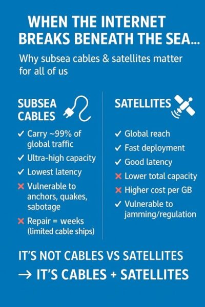
While the debate is often framed as satellites versus subsea, experts increasingly argue for a hybrid approach. The ‘ASEAN: Enhancing Connectivity and Resilience’ 2024 report suggested that a strategic alliance of sea and space could provide the most resilient and inclusive infrastructure model for the Asia Pacific. Subsea cables provide the bulk of capacity and speed, while satellites offer coverage in areas where cables cannot reach.
This synergy is already taking shape. In early 2024, Thailand’s Ministry of Digital Economy announced plans to expand both its LEO satellite coverage and undersea cable landings, citing resilience against climate-related disruptions and cyber threats. Similarly, Australia and Japan have begun exploring cross-value-chain collaboration to diversify their tech dependencies. Governments are increasingly weaving connectivity infrastructure into their national security and digital sovereignty agendas. ASEAN, for instance, is exploring a framework to diversify cable suppliers and reduce over-reliance on any single foreign entity.
China, in particular, has doubled down on its Digital Silk Road, aiming to dominate both terrestrial and orbital networks. From 2022 to 2024, China launched over 400 communication satellites and was involved in more than a dozen subsea cable projects globally, including the PEACE cable that connects Asia to Africa and Europe.
Compared with satellite internet, submarine cables outperform in global connectivity. Cables offer superior bandwidth, lower latency (under 200ms transatlantic), and greater cost efficiency per bit. Satellites, like Starlink, excel in remote coverage and rapid deployment but suffer higher latency, limited capacity, and vulnerability to orbital congestion. While satellites complement cables in underserved areas, they carry only 1-3% of traffic, making hybrid approaches ideal for resilience. Terrestrial fiber optics, often integrated with subsea systems, provide domestic speed but lack intercontinental reach without cables.
_____
_____
Communication in antarctica:
Despite occupying an area larger than Europe and India combined, the Antarctic continent is yet to be reached by one of the ships that lay undersea fibre-optic cables that have helped bring the rest of the world onto a high-speed global telecommunication. Every phone call, every email, every video feed, every byte of data that is exchanged between Antarctica and the rest of the world relies on wireless communications relayed by satellite.
The most robust communications network in Antarctica is probably that of Australia. The Australian Antarctic Division (AAD) has all four of its permanent bases equipped with their own satellite Earth station.
Called ANARESAT, the network provides a 24-hour communications backbone between the Casey, Davis, Macquarie Island and Mawson stations with the AAD’s head office in Kingston, Tasmania. The available bandwidth to Macquarie Island is 256kb/s, while the other three bases enjoy 384kb/s connections.
Unlike typical Earth stations deployed in more benign latitudes, in Antarctica these structures need to be enclosed in a ‘radome’ (radar dome) to protect the dish from the unforgiving conditions. At the four Australian bases, each ANARESAT radome contains a dish measuring 7.3m in diameter. They ‘talk’ in the C-Band to a geostationary Intelsat satellite located over the Pacific Ocean.
The geostationary orbit in which many of the world’s telecommunications satellites are positioned is not that practical for Antarctica. As you get closer and closer to the South Pole, there is a point where – no matter how close to the horizon you manage to point the dish – it is physically impossible to have “line of sight” to a satellite orbiting 36,000km directly above the equator.
Most research stations are lucky in the sense that they are located north of the 82° south where, for practical purposes, beam coverage from geosynchronous satellites ends. In fact, the vast majority of Antarctic stations from most countries are also based north of 82ºS.
_____
_____
Section-9
Undersea communication cable installation:
_
Overall, the process for laying submarine cables typically takes 1 to 3 years, to deliver the system from route planning to an operational asset. Before a cable is laid, a desktop study and careful route survey are conducted, examining water depths, slopes, sediment types, other activities and obstacles. Many cable companies consult with fishermen to identify fishing risks so that potential conflicts may be avoided (or mitigated by cable burial) wherever possible. Pipelines, old cables and material discarded on the bottom must all be located so that the new cable can be laid on the clearest, safest route possible. In cases where a cable must cross a pipeline or existing cable, arrangements are made with the owner of the existing installation to minimise problems.
_
Specialised cableships lay submarine cables by paying them out over the stern. Differential Global Positioning System (DGPS) navigation keeps the ship as close as possible to the planned route. Cable positions are controlled and recorded as precisely as possible to ensure that the designed system length is maintained, that the cable is laid on known ground, and that it can be recovered easily should maintenance be needed later. However, in areas of extreme depth or current, the cable may touch down on the seabed at a distance from the planned route. For this reason, cable owners often recommend that vessel operators give working cables a 1 nautical mile berth. While a ship is laying cable, its speed may vary from stopped up to seven knots. Its manoeuvrability is restricted, and it displays the day signals and lights for a hampered vessel.
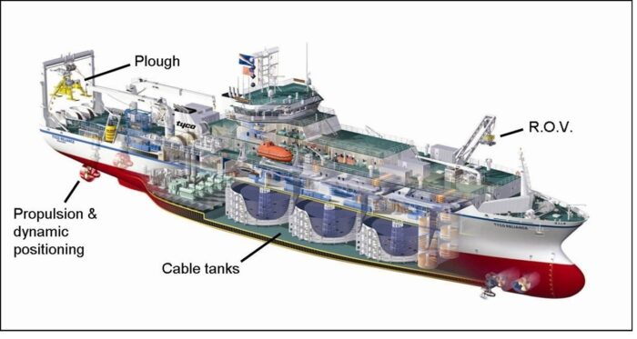
Figure above shows Cableship.
A cable ship is defined as a specialized vessel designed for the installation and maintenance of submarine communication cables, featuring equipment such as cable tanks and braking systems to manage the laying and retrieval of cables in marine environments. Submarine cables are laid on the sea and ocean floor using cable laying ships, which are specially designed seagoing vessels that can be over 500 feet (150 meters) long. These cable laying ships load millions of pounds / thousands of tons of fiber optic cable, by spooling it into large tanks onboard the vessel. Overall, this fiber optic cable spans thousands of miles / kilometers in length. Additionally, cable laying ships typically hold tens to hundreds of repeaters onboard. As an example, Google Cloud’s Topaz submarine cable is being laid by Orange Marine’s cable laying ship named René Descartes. Specifically, the René Descartes ship is carrying 10.2 million pounds (5.1k tons) of fiber optic cable, repeaters, a plough, and a remote operating vehicle (ROV).
_
Installing a submarine transmission cable is a costly and challenging activity. The lifetime of a submarine cable might be tens of years and the technical interventions for its repairing in case of faults are also costly and difficult. Therefore the cable route must be care-fully surveyed and selected in order to minimize the environmental impact and maximize the cable protection.
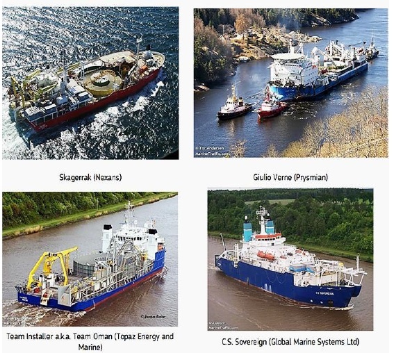
Figure above shows Specialized vessels for cable laying at sea; owner mentioned in the brackets
Laying down the transmission cable on the seafloor is done by specialized vessels. The most active vessels used for such operations are: Skagerrak (owned by Nexans), Giulio Verne (Prysmian), Team Installer (Topaz Energy and Marine) and C.S. Sovereign (Global Marine Systems Ltd). They are all equipped with a turntable for at least 4000 tons of cable and have the appropriate gear to handle it. The ships, which are specialized, are almost all owned by the submarine cable consortium or manufacturers. These ships are stationed at various points along where the cable extends to ensure that in the event of a cable-cut, the ships can set sail immediately for cable repairs.
_
Characteristics of the Modern Submarine Cable Ship:
The modern submarine cable ship is accompanied by the development of submarine optical cable technology. In the late 1980s, the world’s submarine optical cable technology entered a period of rapid development. Compared with the submarine coaxial communication cable, submarine optical cable has undergone a revolutionary change whether in transmission technology or in the process structure, which also proposed higher requirements in the installation of submarine optical cable technology, submarine cable control, and special equipment performance. Compared with the submarine coaxial communication cable, the submarine optical cable needs to have a greater bending radius, longer jointing time, a specialized optical repeater storage stack, and a “branching unit” (BU) installation. These new technologies and installation requirements led the development of submarine cable and its cable working machines towards modernization. In the early 1990s, some of the more modern submarine cable ships started to come into service. AT&T built the cable ships “Global Link” and “Global Sentinel,” and KDD of Japan built the submarine cable ship “KDD Ocean Link.” These are more modern submarine cable ships. Compared with the traditional submarine cable ship, these submarine cable ships retain the bow working mode and the ship stern laying chute, which also have the following salient features: first, due to large tonnage, the load of submarine optical cable and repeater are relatively large; second, the use of an advanced “dynamic positioning (DP) system” has further improved the handling of the submarine cable ship; third, the cable equipment has been able to meet submarine optical cable installation’s technical requirements. From the mid-to-late 1990s to around 2001, with the rapid development and demand of worldwide submarine cable installation, a number of modern submarine cable ships entered the field of submarine optical cable installation. This period was the heyday of the world’s submarine optical cable development, with the global number of submarine cable ships increasing to more than 90. Modern cable-laying ships weigh more than 11,000 tonnes and can lay two to three lines of cable. Cable layers generally do not operate near the coastline or the shores, as it is difficult for them to operate in shallow waters.
Submarine cable-laying equipment:
Modern submarine ships are usually equipped with two types of cable machine: one is the drum-type machine; the other is a linear machine. The two types of cable-laying equipment have different characteristics and uses. The drum-type cable machine, with its diameter usually of 4 m and load capacity of about 25–40 t, is mostly used in operations such as submarine cable grappling and recovery. Its characteristics are a small-occupied space, strong tension, and a steady running capacity. The linear cable machine is mainly used for long-distance submarine cable laying, with a tensile average of about 20 t. Compared with the drum-type cable machine, its characteristics are a larger space occupation and small tension, but it is more suitable for the laying operation of submarine optical cable connecting a repeater or joint box. In order to ensure the laying quality of the submarine cable, repeaters, and joint box, the cable machine in the modern submarine cable ship is usually equipped with “automatic tension control device” and “speed control device” working modes. The operation mode of the automatic tension control device sets certain tension values of the tension meter in advance, according to the requirements of the submarine cable operation design. When the tension on the submarine cable goes over more than the set value, the cable machine automatically pays out or picks up the cable; when the submarine cable tension value is equal to the set value, the cable machine will be automatically stopped. Operation mode of the automatic tension control device is used for cable burial operation, with the working accuracy of 1%. The cable tension meter, in addition, to submarine cable tension testing and calibration on a regular basis, also requires that the ship is tested and verified by professional qualification units and issued a certificate of load test, to ensure that the automatic tension control device has always been in good working condition. The operation mode of the speed control device controls the laying speed, which is also known as the slack control. This kind of work mode is mostly used in submarine cable-laying operation with a working accuracy of 1‰.
__
First, the cables have to be loaded onto a cable-lay vessel that will take them out to sea. Some of these vessels can hold up to 2,000 kilometers of cable on board. It can take 3 to 4 weeks just to load the cable, which can then be laid at a rate of around 200 kilometers per day with the right equipment. Once the cable is on board, starting from shore, the cable is laid out to the edge of the water. The cable laying ship gets as close to shore as possible without grounding, and starts digging. Ships pull a type of plough that digs a trench and lays the cable at the same time. Sometimes, cables have to be picked up if run over another cable, or if the cable can’t be buried. There is a lot of planning that goes into the route the ship will take – undersea mountains, valleys, coral reefs, rocks, and fault lines are all taken into consideration. Preferably, the cables will also be located in areas that minimize the risk of damage from boat anchors and fishing trawlers. To save time in the process, ships can even start from two separate points and lay cable until they meet, then attach the two cables together.
__
Figure below shows part of the 6,600-kilometer (4,000 mile) Marea cable, funded by Microsoft and Facebook, aboard a cable-laying ship.
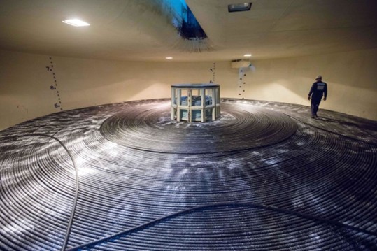
The 6,600-kilometer (4,000 mile) Marea cable weighs over 4.6 million kilograms (10.2 million pounds), or the equivalent of 34 blue whales, according to Microsoft, which co-funded the project with Facebook.
It took more than two years to lay the entire thing.
_
Key Cable Laying Speed Factors:
- Surface Laying: Ships operate around 6 knots in deep, open water.
- Plowing/Burial: When creating a trench for protection, speeds slow to around 1 knot (about 0.3 knots if finding difficult terrain).
- Daily Rate: Specialized vessels can install approximately 100-150 km of cable per day, with some advanced operations reaching 200 km/day.
- Transit Speed: Cable ships travel to the site at 10-12 knots.
- One knot = 1.8 km/hr
- Subsea cable burial speeds typically range from 0.2 km/h (0.1 knots) to over 2 km/h, depending on soil conditions and equipment. Specialized cable ploughs often operate at lower speeds (around 0.2 km/h), while remote-operated vehicles (ROVs) and jet trenchers can achieve higher, more efficient speeds in softer sediments.
_
During deep water installation, a cable may not reach the seabed until the ship is more than 10 nautical miles away. Fishing vessels should keep at least 1 nautical mile away from a cableship displaying these signals, and should never operate gear astern of such a vessel. In areas where bottom fishing and other seabed uses occur, cables are usually armoured and buried in the seabed. The burial depth depends on the types of threats present, the hardness of the sediment, the depth of water, and other factors. In many coastal areas, a burial depth of 0.6 to 1.2 m (2 – 4 feet) is preferred. Where more aggressive fishing gear or anchors are used, cableships sometimes attempt burial depths of several meters, although this makes recovery more difficult if maintenance is needed later. Most cables in depths greater than 1,000 m (550 fathoms) have not been buried. However, in recent years special ploughs have been developed that can bury cables in water depths as great as 1500 m (820 fathoms).
_
Steps involved in installation of submarine communication cables:
- Selection of the provisional path;
- Obtaining permission from the relevant authorities;
- Survey of the path;
- Designing the cable system in order to meet the conditions of the selected path;
- Laying the cable, including burial in appropriate areas;
- A post-lay inspection may be necessary in some cases;
- Notification of cable position to other marine users.
_
The complexity of laying down the cable requires a coordinated work of many specialists in different fields. Path selection is done by power system engineers together with marine specialists. The survey is performed by geologists, geophysicists and oceanographers.
Laying the cable on the seafloor is executed by special structures engineers. The vessel represents just a part of the required gear needed for laying down the cable. It carries the cable and stands for the command centre. But once the cable is in the water other submersible equipment performs the task of settling the cable on its path. For shallow waters divers might be employed to assist the installation while for deep water Remotely Operated Vehicles (ROVs) are manipulated. The work is done with the help of acoustic instruments such as echo-sounders and accurate Global Positioning System (GPS) and differential GPS. The ROVs dig the trench in which the transmission cable is laid, fix the cable on the right route and cover the cable with sediment. Burying the cable in the seabed is a slowly and costly operation but it is paid back by its reliability and extended lifetime.
Cables are buried in the seabed in shallow waters in order to minimize the risks for damages. The trenches in which the cables are placed are dug by a submarine plough and covered by sediment or rocks. When it is not possible to use sediment as a cover, other solutions are applied like using rocks or concrete mattresses as cover or using articulated pipes.
The rate at which the cable is laid-down depends on the type of the cable, the complexity of the cable configuration, the depth and properties of the seafloor (heterogeneous bathymetry and geology). In the case of communication cables a surface laying rate of 100-150 km/day, for new types even 200 km/day, is expectable.
_
An annotated graphic below explains how boats lay undersea cables.
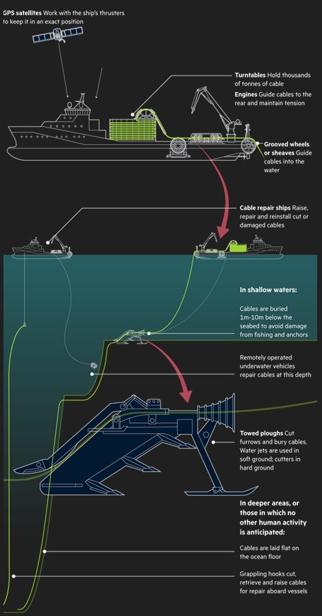
_______
_______
Route selection:
Choosing new cable routes involves a complex process that considers factors such as geographic distance, seabed topography, potential hazards (e.g., fault lines, fishing areas), and regulatory requirements. Thorough surveys are conducted to assess the suitability of the proposed route. A key part of route selection is the identification and understanding of marine geopolitical boundaries that a proposed route may encounter. Access to databases such as Global Maritime Boundaries (NASA, 2009) can prevent unnecessary passage through areas where geopolitical constraints could affect the application or permit to place and maintain a cable on the seabed. Definition of these maritime boundaries is provided by the United Nations Convention on the Law of the Sea (UNCLOS). The extent to which any coastal state controls cable-related activities within its territorial seas and exclusive economic zone varies, and depends on the nature and geographical jurisdiction of federal, state and/or local regulations that enact the provisions of UNCLOS in domestic legislation. For countries that have not ratified UNCLOS, the focus is on existing domestic legislation.
_____
Route survey:
Following the identification of potential cable landings that are to be connected, it is most effective to conduct a full review of pertinent available information in order to define the most efficient and secure route that will then be fully surveyed. This preliminary engineering, commonly referred to as a desktop study (DTS), is generally conducted by marine geologists with cable engineering experience who assemble all available hydrographic and geologic information about the pertinent region, commission fisheries and permitting reports if appropriate, consider the location and history of existing nearby cables and other obstructions, and then design an optimal route to be surveyed. The DTS will also generally include visits to the landings to determine where the cable crosses the beach and links to the cable terminal. Visiting landing sites also provides an opportunity to consult with local officials about possible cable hazards, environmentally sensitive areas, requirements to gain a permit to operate, fisheries, development plans and land access, amongst other factors. A comprehensive DTS will provide an optimal route design that can then be surveyed in the most cost-effective manner.
_
Based on the DTS, an efficient survey can then be designed along an optimized route to fully characterize that route and to avoid hazards and/or environmentally significant zones that may not have been identified from existing information. Surveys include water depth and seabed topography, sediment type and thickness, marine faunal/ floral communities, and potential natural or human-made hazards. Where appropriate, measurements of currents, tides and waves may be needed to evaluate the stability of the seabed, movement of sediment and ocean conditions that may affect cable-laying and maintenance operations.
_
A route survey commonly covers a swath of seabed 1 km wide in water depths down to about 1,500 m, reflecting the need to bury cables for protection according to local conditions. The width of the survey corridor can be adjusted largely in consideration of the expected complexity of the seabed, and the depth to which these complete surveys are conducted will be based on local hazards, particularly bottom trawl fishing and shipping activities, which may require the cable to be buried. Water depth is traditionally measured by echo-sounding, which has now developed into seabed mapping or multibeam systems. Whereas conventional echo-sounders measure a single profile of water depth directly under the ship, multibeam systems provide full depth coverage of a swath of seabed with a width that is three to five times the water depth. Thus, in deep water, a single multibeam track can be up to 20 km wide. As a result, sectors of the seabed are fully covered by a dense network of depth soundings that yield highly accurate images and charts.
_
As multibeam data are collected, side-scan sonar systems may be deployed to produce photographic-like images of the seabed surface. Termed sonographs, the images are used to identify zones of rock, gravel and sand, structures such as sand waves, and human-made objects ranging from shipwrecks to other cables. These images, together with multibeam data and seabed photography, have also been used successfully to map benthic habitats and communities. If cable burial is required, seismic sub-bottom profilers are deployed to measure the type and thickness of sediment below the seabed as well as possible natural hazards. Like echo-sounders, the seismic profilers direct acoustic energy from the ship to the seabed. However, instead of just echoing off the seabed surface, the energy also penetrates through the substrate and reflects off layers of sediment to produce records of their thickness and structure. Sediment coring and other geotechnical testing of the seabed are also generally conducted to help determine its stability and suitability for cable burial.
_
For depths where burial is not required, a single track of a vessel using multibeam bathymetry will generally suffice. The data acquired during such surveys are constantly monitored so that if an unexpected hazard, cable obstruction or benthic community is identified, the surveyors can immediately adjust the planned route and detour around any hazardous or ecologically sensitive areas.
Ultimately, the desktop and field surveys will define a viable cable route and identify the natural and human activities that could impinge on the cable. This information guides the cable design so that it meets the specific conditions of the route.
______
Submarine Cable Installation:
Submarine cable installation, simply speaking, is that the submarine cables on the submarine cable ship are safely put on the designed route in accordance with the installation plan and technical requirements. Due to the differences of water depth, seabed conditions, and protection mode on the designed route, there are often different installation techniques and methods that need to be used. According to the route installation section, it can be divided into the landing installation section (water depth 0–15 m), the burial installation section (water depth 15–1000 m), and the laying installation section (water depth 1000 m above); as seen in figure below.
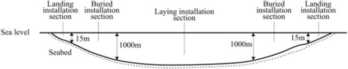
Landing Installation:
Landing installation is when the submarine cables of the cable ship are put onto the beach landing area. The water depth of this section is generally within 0–15 m. The submarine cable landing operation can be divided into three kinds of landing: direct, indirect, and barge.
Burial Installation:
In order to ensure that the submarine cable does not suffer from external damage, it is usually required to bury the submarine cable in a routing section with a water depth of less than 1000 m (some special sections with a water depth up to 1500 m). Submarine cable burial technology has been a continuous development process. In the 1980s and 1990s, the burial depth was up to 1.0–1.5 m, and by the end of the 1990s, the burial technology had a mature capacity of 3 m.
Laying Installation:
Laying installation means that the submarine cable ship conducts the laying of the submarine cable on the seafloor according to design routing and slack control requirements. Laying installation is mainly used for deep-sea areas with a water depth greater than 1000 m, because fishing and other marine development activities in the deep seawaters are fewer, and the probability of damage to the submarine cable by external forces is low. At the same time, the use of laying-installation technology is conducive to reducing the project costs and operational costs.
______
Red buoy markers mark the path of a submarine cable being laid in the ocean as seen in the figure below.
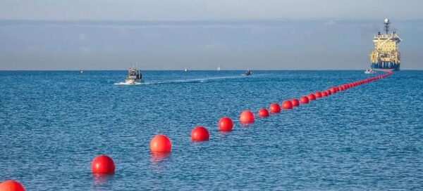
_
Submarine cable laying process starts from the Landing Station, where a long cable section is connected to the landing-point and then extended out to a few kilometers in the sea. This end is connected to the cable on the ship and then the ship starts its cable laying process as seen in figure below.
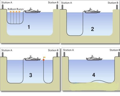
_______
Cable deployment:
As a cable enters the water, its path to the bottom is affected by the marine conditions and any variation in the operations of the laying vessel (Roden et al., 1964). These can be distilled into three key parameters, which are: the ship’s speed over the ground, the speed of the cable as payed out from the cable ship, and water depth (other less important factors are not covered here). Initially, a cable must be payed out slowly, with the vessel moving ‘slow ahead’ until the cable reaches the seabed. This is the touch-down point. Then the ship can increase its laying speed up to a practical maximum of about 11–15 km/hr (6–8 knots), periodically slowing down to pass repeaters or amplifiers through the cable-handling machinery that controls cable tension and pay-out speed. Once a steady state is achieved, the cable pay-out speed should approximate ship’s speed plus 2–3 per cent, assuming the seabed topography is fairly constant. In this steady state, the catenary of the cable will be minimized in the water column. Laying up-slope, however, requires the pay-out speed to be less than the ship’s speed because the water becomes shallower. The opposite is true when laying down-slope, because as water depth increases, more cable is needed to reach the seabed at the engineered touch-down point, assuming the ship’s speed remains constant.
_
Laying operations on a modern vessel undergo constant and accurate monitoring. The ship’s position and speed over the ground are measured by the satellite-based differential global positioning system, and the water depth by precision echo-sounders and seabed mapping systems, whereas cable pay-out speed and length are recorded by a rotameter. Onboard, the cable engineer scrutinizes laying progress with constant reference to the engineered route plan, making adjustments if necessary. In addition, there may be computerized tracking of the entire laying operation that includes detection of external factors such as winds and ocean currents, plus the means to correct for such influences. Once laid, the cable comes ashore and is connected to the terminal or cable station, which assumes full management of the telecommunications system.
_
Cables that extend across the continental shelf (typically 0–130 m deep) to a depth range of 1,000–1,500 m, are commonly buried below the seabed to protect them from damage by other seabed users. The most effective method of burial is by sea plough. As a cable approaches the seabed, it is fed through the plough, which inserts the cable into a narrow furrow. Different plough designs are available to suit various bottom conditions, e.g. the traditional plough-share is well suited for muddy substrates, whereas sandy sediments may require a plough equipped with a water jet to cut a trench into which the cable is placed.
Below a depth range of 1,000–1,500 m, cables are deployed mainly on the seabed, although in rare instances burial may extend into deeper water. This depth limit is presently the extent of modern bottom trawlers, but their forays into deeper water may necessitate burial in even greater water depths.
Typically, cable size and weight decrease with depth as the requirement for protective armour diminishes to zero. Such lightweight cables are easier to handle than armoured varieties, but cable slack must still be controlled carefully so that the cable follows the seabed contours. This may involve engineering 2–3 per cent slack into the laying procedure.
_
The process of laying undersea cables is a highly coordinated and technical operation that requires careful planning, precise installation techniques, and ongoing monitoring. By following these steps, cable ships ensure that vital communication links are established and maintained, allowing the global transmission of data across oceans. From surveying and planning to installation and testing, the journey of laying undersea cables showcases the remarkable engineering that supports our connected world.
Besides the use of high quality fiber, the links include solid state optical repeaters, integrated to the cables at intervals of about 100 km. They relay the degraded signal, allowing links to be extended for thousands of miles. These repeaters are powered by energy that is transmitted through the cable itself, making ground stations are really necessary only at the points where you need to perform packet routing or integrating multiple links.
These cables are installed on the ocean floor at a cost of millions of dollars with specialized vessels. The work is done in two stages, with the ship moving slowly and dumping the cable on the seabed and connected to a robotic installer digging a shallow grave on the ocean floor and burying the cable at the same speed as seen in the figure below. For signal degradation, the cable needs to be installed perfectly straight, which demands a particularly precise navigation.
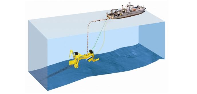
_
Fiber is laid on the ocean floor using special ships and underwater robotic units. The ship moves slowly along a pre-planned route, lowering the cable to the ocean floor and skirting all the underwater mountains and hollows. Sometimes this happens at depths of up to 8,000 meters, where the pressure is such that it would squeeze a tank. Although the process is cumbersome, the cable is laid with jewel-like precision. Even a slight deviation from the route can cause damage if, for example, it is stretched too tightly on an underwater slope.
An average of 10-12 kilometers of fiber is buried and laid per day. This is done by using underwater plows as well as robots that remove debris or rocks from the cable’s path. Deeper waters are left uncovered, while closer to shore the cable is protected — it is a favorite of ship anchors and fishing trawlers. Cable ships use “plows” that are suspended under the vessel. These plows use jets of high-pressure water to bury cable three feet (0.91 m) under the sea floor, which prevents fishing vessels from snagging cables as thrall their nets.
Ships are limited to a speed of eight knots (15 km/h) while laying cable to ensure the cable lies on the sea floor properly and to compensate for any small adjustments in course that might affect the cables’ position, which must be carefully mapped so that they can be found again if they need to be repaired.
_______
Cable recovery:
Cables are retrieved from the seabed for repairs, replacement or removal (Alcatel-Lucent, 2008). Recovery may result from damage by human activities or natural events, failure of components, cable age (design life is typically 20–25 years), or a need to clear congested routes. Recovery generally entails:
- location of the cable and, if a repair is required, identification of the faulted section;
- retrieval of the cable with specially designed grapnels deployed from the repair vessel;
- lifting to the surface for removal or repair.
During the haul-up process – sometimes from 1–3 m below the seabed – the strain on the cable is substantial. Thus recovery, like laying, is a complex process that takes into account a wide range of variables:
- the speed and angle of recovery;
- the ship’s track along the cable route;
- the drag of the cable, which may have increased due to biological growth on the cable’s exterior;
- water depth, current velocity, wave effects on vessel motion, and any natural or human-made objects, such as ship wrecks, that could potentially snag the ascending cable.
To aid this difficult process, manufacturers provide recovery tension tables that describe the maximum recommended recovery speed in a given water depth and at a given recovery angle for each cable type manufactured.
______
______
Section-10
Vulnerability of subsea internet cables:
Underwater cables keep the internet online. When they congregate in one place, things get tricky. The Asia-Africa-Europe-1 internet cable travels 15,500 miles along the seafloor, connecting Hong Kong to Marseille, France. As it snakes through the South China Sea and toward Europe, the cable helps provide internet connections to more than a dozen countries, from India to Greece. When the cable was cut on June 7, 2022, millions of people were plunged offline and faced temporary internet blackouts. The cable, also known as AAE-1, was severed where it briefly passes across land through Egypt. It affected about seven countries and a number of over-the-top services. The worst was Ethiopia, that lost 90 percent of its connectivity, and Somalia thereafter also 85 percent. While connectivity was restored in a few hours, the disruption highlights the fragility of the world’s 550-plus subsea internet cables, plus the outsized role Egypt and the nearby Red Sea have in the internet’s infrastructure. The global network of underwater cables forms a large part of the internet’s backbone, carrying the majority of data around the world and eventually linking up to the networks that power cell towers and Wi-Fi connections. Subsea cables connect New York to London and Australia to Los Angeles.
_
Sixteen of these submarine cables—which are often no thicker than a hosepipe and are vulnerable to damage from ships’ anchors and earthquakes—pass 1,200 miles through the Red Sea before they hop over land in Egypt and get to the Mediterranean Sea, connecting Europe to Asia. The last two decades have seen the route emerge as one of the world’s largest internet chokepoints and, arguably, the internet’s most vulnerable place on Earth. Where there are chokepoints, there are single points of failure. Because it’s a site of intense concentration of global movement, that does make it more vulnerable than many places around the world. The area has also recently gained attention from the European Parliament, which in a report highlighted it as a risk for widespread internet disruption. “The most vital bottleneck for the EU concerns the passage between the Indian Ocean and the Mediterranean via the Red Sea because the core connectivity to Asia runs via this route,” the report says, flagging extremism and maritime terrorism are risks in the area.
_
Undersea cables can be highly vulnerable to a variety of factors. Most cable damage is unintentional, mainly stemming from accidental human interaction with the cables. Still, potential hazards to the cables range from anchoring and fishing equipment to extreme weather such as earthquakes and landslides. Damage to submarine cables is relatively common—an estimated 150 to 200 cables are severed each year—mostly from fishing equipment or anchors. The scale and exposure of undersea infrastructure also make it an easy target for saboteurs operating in the grey zone of “deniable attacks short of war.” In 2023, Taiwanese authorities accused two Chinese vessels in the area of cutting the only two submarine cables that supply internet to Taiwan’s Matsu Islands, plunging its 14,000 residents into digital isolation for six weeks. Although there was no clear confirmation of a deliberate attack, Taiwan’s ruling Democratic Progressive Party (DPP) pointed to a remarkable frequency of Chinese vessels causing cable disruptions—27 times since 2018—and accused Beijing of harassing Taiwan in a classic case of “grey-zone aggression.” Similarly, in October 2023, a Baltic Sea telecom cable connecting Sweden and Estonia sustained damage at the same time as a Finnish-Estonian gas pipeline and cable. Carl-Oskar Bohlin, Sweden’s minister for civil defense, said the Swedish-Estonian cable was damaged as a result of “external force or tampering” and that Estonian officials had concluded that the three incidents were “related.” An investigation focused on a Russian-flagged ship and a Chinese-owned vessel operating in the area as the likely sources of the alleged sabotage. Private cable firms have also identified the South China Sea and the Red Sea as two notable choke points in the international undersea cable network. In the Red Sea, a spate of Houthi attacks has indirectly damaged cables in this major artery connecting Europe and Asia.
_
A single submarine cable is anywhere from 0.75 to 2.5 inches thick. The armored cables closer to shore can have up to two layers of galvanized wires protecting the fiber optic core. These aren’t the kind of cables you cut with a pair of wire cutters. The idea that saboteurs in wetsuits would dive to the bottom of the Mediterranean Sea and cut a fiber optic cable, though not impossible, is highly unlikely, if only because doing so would be a good way to wind up dead. These cables are carrying thousands of volts of power. Attempting to cut such a line could easily kill you, making sabotage “pretty unusual and pretty dangerous.”
_
Less likely, but still of concern, geopolitical rivals such as China could potentially collect the data flowing through this infrastructure. U.S. officials have sounded the alarm over the involvement of Chinese firms in new global seabed cable projects, suggesting that China could monitor data running through the cables or even sever entire countries from the internet either through software or interfering at coastal landing stations for the cables. As concerns grow over Chinese delays with granting permits, challenges facing cable repair, and even the potential of state tampering with cables, U.S. and allied-country companies have rerouted planned subsea cable systems away from landing in Chinese territories and other vulnerable areas.
The overreliance on Chinese repair ships due to limited alternatives in the marketplace is another vulnerability if, during a time of military conflict, the Chinese government prohibits access to its repair ships and subsea cables are left damaged without timely repair. There are concerns that Chinese cable repair companies such as SBSS could tap undersea data streams, map the ocean floor to conduct reconnaissance on U.S. military communication links, or obtain highly specific location data from the internal documentation of cable systems that would allow belligerent parties to cut cables with speed and precision.
_
While the international focus in this theater has largely been on the competition between the United States and China, Russian threats to subsea infrastructure are their own significant concern. Russia relies significantly less on subsea cables than either the United States or China due to its position as a continental power with internet connectivity to Europe and Central Asia and less of a focus on international trade. This makes Russia less vulnerable to disruptions in subsea cable infrastructure and potentially more willing to exploit these vulnerabilities in other nations. The strategic importance of undersea cables has not been lost on Russia, which views this infrastructure as a critical point of leverage against the security of Western nations.
_____
_____
Undersea cables, carrying over 95% of global internet traffic, are highly vulnerable to physical, environmental, and malicious threats, with 150-200+ faults occurring annually. Key technical vulnerabilities include accidental damage from fishing/anchors (70%+ of faults), seismic activity, strategic, concentrated bottlenecks at shallow landing stations, and targeted sabotage or wiretapping, frequently exacerbated by limited global repair capacity.
Figure below shows causes of faults of submarine cables (%).
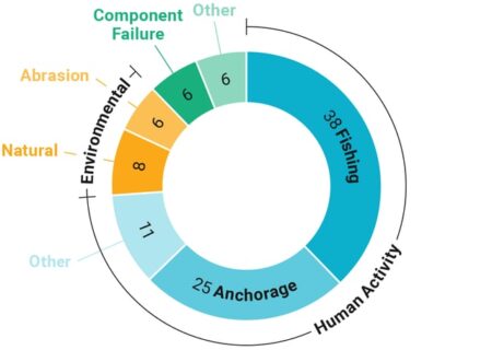
_
Primary Technical Vulnerabilities:
- Physical Damage & Human Activity: The vast majority of cable faults are unintentional, caused by fishing vessels (bottom trawling) and ship anchors in shallow waters.
- Subsea Choke Points: Concentration of numerous cables at specific coastal landing points creates high-impact failure points, where one incident can disrupt entire regional networks.
- Environmental & Natural Hazards: Earthquakes, submarine landslides, and volcanic activity pose significant risks, especially where cables cross tectonic boundaries.
- Targeted Sabotage & Subversion: Their known, mapped locations make them easy targets for malicious actors seeking to disrupt data flow or sabotage infrastructure.
- Surveillance and Data Interception: Sophisticated actors can tap into cables at the sea floor or at landing stations to siphon data, posing major espionage risks.
- Repair Limitations: The limited global supply of specialized repair ships and lengthy, complex permitting processes for repairs lead to long downtimes.
______
______
Nature of the Threat:
Undersea cables have two types of vulnerabilities: physical and digital. However, it should be noted that the most common threat today—responsible for roughly 150 to 200 subsea cable faults every year—is accidental physical damage from commercial fishing and shipping, or even from underwater earthquakes. Industry actors have the prime responsibility for accounting for and mitigating these incidents. Of greater concern are more malicious threats. Regarding physical challenges, the two primary concerns are that the cables might be destroyed or tapped—by either a non-state actor, as per some recent isolated incidents of piracy, or, more likely, by a state adversary like Russia. Moscow has two primary means by which it could directly threaten the cables: submarines and surface vessels that can deploy autonomous or manned submersibles.
There are several conceivable objectives severing a cable might achieve: cutting off military or government communications in the early stages of a conflict, eliminating internet access for a targeted population, sabotaging an economic competitor, or causing economic disruption for geopolitical purposes. Actors could also pursue several or all of these objectives simultaneously.
_
More difficult and subtle than destroying the cables is tapping them to record, copy, and steal data, which would be later collected and analyzed for espionage. It is believed this could be done in one of three ways: inserting backdoors during the cable manufacturing process, targeting onshore landing stations and facilities linking cables to networks on land, or tapping the cables at sea. Each is more difficult than the one before, and the last—tapping the cables at sea— is believed to be so technically challenging that it is not publicly known whether any country is even capable of it. The most vulnerable point of submarine cables is where they reach land: the landing stations.
_
The final type of threat is cyber or network attacks. By hacking into the network management systems that private companies use to manage data traffic passing through the cables, malicious actors could disrupt data flows. A “nightmare scenario” would involve a hacker gaining control, or administrative rights, of a network management system. At that point, they could discover physical vulnerabilities, disrupt or divert data traffic, or even execute a “kill click” deleting the wavelengths used to transmit data. The potential for sabotage or espionage is quite clear—and according to Lawfare, the security of many of the network management systems is not up to date. The recent SolarWinds and Colonial Pipeline cyberattacks also exposed the cyber vulnerabilities of the U.S. private sector with dramatic implications for national security.
______
______
Risk Factors for Submarine Cable Systems:
Three primary factors –– lack of redundancy, lack of diversity of cable routes, and limited repair capacity –– very likely raise the likelihood of severe outages caused by damage to submarine cables. Additionally, permitting issues stemming from different regulatory environments and geopolitical tensions can extend the timeline for cable repairs, as can kinetic conflicts in the vicinity of cable breaks.
-1. Lack of Redundancy:
Jurisdictions with limited alternate options to reroute traffic are most vulnerable to prolonged or significant disruptions. Following the May 2024 damages to SEACOM and EASSy, Kenya rerouted traffic to the TEAMS cable, with Safaricom and Airtel reporting they had activated alternative connectivity, but Tanzania experienced greater disruption due to its fewer connectivity options. In this case, the earlier February 2024 Red Sea damages further limited alternate options for connectivity, with Microsoft stating that the two incidents together “had reduced the total network capacity for most of Africa’s regions.” By contrast, Cloudflare reported that two cable cuts in November 2024 in the Baltic Sea –– the BCS East-West Interlink connecting Sweden and Lithuania, and the C-Lion1 cable connecting Finland and Germany –– “resulted in little-to-no observable impact to the affected countries … in large part because of the significant redundancy and resilience of Internet infrastructure in Europe.” Highlighting the importance of redundancy measures, the European Commission reported in 2024 that “many islands in the Union, including the three island Member States [Cyprus, Ireland, and Malta], as well as the EU outermost regions and overseas countries and territories, are almost entirely dependent on such submarine cables for intra-Union communications,” indicating a likely higher level of vulnerability.
_
While satellites provide edge connectivity and connect locations that do not have easy access to physical infrastructure, they account for a small amount of overall global capacity and typically cannot replace fiber-optic submarine cables, which also move large amounts of data faster and more cheaply. TeleGeography reports that “cables can carry far more data at far less cost than satellites,” and only a small percentage of intercontinental data traffic is transmitted via satellite, according to Cloudflare. For example, the US Federal Communications Commission (FCC) reports that satellites account for just 0.37% of all US international capacity. According to the ICPC, “a trans-pacific fibre-optic call need only travel about 5,000 miles point-to-point,” compared to a satellite call, which must travel 22,235 miles from the Earth to a satellite and then another 22,235 back. Illustrating this, a backup microwave system was activated following damages to two submarine cables connecting Taiwan and the Matsu Islands in February 2023, but only restored an estimated 5% of the bandwidth that the cables had provided, with full internet access not restored until April 2023.
__
-2. Lack of Diversity of Cable Routes:
Deploying submarine cables along similar geographic routes very likely increases systemic risk by creating single points of failure. Countries with multiple submarine cables routed along varying geographic routes are more insulated from major connectivity losses; conversely, those with fewer connecting cables, placed in close proximity to each other, are almost certainly more susceptible to multiple cable damages and associated disruptions. Recent incidents of damage to multiple cables at once indicate that threat actors could attempt to exploit the concentration of cables along similar routes in an effort to cause prolonged outages across a geographic area. For example, the Red Sea cable cuts in February 2024 illustrated the importance of route diversity. The March 2024 damages to four cables off West Africa, which all occurred due to an underwater landslide in the “Le Trou Sans Fond” canyon off of Côte d’Ivoire, illustrated how a concentration of cables at one point can make multiple cables susceptible to human-made threats or, as in this case, natural phenomena. Similarly, Egypt is a critical internet chokepoint through which multiple submarine cables connecting Europe, Africa, and Asia run; the vulnerabilities associated with this arrangement were apparent following June 2022 damages to both the AAE-1 and the SeaMeWe-5 cables.
_
The concentration of submarine cables at a single cable landing station increases the likelihood that damage to or near a landing site will impact multiple cables. These stations provide multiple functions, including supplying power to the cable and connecting it to terrestrial networks, and their locations are often chosen based on access to existing infrastructure or regulatory factors, rather than because they offer particularly high protection from natural disasters or physical threats, such as sabotage or surveillance. As a result, cables frequently cluster around or at the same landing site –– raising the threat that sabotage or espionage operations could impact multiple cables at once by targeting landing stations. For example, according to the US FCC, landing sites on the southeastern US coast are clustered in three primary locations in Florida, with nearly all landing sites developed to support multiple submarine cables. In October 2022, cybersecurity company Zscaler warned that cuts to multiple cables at landing stations in Marseille linking the city to Milan, Barcelona, and Lyon “impacted major cables with connectivity to Asia, Europe, US and potentially other parts of the world.” In August 2023, the European Union Agency for Cybersecurity (ENISA) reported that landing stations represent a weak point in the ecosystem due to their vulnerability to “espionage attacks, deliberate power cuts, sabotage attacks with explosives, or even missile attacks in the case of a military conflict.”
_
-3. Limited Repair Capacity Poses Long-Term Problem:
Repair capacity, which continues to lag behind the expansion of submarine cable networks, almost certainly represents an underappreciated point of vulnerability in the submarine cable ecosystem. As cable systems have expanded dramatically, investment in ships that can service these cables has lagged behind, resulting in the growth of cable systems outpacing repair capacity. Most of these vessels are therefore focused on laying new cable systems, constraining their ability to respond immediately to cable faults. According to ENISA, given the complex nature of repairs and limited repair capacity, “a coordinated attack against multiple subsea cables could have a major impact on global internet connectivity.” For example, the Léon Thévenin, a cable repair ship docked in Cape Town, South Africa, was the only vessel dedicated to serving Africa at the time of the March 2024 cable outages, extending the repair timeline. In February 2023, all five of Vietnam’s operational undersea cables suffered partial or total damage at the same time, resulting in the loss of 75% of its data transmission capacity. With nearby ships busy, repairs on all cables were not fully completed until late November 2023, and telecommunications firms were forced to purchase spare terrestrial capacity to help stabilize connections. Reflecting concerns regarding the limited availability of repair vessels, the US established the Cable Security Fleet in 2020 with two dedicated US-flagged cable repair ships (the CS Dependable and CS Decisive) to speed repairs to submarine cables relevant to US national security.
_
Unless significant investments are made in streamlining repair processes and expanding cable ship repair capacity, repair times are likely to continue trending upward. According to SubTel Forum, the average repair time for the restoration of cable faults has risen from 2015 to 2024, with the average repair time in 2023 consisting of 40 days. Vietnam’s five submarine cable systems, which account for most of its international bandwidth, experience an average of fifteen incidents annually; prior to 2022, repairs lasted one to two months per incident, but have recently lasted longer, extending disruptions. This is almost certainly a result of the increasing gap in the rates of subsea cable infrastructure expansion and stagnating repair capabilities.
_
Regulatory Factors, Conflict, and Territorial Disputes Likely to Prolong Repair Timelines:
Regulatory hurdles, such as complex and lengthy permitting processes for repair ships that vary by national territory, likely prolong repair timelines, exacerbating the impact of limited repair capacity. Cable damage in areas subject to territorial disputes and ongoing kinetic conflicts almost certainly increases the prospect of prolonged outages due to the denial of access to repair vessels. The International Institute for Strategic Studies reports that repairs in the Asia-Pacific region take up to 30 days on average from notification of an incident, compared to fifteen in North America, due to more stringent permitting requirements. For example, repairs to April 2024 damages to the SeaMeWe-5 cable in Indonesian waters, which reduced Bangladesh’s internet capacity by a third, were not completed until June 28, 2024, as Jakarta’s cabotage policy delayed repairs for several weeks. In March 2024, telecommunications provider SEACOM reported that it would likely take longer than expected to repair three cables in the Red Sea damaged by a ship hit by Houthi strikes since permitting could take up to eight weeks to obtain. The Yemeni government refused to grant permission to initiate repairs of the damaged AAE-1 cable to the cable’s operating consortium, which includes telecommunications firm TeleYemen, as one of the firm’s two branches is under the control of the Houthi group. An investigation of the consortium reportedly delayed repairs of the AAE-1 until July 2024. Further, SubTel Forum reported that ongoing threats posed by the Houthi group likely limited companies that agreed to carry out repairs and incurred high premiums.
Additionally, amid ongoing territorial disputes between China and the Philippines in the South China Sea, the China Coast Guard (the CCG) has attempted to block Philippine resupply operations to vessels at the Second Thomas Shoal, Scarborough Shoal, and Sabina Shoal. In addition to harassing Philippine vessels, the CCG and other Chinese forces have for decades interfered with vessels from other claimants in the South China Sea, as well as vessels operated by outside powers like the United States. These incidents suggest that Beijing could take similar action to block repair vessels from accessing damaged submarine infrastructure in the event of a potential escalation of tension or outbreak of hostilities around Taiwan.
______
______
Strategic recommendations to reduce subsea cable vulnerability:
Immediate Policy Interventions:
-1. Streamline Regulatory Processes:
-2. Classify Submarine Cables as Critical Infrastructure:
-3. Incentivize Investment:
Medium-Term Strategic Initiatives:
-1. Develop Domestic Repair Capabilities:
-2. Establish Cable Protection Zones:
-3. Enhance International Partnerships:
Long-Term Strategic Vision:
-1. Diversify Landing Stations:
-2. Establish Regional Hubs:
-3. Create a National Critical Information Infrastructure Protection Centre:
________
________
Section-11
Cable fault:
An undersea internet cable fault is a physical breach, break, or malfunction in a subsea communication cable, typically caused by fishing activities, ship anchors, or natural disasters, disrupting international data transmission. These faults are common, occurring roughly 150–200 times per year, and cause internet outages or slowdowns for users. Subsea cables are the backbone of global connectivity, and these undersea networks are essential for internet access, international communications, and energy transmission. Despite their importance, subsea cables face numerous challenges. They are susceptible to physical damage from fishing activities, anchoring, and natural disasters such as earthquakes and underwater landslides. Additionally, the cables are vulnerable to deliberate sabotage, as evidenced by recent incidents in the Baltic Sea where suspected sabotage disrupted power and communication lines. Repairing these cables is a complex and costly endeavour, often requiring specialized ships and equipment, leading to prolonged downtimes and significant financial losses. End users hardly notice those faults because the data traffic is usually rerouted through alternative cable paths. Total internet outages only occur when there is no broadband redundancy available.
_
Cable damage comes in many forms. When damage is severe enough to affect transmission, it is considered a fault. Submarine communication cable faults are primarily caused by human activity (anchors, fishing) and natural hazards (landslides, currents), resulting in severe, electrical, or structural damage. Major fault types include shunt faults (insulation failure/short circuits), broken conductors (open circuits), sheath faults (water ingress), and complex breaks requiring seabed repairs.
One type of fault is a complete break, when a cable is pulled apart or severed. In such a case, the damage obviously affects both the optical fibres carrying communications and the copper conductor carrying the electrical current required to power the signal-boosting repeaters used on long-haul cable systems.
The modern submarine telecommunications cable has an outside diameter of 17–50 mm, depending on the type of cable and armour. The breaking strength of such cables ranges from a few tonnes to more than 40 tonnes for the double-armoured types. However, a cable may be rendered inoperable by forces smaller than those needed to sever it.
If a hard object in contact with a cable penetrates the armour and insulation to expose the copper conductor that carries electrical current, the usual result is that electrical current flows to the sea to form a shunt fault. In this case, the optical fibres may remain intact and capable of carrying signals, but the repeaters beyond the shunt may lack power and the cable may stop working. Sometimes, the voltage of the electrical power feed equipment at the ends of the cable can be balanced so that the repeaters on each side of the shunt continue to function, and the cable remains in service for a short time until a repair ship arrives. Shunt faults can result from fishing gear striking a cable or abrasion on the seabed, amongst a number of causes. In other cases, such as crushing, bending or pulling, the optical fibres themselves may be damaged. An optical fault results in loss of communication on one or more fibres. When a fishing trawl, anchor or other equipment snags or hooks a cable, it may exert enough force to pull the cable apart. Whatever the cause of the fault, it normally triggers an immediate alarm in the monitoring equipment, which runs constantly in the terminal stations on shore.
_
The most common threats to the undersea network include:
- Fishing trawlers: Nets and dredges dragged along the seabed are the leading cause of cable damage.
- Ship anchors: A carelessly dropped anchor in a busy shipping lane can easily sever a cable, cutting off a country’s primary data link.
- Natural disasters: Underwater earthquakes and landslides can snap cables, as seen in the 2006 Hengchun earthquake, which temporarily crippled internet access across much of Asia.
- Geopolitical sabotage: In an era of increasing global tensions, the strategic vulnerability of these cables to deliberate sabotage is a growing concern for national security agencies.
Fortunately, the network is designed with redundancy in mind. Data traffic can be quickly rerouted through alternative cables if one is damaged, which is why a single cable cut rarely leads to a total internet blackout for an entire region.
_
Threat from fishing:
On a global scale, the number one cause of submarine cable faults is believed to be fishing with mobile gear such as bottom trawls, beam trawls and dredges. A few types of static (fixed) gear such as longlines, gillnets, and FADs (Fish Aggregating Devices) have also caused faults. When fishing gear such as stow nets use large anchors, such fishing anchors can present extreme risks to cables. Sometimes it is not the fishing gear itself which causes the problem, but the grapnels which fishermen use to recover lost gear.
The overall threat from fishing activity derives from a combination of the seabed penefration of each method, the power of the vessels involved and the areas over which they operate. Of the methods currently in use, trawling is considered the greatest threat to cables, although bottom set fixed fishing gear and dredges also pose a significant risk.
A significant portion of commercial fishing activity relies on trawling, that involves towing a fishing net (“trawl”) behind a boat. Trawlers can drag their trawls within the water column (pelagic trawling) or over the seabed (bottom trawling). In the latter case, damage to cables or pipelines can occur from pulling fishing gear over them, or from fishing gear getting stuck underneath. This can cause cables or pipelines to be moved or dragged along, in the worst case leading to breakages.
Whilst cable burial to a target depth of 0.6 to 1 metre into the seabed in water depths down to 1000 metres has resulted in a substantial reduction in the number of fishing related cable incidents on new systems, the increasing demand for fish and shellfish throughout the world shows that fishing methods capable of damaging cable are spreading to deeper waters as more traditional fisheries decline and new resources are exploited.
Threats from anchors:
Anchors being dropped directly onto a cable or pipeline can also cause localized damage. The anchors of commercial vessels can penetrate the seabed to a depth of almost one meter, and can therefore hook a cable, even if it’s silted in. Further damage can occur if the anchor is moved and hooks the cable or pipeline. This issue is not specific to fishing vessels but for vessels generally. Anchors are used for a wide variety of tasks ranging from the positioning of fishing gear through to the mooring of large merchant ships and the permanent fixture of offshore platforms used in the oil industry. We have even encountered a fault caused by a meteorological buoy dragging its anchor, although such events are rare. Statistics do indicate that the threat from anchors diminishes sharply with water depth to around 150 metres, beyond which anchor faults are virtually unknown.
_
It is helpful to form categories to differentiate between the various fault scenarios. Roughly speaking, there are three causes of faults: natural, human, and external as seen in figure below.
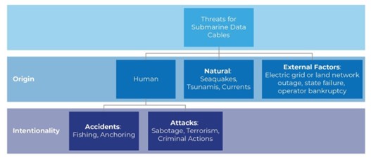
Natural causes:
First, cable rupture can be the outcome of natural disasters like seaquakes and other seismic activity, tsunamis, and underwater currents during storms. Further natural factors are long-term processes that may lead to abrasion of the protective layers of cables, such as corrosion, tide, and weather-related currents. Natural impacts account for about one-fifth of cable incidents. These kinds of cable damages are less likely than human-caused, accidental cable breaks. However, they bear the potential of multiple simultaneous failures. For example, in the aftermath of the Tōhoku earthquake of 2011, four of 20 submarine cables to Japan ruptured. These simultaneous outages seriously impacted inter-Asian and transpacific internet traffic. In this case, the loss of bandwidth could be compensated with Japan’s remaining cables. For territories with fewer redundancies, parallel breaks have a higher probability of complete internet blackout.
Human causes:
Human-caused damages to submarine cables are either intentional or unintentional. The majority of accidents occur as a consequence of everyday maritime activities, with fishing, anchoring, and dredging most frequently the cause of damage. Of such, mainly unintended cable damages by commercial marine activity amount on average to more than 70 % of the yearly incidents. This large share can be explained by unintended accidents rooted in unfamiliarity with legal rules and protection zones or negligent behaviour and deliberate risk-taking when operating near cable installations.
External factors:
The final category of submarine cable dysfunctions is related to the external infrastructures and necessary services they depend on. First, fibre-optic data cables longer than 150 km require electric power to function because repeaters need to compensate for signal losses over distance. As a rule, the electricity can be supplied from each landing station of a cable, making a data cable power outage scenario less probable. However, extensive power outages that affect both cable landing stations result in loss of connectivity. Second, the loss of land-based regional communication infrastructures (cables, data centres, IXP), whether for physical (destruction) or non-physical (censorship, routing failures) reasons, renders international submarine cables useless. Another factor that is often overlooked is the roles of cable operators. If security for the cable operating enterprises and their personnel cannot be provided, lack of maintenance threatens the function of a submarine cable in the long term. The same consequence is probable for cases of bankruptcy of cable operating enterprises.
________
________
Threats to Undersea Telecommunication Cables:
Given the heavy reliance on undersea telecommunication cables for consumer, businesses, and government communications, including some military communications, some U.S. officials, industry stakeholders, and scholars have cited the need to protect them from damage. The following paragraphs summarize some of the threats posed to undersea telecommunication cables.
Unintentional Damage to Cables:
Unintentional damage to undersea telecommunications cables can be caused by human activities such as anchoring (most commonly related to shipping) and commercial fishing; natural hazards such as submarine landslides, volcanos, earthquakes, tsunamis, and strong waves and currents; and animal threats (e.g., sharks or barracuda that may bite cables), although rare.
Figure below presents International Cable Protection Committee (ICPC) data on the causes of cable faults, based on analysis of fault data from 1959 to 2021.
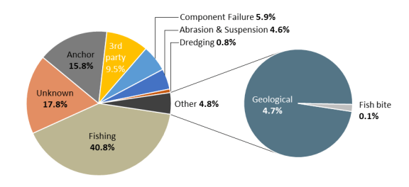
Between 65 and 75 per cent of all fibre-optic cable faults occur in water depths shallower than 200 m, and result mainly from fishing and shipping activities. By comparison, failures caused by natural hazards make up less than 10 per cent of all faults and 6% by equipment failure.
Human Activities:
The ICPC, a non-profit organization formed in 1958 to promote the protection of international undersea telecommunications and power cables, estimates that human activities—fishing, anchoring, and dredging, among others—accounted for roughly two-thirds of undersea cable faults globally between 1959 and 2021. ODNI, in its 2017 report, Threats to Undersea Cable Communications, stated that the majority of threats to cables are accidental incidents involving humans. For example, a submarine telecommunication cable was accidentally severed by a ship off the coast of Somalia in 2017, leading to a three-week internet outage costing the country $10 million a day according to a Somali government official.
Natural Disasters:
Although undersea telecommunication cables are infrequently damaged by natural disasters (e.g., earthquakes, tsunamis), the impacts of such incidents may be severe and long-lasting. For example, on January 15, 2022, a volcanic eruption and earthquake severed Tonga’s only internet connection—an undersea telecommunication cable that connects it to Fiji and other international networks—which took five weeks to fully restore. During the outage mobile network providers offered some connectivity to customers on the main island (where most of the population lives) using satellite connections, although customers reported that capacity was limited, affecting their ability to communicate, connect to the internet, and conduct financial transactions. While repair ships replaced the 56 miles of the international cable connecting Tonga to Fiji (and the rest of the world), the domestic cable, connecting Tonga to its outer islands and the outer islands to each other, was still under repair. In March 2022, Tonga Cable Ltd., Tonga’s state-owned cable owner, stated the repairs could take up to a year.
_
Intentional Damage to Undersea Telecommunication Cables:
Intentional acts of damage to cables occur, but are rare, according to TeleGeography. While some intentional incidents (e.g., cutting of cables, vandalism) are publicly reported, the actual number of incidents globally or in the United States is unknown.
Intentional damage to undersea telecommunication cable systems may include physical damage to cables, such as cutting cables at sea or on land, or attacking cable landing stations. In 2022, two separate attacks on undersea telecommunication cables in France consisted of individuals cutting cables after breaking into cement casings at several cable landing sites; these attacks were described as “coordinated” and “unprecedented” in scale by telecommunication industry representatives. The cable cuts disrupted communications in several parts of France, and slowed traffic globally.
In the 2017 AEP Cable Threats Report, the AEP Team notes that there have been limited reports of underwater attacks on cables because they are difficult to access on the sea floor. Instead, “landing stations are the most accessible and impact-rich targets as they are concentrated in a handful of coastal locations.” Intentional damage to terrestrial portions of heavily used undersea telecommunication networks is therefore an area of potentially greater risk. For example, in November 2022, a dual cut to the terrestrial portion of the South East Asia–Middle East–Western Europe 5 cable in Egypt disrupted internet services in multiple countries. Companies that track network traffic reported traffic dropping in countries in East Africa, the Middle East, and South Asia, and regional impacts to cloud service companies, including Google, Amazon, and Microsoft Cloud.
Risks to subsea cables also may be greater if foreign nations are involved. In 2018, the Associated Press cited a Russian publication stating that Russia has the capability to cut cables, connect to top-secret cables, and jam underwater sensors that detect intrusions. The larger the extent of the military purpose of a submarine cable, the higher its probability is to be targeted in a conflict. For example, submarine cables connecting naval bases and satellite receiving stations are characterised by a larger share of military use, making them reasonable targets.
Bad actors may also leverage information technologies to harm undersea telecommunication cable operations. Improvements to cable systems, including software to monitor cable network integrity and traffic, may help cable companies detect bad actors. According to a report from one policy think tank, “More companies are using remote management systems for submarine cable networks—tools to remotely monitor and control cable systems over the Internet—which are cost-compelling because they virtualize and possibly automate the monitoring of cable functionality.” However, they may also create new risks and opportunities for cyberattack. While threats from cyberattacks and acts of espionage (e.g., tapping of cables) exist, they differ from physical attacks on cables. In most cases, these attacks seek to access the data the cable is carrying, and may not cause physical damage to the cable. As such, these threats, which pose unique challenges, extend beyond the scope of this report.
_______
_______
Common Causes of submarine cable faults:
Cable faults are caused by many events, both man-made and natural. In water depths greater than 1,000 metres faults are almost always caused by natural events such as underwater seismic activity, underwater landslides, current abrasion etc. In water depths less than 200 metres, faults are nearly always caused by man-made activities such as fishing and anchoring. Around 70% of all cable faults are caused by fishing and anchoring activities and about 12% are caused by natural hazards, e.g. current abrasion or earthquakes.
_
To begin with, commercial fishing has accounted more than 40 percent of all submarine cable faults worldwide. That percentage of damage is always caused by trawl nets, dredge and long anchor to the seabed. Operators of submarine cables in the United State reduce those risks by burying armored cables in the mud, as well as installing cable awareness and contact programs and paying compensation to fishermen for snagged gear. Those are effective solutions to avoid commercial fishing risks.
Second, the next source of submarine cable damage is anchoring which is caused by vessels anchoring in prohibited sea area usually near installed submarine cables. Anchoring along the sea floor where the submarine cables lay forgetting sea conditions and waves, and in case of an emergency navy vessels or foreign ships anchoring near harbor as a necessity waiting for political entrance approval from certain coastal government. On the east coast of the US, the most common cause of cable breaks and/or fault is caused by fishermen and that occurs in depth of less than 200 meters. Similarly, to the north east coast of the Sultanate of Oman, the most common cause of cable breaks and\or fault is caused by fishing vessels but that occur rarely. Exploring initial solution to this cause is by routing around designated anchoring area. Hence, when any breaks or faulty occurs, the rout is ready to change path until repair is finished. It takes around two weeks to fix that break, this depends on the contract since that repair is not directed to the government. Moreover, that repair depends on some factors such as how far is the contractor’s vessels from the break location are and the weather conditions.
Third, oil and gas development amongst the countries coastal can harm the submarine cables. Unawareness of dangers that oil and gas exploration in submarine cable line causes direct physical disturbance through anchoring exploration materials and fitting new pipelines. Although exploration is most often done by concerned coastal governments, it still needs more cooperation as well as coordination among these governments and all parties that are involved in submarine cables installation and repair. Otherwise, next difficulties will appear while those two stages take place in that area causing complexity and increasing costs and time required to complete them.
Forth, routing submarine cables is a necessity to avoid natural and man-made hazard but that requires clustering cables together which also increases the complexity of installation and maintenance during plowing and grappling operations causing direct or physical disturb to the submarine cables.
Fifth, natural disaster like earthquakes and flooding can sever submarine cables as well destroying cable station. For instance, on May 23, 2003, an earthquake in Algeria damaged several submarine cables in the Mediterranean Sea and satellite ground stations. This was the worst case of telecommunication connectivity because it gathered technology, satellite and submarine cable leaving Algeria isolated from the world except for a little international connectivity. Another example happened in Taiwan on 7 – 11 August 2009, when Typhoon Morakot hit it causing rivers to flood and carry vast amounts of sediment to ocean and then flowed across the seabed breaking several cables. That influenced internet links, financial market, banking and airline in Taiwan and nearby countries like China and Japan.
Similarly, climate change and global warming affect submarine cables negatively via rising sea level due to melting of ice. In addition, global warming increases wave activity giving more possibility for strong storms, rainfalls and floods. Furthermore, that seasonal change in the climate impacts the ability of cable ships for fast installation and maintenance during lying and burying operations.
Another considerable threat is deep sea mining which requires production of support vessels to be anchored all around mining area. In addition to that, remnants of that operation like sulfides and manganese crusts can cause direct physical disturbance of the seabed keeping sea floor busy of equipment, so that could result to suspend submarine cable above the sea floor or surface and then exposed to be severed by fishing net, anchors or even scratched by vessels.
______
______
Cable Sabotage:
While these cables are heavily armored, especially in shallower coastal waters where most damage occurs, their isolation on the seabed makes them vulnerable. For decades, the most common threat has been accidental damage from fishing trawlers and dragged anchors. However, in recent years, a more alarming trend has emerged: intentional sabotage. The increasing frequency of suspicious cable cuts suggests that these vital arteries of communication are becoming targets in geopolitical conflicts, a reality that may have brought many new visitors to this map.
_
Programs that include charts and maps of submarine cable’s locations and routing positions in fact increase the possibility of terrorism attacks as these charts and maps are shared in public websites and accessed by the globe. An example case happened in Southeast Asia on March 23, 2007, when a Vietnamese fishing trawler removed undersea submarine cable intending to sell it in the black market. Repairing that fault cost around $8 million and took over three months and of course that terrorist act caused loss of data traffic between United States and Southeast Asia.
_
Three factors make subsea cables a convenient target for subversive attacks, whether by state or non-state actors.
-1. Unprotected Nature of the High Seas: The vastness and ungoverned nature of the high seas in which these critical underwater infrastructures are located make them inherently vulnerable to subversion and sabotage.
-2. Ease of Execution: These submarine cables and pipelines can be damaged by employing the most rudimentary methods. For instance, a perpetrator can use a commercial ship to deliberately drag its anchors over known submarine cable locations, thereby damaging them with minimal effort or risk.
-3. Anonymity & Deniability: The vast expanse and remote locations of these critical undersea infrastructures allow the perpetrators to attack them with a high degree of anonymity. Also, a combination of factors, including the lack of governance of the high seas and the susceptibility of these installations to accidental damage by commercial shipping activity, provides plausible deniability to the perpetrators.
As a result of these factors, over the past few years, there have been increasing instances of subsea cables being targeted and damaged by unidentified actors. This trend is particularly evident in maritime spaces near littoral regions experiencing conflict or geopolitical tensions, such as the Baltic Sea, the Taiwan Straits and the Red Sea. Presently, the Red Sea, the Baltic Sea and the Taiwan Straits have emerged as global hotspots where severe damage to cables has considerably increased, raising suspicions of possible subversive malicious activity.
_
Recent cable cut incidents:
|
Date |
Incident Details |
Affected Cables |
Impacted Regions |
Repair Timeline |
|
Late 2023 (exact date unclear) |
Initial disruptions amid Houthi shipping attacks; cables damaged, possibly by dragged anchors from attacked vessels. |
Multiple (unspecified) |
Middle East, Asia-Europe routes |
Weeks; partial rerouting mitigated some effects. |
|
February 2024 |
Multiple cables severed in the Red Sea; Yemen’s government-in-exile alleged Houthi plans to target infrastructure, though denied by rebels. Occurred ~1 month after warnings. |
AAE-1 (Asia Africa Europe-1), SEACOM, EIG (Europe India Gateway) |
Africa, Asia, Europe; ~25% of Asia-Europe data traffic disrupted. |
AAE-1 repaired by July 2024 (5-month outage); others took 4–6 months due to security delays. |
|
December 2024 |
AAE-1 cable cut again in the Red Sea; prolonged repair amid ongoing tensions. |
AAE-1 |
Asia, Africa, Europe |
Extended into early 2025; full outage ~4 months. |
|
January 2025 |
AAE-1 suffers additional shunt fault off Qatar coast (related to Red Sea route). |
AAE-1 |
Middle East, Asia-Europe |
Resolved in ~2 weeks. |
|
March 4, 2025 |
PEACE cable cut 1,450 km from Zafarana, Egypt, disrupting Asia-East Africa-Europe traffic. Cause unclear; no Houthi claim. |
PEACE |
Asia, East Africa, Europe |
Repaired by March 26, 2025 (~3 weeks); faster than average due to efficient response. |
______
Red sea:
The International Cable Protection Committee say that 15 submarine cables pass through the narrow Bab el-Mandeb Strait, the southern mouth of the Red Sea that separates East Africa from the Arabian Peninsula.
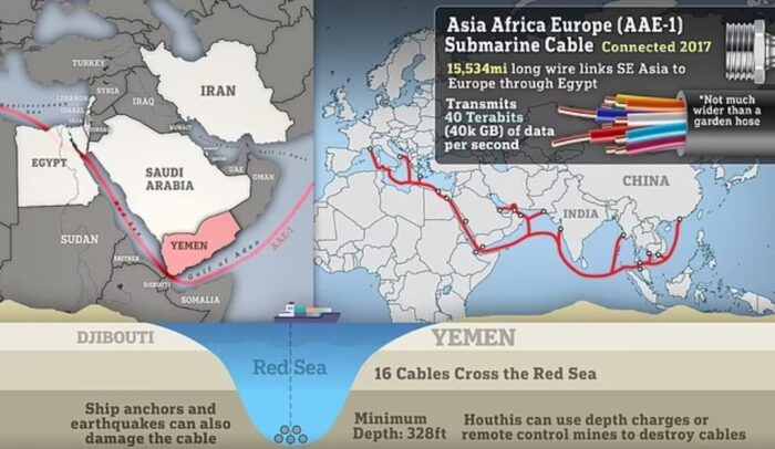
Could the Houthis sabotage these lines?
They almost certainly would if they could. The group has reportedly claimed that they have easily accessed maps showing the confluence of undersea communications cables running past their coastline, as they pass through the Bab al-Mandab Strait which, at its narrowest, is just 20 miles (32km) wide.
The US and Russia are both thought to have the naval capability to cut them. This involves deploying a deep-sea submersible from a mothership and then using what are, in effect, a giant pair of scissors for severing the cables on the ocean floor. However, it would be more difficult for the Houthis to do.
Iranian-backed Houthi militants in Yemen could try to sabotage internet cables in the Red Sea carrying nearly one fifth of the world’s web traffic, according to a spate of new warnings. Yemen’s government warned that the Red Sea is ‘one of the three most important meeting points for cables’ on the globe and the Houthis pose a ‘serious threat to one of the most important digital infrastructures in the world.’ It came after a Houthi social media channel published a map showing the routes of various cables through the Red Sea, Gulf of Aden, and the Arabian Sea. The map was accompanied with the ominous message: ‘It seems that Yemen is in a strategic location, as internet lines that connect entire continents – not only countries – pass near it.’
There are warnings Houthis could work out a way to cut internet cables in the Red Sea carrying 17 percent of the world’s web traffic; Some of the cables are only 328ft below the surface, sparking fears the Iran-backed group may be able to target them.
In March 2024, four undersea cables in the Red Sea were severed, disrupting an estimated 25 percent of telecommunications traffic between Asia, Europe, and Africa and causing a major connectivity crisis. In September 2025, several subsea fiber-optic cables were cut in the Red Sea, degrading internet connectivity across the Middle East and Asia and prompting complaints spanning the United Arab Emirates, Saudi Arabia, India, and Pakistan.
Key Details on the 2025 Red Sea Cable Cuts:
- Affected Infrastructure: Major cables affected included the South East Asia–Middle East–Western Europe 4 (SMW4) and the India-Middle East-Western Europe (IMEWE) systems.
- Impacted Regions: Significant slowdowns and connectivity issues were reported in India, Pakistan, and several Gulf nations.
- Cause & Context: While initially suspected to be related to ongoing Houthi rebel attacks on shipping, experts primarily attribute the damage to a commercial ship dragging its anchor.
- Repair Time: Repairs can take several weeks due to the need for specialized, scarce repair ships to locate and fix the cables, often in complex underwater environments.
______
Baltic sea:
Since October 2023, there have been at least 11 reported instances of damage to submarine cables in the Baltic Sea. Table below displays data on the cables in the Baltic Sea that have been suspected of intentional damage. The data includes the date of incident, cable name, length in miles, owners, and supplier.
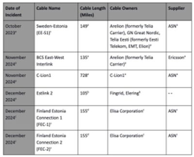
Geopolitical Landscape in the Baltic Sea Region:
Russia’s 2022 invasion of Ukraine ushered in a new geopolitical reality for the Baltic Sea region, as it has forced the bordering countries to confront a rapidly shifting security landscape. In response, Sweden and Finland made the unprecedented decision to join the North Atlantic Treaty Organization (NATO), creating a “NATO Lake” as nine out of the ten countries in the region are NATO members (Kayali, 2023). As a result of NATO’s hold on the Baltic Sea nations strengthening and Moscow’s persistent perception of NATO expansion as a strategic threat to its interests, tensions within the region have increased in an already inflamed security environment (Rahr, 2025).
_
The Baltic Sea is a shallow body of water, with an average depth of only about 180 feet (Brennan, 2025) The shallow depth makes the subsea cables more accessible to potential malicious actors because they lay closer to the surface. The Baltic Sea is also a central commercial trading hub, with as many as 4,000 ships passing through daily (Brennan, 2025). The combination of shallow depth and significant shipping traffic makes the Baltic Sea regions subsea cables more susceptible to intentional or unintentional damage. The accessibility of subsea cables to hostile actors, combined with rising tensions between Russia, the Baltic Sea nations, and NATO has created a geopolitical hotspot.
_
Within the Baltic Sea region, the primary threat actor to subsea cable infrastructure is Russia. The region is known as the “Achilles heel” of Europe because it is particularly vulnerable to Russian attacks due to its proximity to the ports of St. Petersburg and the Kaliningrad enclave (Desmarais, 2024). A comprehensive report released in April 2023 by Sweden’s Television et al. (2023) outlines Russia’s decade-long large-scale activities mapping critical infrastructure in the North and Baltic Sea. The report specifically highlights the operation of 50 Russian ships in these waters, equipped with surveillance and advanced technology (Motrunych, 2023). Many of these ships were operating without their Automatic Identification System (AIS) enabled—a system crucial for ship crews to know their location and those of surrounding ships. The manipulation of this data, also known as AIS spoofing, creates potential for disorder and collisions, and undermines maritime order as it is difficult to take retaliatory measures against these vessels (Braw, 2024; Motrunych, 2023).
Coupled with Russia’s persistent subsea mapping is its rapidly advancing naval capabilities. Stationed in Olenya Guba, off the coast of the Barents Sea, is Russia’s military fleet of special-purpose vessels (Trakimavičius, 2021). These advanced vessels include intelligence ships, auxiliary submarines, and reconnaissance vessels that can hold deep-diving submersibles and drones for subsea engineering missions, all under the operations of Russia’s General Staff Main Directorate for Deep Sea Research (GUGI) (Trakimavičius, 2021). Russia’s increasingly confrontational nature and expansion of naval fleets and equipment are exacerbating the Baltic Sea countries’ concerns about cable spying and sabotage.
______
Taiwan straits:
Subsea cable damage near Taiwan, frequently caused by Chinese ships, has severed internet connectivity for residents multiple times. Taiwan has been grappling with the issue of frequent undersea cable disruption, possibly caused by sabotage. Between 2019 and 2023, Taiwanese authorities reported 36 cases of submarine cables being damaged by suspicious foreign vessels. As of 2025, two incidents of undersea cable damage have already been reported, with indications suggesting possible intentional sabotage. In June 2025, Taiwan sentenced a Chinese national to three years in prison for intentionally damaging its undersea cable. This persistent threat has prompted the Taiwanese Navy and Coast Guard to launch 24-hour patrols on 11 September 2025 to continuously monitor the 24 undersea cables critical to Taiwan’s internet connectivity.
______
Modes of sabotage:
-1. Physical destruction:
Several modes of attack on the cable infrastructure are thinkable. The most important are scenarios of physical destruction. This can either be of a single cable or a coordinated attack on several cable connections as well as landing stations and repair infrastructure.
Attacks on cables can be carried out in different ways. Firstly, by weaponizing civil vessels, including research vessels, fishing vessels, transport vessels or leisure yachts, and using improvised cutting devices (ICDs) such as anchors and dredging devices. Such forms of attack do not require technologically sophisticated capabilities, such as undersea capabilities, and are easy to implement, given that vessels can be hidden in common marine traffic. The main way of preventing such attacks is through surface surveillance of civil maritime activities and the identification of anomalous behaviour.
A second form of attack is through undersea explosives. These can be carried out by using military-grade naval mines or maritime improvised explosive devices (MIEDs) that can be remotely triggered. MIEDs, in particular, are easy to manufacture and cheap in production. Considering the physical structure of the cables, already low explosive strength can interrupt a cable connection. Operating and placing mines require skills in handling explosives and minor undersea capabilities (divers). Preventing such attacks is more difficult and requires a combination of surface and undersea surveillance as well as mine-hunting capabilities to detect and destroy explosives.
The third form of attack is through submersible boats, crafts, or military-grade drones and submarines, which can be manned or unmanned. Submersible technology is increasingly widespread and readily available in the diving industry. Also, criminal organisations have reportedly been constructing and using submersible assets for smuggling operations. This indicates that such technology is not only available to high capability naval forces. Submersible assets can be used to place mines and MIEDs and to employ higher-end technologies, such as self-propelled underwater weapons (torpedoes) and prospectively chemical or laser weapons. Submersibles are more difficult to detect and require sophisticated underwater surveillance infrastructure across the entire length of cables.
Another form of attack does not directly target the undersea cables but the broader infrastructure on land. Landing stations in which the undersea cable connects to the land are particularly vulnerable sites, with attack scenarios ranging from cutting power supplies to the detonation of improvised explosive devices to missile attacks. Such attacks are likely to imply significant damage and are difficult to repair in a short time.
A related potential target is the wider repair and maintenance infrastructure of cable ships and depots. As shown, only three cable ships are based in the European Union, with an additional one based in the UK. Ships and depots are vulnerable to the entire spectrum of weapons used on land (e.g. improvised explosive devices, missiles) and against marine vessels (MIEDs, torpedoes, missiles). Given the importance of the repair infrastructure, a concerted attack against cables and the regional repair ships is a scenario that would imply a significant outage of connectivity.
This indicates that attacks on the cable infrastructures can be low-cost operations that do not necessarily require high-end capabilities unless carried out exclusively on the underwater level. The planning and implementation of a major coordinated attack scenario to go unnoticed, however, implies considerable organizational capabilities in planning and coordination across different locations.
-2. Data theft and intelligence:
Another scenario, which is frequently mentioned in the media and elsewhere, concerns the tapping into cables to derive, copy or obfuscate data for intelligence purposes. Tapping the cables at sea is highly unlikely because it is technically challenging. According to observers, ‘it is not publicly known whether any country is even capable of it’. While technological capabilities exist in different forms, it is for pragmatic reasons that make tapping an unlikely scenario with a direct impact and suggest that this could be an exaggerated threat. Moreover, attempts to tamper with a cable would most likely not go unnoticed by the cable operator, given that the majority of cables have surveillance to identify disruption. In consequence, the scenario of information theft, spying, and intelligence operations targeting cables at sea is rather unlikely.
Yet, multiple parts of the undersea cable supply chain can potentially be compromised, enabling the interception of data, surveillance, and traffic disruption. Cable building companies can potentially insert backdoors, install surveillance equipment, and place disruption triggers into the components of a cable before the cable is deployed. Pragmatically, onshore landing stations and facilities linking cables to terrestrial networks are more accessible and more vulnerable targets of spying and intelligence operations.
-3. Digital means:
A third scenario concerns the use of cyber weapons to target the technical operability of the undersea cable infrastructure. There are numerous ways in which cyber-attacks can be carried out against the network. One of the most significant cyber threats is linked to the reliance on remote network management systems. As network management systems are often connected to the internet and rely on HTTP and TCP/IP protocols and non-proprietary software, they become susceptible to a range of cyber threats. Hacking into network management systems can provide attackers control of multiple cable management systems, visibility of networks and data flows, knowledge of physical cable vulnerabilities, and the ability to monitor, disrupt, and divert traffic. Network Operation Centres, remote access portals, and other systems needed for the functioning of the cable network – such as electrical power, routers, heating, ventilation and air-conditioning – are also potential cyber-attack vectors.
______
______
The severity of the consequences of a cable fault depends on four key factors:
- Redundancy level
The more alternative land and undersea cables there are to balance out the loss of bandwidth from a broken cable, the higher the probability of uninterrupted data traffic. Island territories characterised by zero or only one redundancy to a submarine cable are hence particularly vulnerable. In the future, low-earth-orbit satellite internet technologies might provide part of the answer to provide emergency redundancy.
- Repair capacities
A key factor is the availability of repair capacities. The availability and distance to repair capacities, including cable laying and repair vessels, trained personnel, and material, determine how long a break prevails.
- Simultaneity of incidents
Since they are often co-located, several submarine cables can sometimes break simultaneously, most conceivably during large natural disasters or through coordinated acts of sabotage. In these scenarios, repair capacities can become scarce, resulting in longer repair times. Higher availability of redundancies – more submarine cables – and alternative internet-providing options are then required.
- Internet usage and blackout preparedness
States marked by very high rates of internet use and large shares of digitalised processes, such as the EU member states, risk suffering severely from an internet outage. Scenario exercises may help states prepare a strategy for the occurrence of total internet blackouts – potentially resulting from submarine cable breaks.
______
______
Location of cable faults:
The ICPC and several private organizations maintain records of cable faults. To date, there is no central global database of all fault records, so it is difficult to know exactly how many faults occur in a given year. However, based on records spanning several decades, it may be estimated that 150– 200 cable faults occur annually world-wide. Figure below indicates the distribution of faults caused by external forces (external aggression) including seabed movement and abrasion. These patterns were taken from a global database of 2,162 cable faults going back to 1959. It is clear that most faults occur on the continental shelf, near land in water depths of less than 100 m. This is to be expected, since the vast majority of human activities that involve seabed contact take place in relatively shallow waters. The remaining faults occur across a wide range of depths, including oceanic areas more than 4,000 m deep.
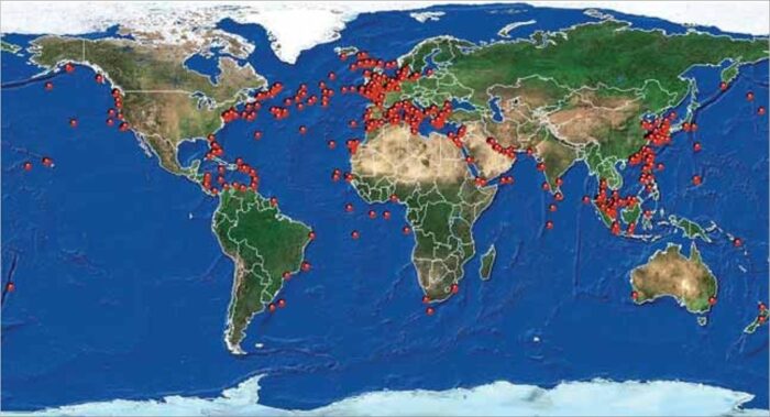
Figure above shows Global pattern of external aggression cable faults, 1959–2006.
Source: Tyco Telecommunications (US) Inc.
_
The Complexities of Cable Cuts:
Not only can cable cuts occur for various reasons, but they can also happen at any point along the cable, from along the shore to deep on the ocean’s floor. In the high seas, the cables lie at an average depth of 3,600 meters, and they can go down as far as 11,000 meters. However, research has revealed that most cuts occur in the shallow waters (0–100 meters). In fact, the deeper the ocean, the smaller the likelihood of cable cuts (see figure below). Building resilience of undersea cables requires a nuanced approach with a particular emphasis on high-risk areas.
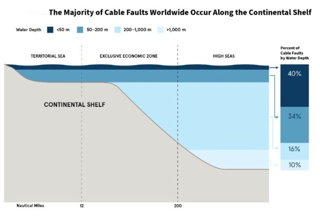
Figure above shows that the Majority of Cable Faults Worldwide occur along the Continental shelf.
_
The geographical distribution of major cable break incidents, illustrated in Figure below, has shifted dramatically from 2005–2021 to 2022–2025, mirroring the growing link between these attacks and geopolitical tensions. Between 2005 and 2021, suspicious cable breaks appeared to be random, mainly unrelated to geopolitical tensions or strategic choke points, instead coinciding with domestic incidents.
Figure below shows the Density and Location of Suspicious Cable Breaks (2005–Present):
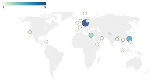
As Figure above illustrates, the nine recorded breaks prior to 2022 were scattered across six regions—Southeast Asia, South Asia, North Africa, Europe, the Caribbean, and North America— affecting eight countries: the Philippines, Indonesia, Vietnam, Bangladesh, Egypt, Norway, Jamaica, and the United States.
Only Egypt and Southeast Asia saw multiple incidents. Egypt’s 2013 incident is the only break that appeared strategically motivated due to its location in a geographic choke point (Arthur, 2013). All other incidents. appeared tied to domestic events rather than geopolitical motives, such as the 2013 Indonesia and 2007 Vietnam breaks, which were linked to ongoing cable smuggling operations.
_
An additional challenge is the fact that undersea cables traverse multiple geographic and maritime zones, extending from terrestrial areas to the high seas. This means that cables span multiple national and international governance jurisdictions, which can create regulatory complexity and uncertainty. Although undersea cables are primarily a private sector investment, there are shared interests in their security, meaning their repair and efficacy requires a multistakeholder approach. Many different authorities are involved in subsea cables, including national authorities for telecommunications, security, and maritime areas. When a cable cut occurs, jurisdiction matters for many reasons, including for accessing undersea cables and for dealing with recourse. A key legal tenant for submarine cables is the United Nations Convention on the Law of the Sea (UNCLOS), which demarcates the ocean’s boundaries and provides a legal framework for laying and repairing submarine cables.
Another complexity is that repairs are expensive. The cost of repairing a submarine cable average between $1 million and $3 million and involves specialized cable ships with highly trained crews that cost tens of thousands of dollars per day, alongside the costs associated with replacing damaged cables and other expenses like permits. In addition, it takes time to mobilize repair vessels, especially for African countries. For instance, the first repair ship that responded to the West African cuts arrived after three weeks. Globally, there are less than one hundred cable repair ships, and only three serve the African continent. Only one of those vessels (Léon Thévenin) is based at a port along the African coast. This creates complications, especially when the ship is already deployed to undertake other services across the continent, as happened in 2023 when two cables serving Southern Africa were severed off the coast of Democratic Republic of the Congo.
______
______
Natural Hazards to submarine internet cables:
Throughout human history, people have always faced natural hazards in various forms. From flooding to storm surges, to earthquakes, tsunamis, landslides, wildfires, and volcanic eruptions. The ocean encompasses a suite of dynamic environments that extend from the coast to the abyss. All are exposed to natural hazards, which are defined here as naturally occurring physical phenomena caused by rapid- or slow onset events, influenced by atmospheric, oceanic and geological forces that operate on timescales of hours to millennia (modified from UNESCO, 2006). Such phenomena include weather-related disturbances, earthquakes, volcanic eruptions and, in the longer term, climate change. Subsea cables and their landing stations are vulnerable to damage by natural hazards, including storm surges, waves, cyclones, earthquakes, floods, volcanic eruptions, submarine landslides and ice scour. Natural hazards may further be characterised as either instantaneous events — which are essentially one-off disruptions — or long-term hazards that manifest over large periods of time, such as sea-level rise.
Instantaneous Events:
Instantaneous events occur as one-off events and have tremendous destructive force. Such events may occur either underwater or onshore, often with spillover effects from one onto the other. Underwater instantaneous events primarily damage the ‘wet plant’ of the cable system, i.e., the submarine cable itself. Damage could entail the exposure of previously buried cables, excessively burying cables beneath the mobilised sediment, or the cables suffering from abrasion or chafing. On the other hand, onshore instantaneous events pose a greater hazard to onshore infrastructure such as the beach manholes and the cable landing stations. The following hazards are considered to be instantaneous hazards:
Submarine Landslides:
These are essentially downslope movements of sediment or rock when stresses acting downslope exceed the sediment strength on the slope. They mobilise hundreds to thousands of cubic kilometres of sediment volume and rock along slopes, and frequently occur in active river deltas, submarine canyons, volcanic islands, and on the open continental shelf. Submarine landslides may be triggered by events such as earthquakes, volcanic eruptions, cyclones and major storms, rapid sediment-deposition by river floods, gas pressures, human activity, etc. They may even occur without instantaneous triggers due to factors such as weakening sediment strength and increasing stresses. It is often the submarine landslide that is the primary cause of damage to underwater cables, and it is other factors such as earthquakes, cyclical wave action, etc., that are usually responsible for the occurrence of submarine landslides. The impact of submarine landslides on seabed infrastructure is so large and relatable that researchers have developed a methodology to study submarine landslides using historically available cable-break data.
Turbidity Currents:
Another form of sediment flow are turbidity currents. These involve the downslope transport of a dilute suspension of sediment grains, i.e., a mix of sediment and water, with speeds ranging from 28 metres per second at mid-slope to 6 metres per second in abyssal plains. Turbidity currents may begin as submarine landslides and then transform into more fluid sediment flows after mixing with seawater capable of travelling much longer distances. As a result, they can have a significantly larger impact on seabed infrastructure both at distance and at depth. In 2006, the Pingtung earthquake, whose epicentre lay offshore from southwest Taiwan, generated powerful turbidity currents that damaged fourteen cables at depths ranging from 612 metres to 3250 metres over a period of fourteen hours. The formation of turbidity currents depends on factors similar to the formation of submarine landslides, with earthquakes, tropical cyclones, storm waves, cyclical wave action, and river sedimentation, being primary causes. The velocity of the turbidity current depends upon the bathymetric slope across which it is moving and can have a significant destructive influence on cable systems.
Earthquakes:
Earthquakes, as a natural hazard, threaten not only the submarine cable underwater infrastructure but also associated onshore infrastructure. Much depends upon the position of the epicentre — focal point — of the earthquake. Earthquakes can give rise to submarine landslides and turbidity currents which, as highlighted above, have a significant impact on underwater cables, especially those unarmoured ones that are located at greater depths. Earthquakes can also damage the beach manhole or cable landing station either from direct impact or from the creation of powerful tsunamis. History is replete with examples of extensive damage caused by earthquakes, from the 1929 Grand Banks earthquake, and the 2003 Boumerdès earthquake off Algeria, to the 2006 earthquake off Taiwan, which disrupted multiple cables at once.
The December 2006 earthquake off southern Taiwan focused the world’s attention not only on the human tragedy, but also on the impact of natural hazards on the submarine cable network. The magnitude 7.0 earthquake triggered submarine landslides and dense sediment-laden flows (turbidity currents), which passed rapidly down to the +4,000 m-deep ocean floor, breaking nine fibre-optic submarine cables enroute (Figure 1).
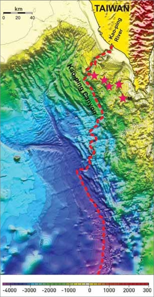
Figure above shows that on 26 December 2006, a magnitude 7.0 earthquake and aftershocks (pink stars) set off several submarine landslides off southern Taiwan. These slides transformed into fast-flowing mud-laden currents that sped down Kao-ping submarine canyon (red dashes) into a deep-ocean trench: a distance of over 300 km. Nine cables were broken enroute, disrupting international communications for up to seven weeks.
Southeast Asia’s regional and global telecommunications links were severely disrupted, affecting telephone calls, the internet and data traffic related to commerce and the financial markets. Such natural hazards generate less than 10 per cent of all cable faults, but fault occurrence rises to around 30 per cent for cables in water deeper than c.1,500 m, i.e. beyond the main zone of human off- shore activities.
Cyclones and Storm Surges:
Cyclones (also known as hurricanes and typhoons) are associated with extreme rainfall and high wind speeds. They have particularly adverse impacts upon coastal infrastructure associated with submarine communication cables. This manifests in the form of storm surges and high wind speeds. A storm surge is the abnormal rise of seawater level during a storm caused by powerful winds pushing water onshore. The inundation caused by the storm surge can flood — and potentially damage — local infrastructure. This was observed in Puerto Rico after Hurricane Maria (a Category 5 hurricane) flooded a cable landing station due to a storm surge of 1.8 to 2.7 metres. The cable network had to be powered down to prevent equipment damage. This led to loss of connectivity not only in Puerto Rico but also in other South American States that relied on this cable landing station as a gateway for transit. Since the beach manhole(s) and cable landing station(s) form a point of congregation for multiple cables, any significant damage to these will have a serious impact on the national and regional communication network than might be the case where damage occurs to individual cables. A study, in fact, noted that “storm surges are among the most costly and deadly natural hazards, and can episodically raise coastal water levels by up to 4 metres due to extra-tropical weather systems, and over 9 metres when caused by tropical systems”. A substantial portion of critical infrastructure is susceptible to coastal flooding and climatic-prediction models indicate that this susceptibility is likely to increase. The study also noted that the “effect of cyclones on shipping can also pose a risk to subsea cables. Roughly 13 percent to 40 percent of ships that that attempt to “ride out” typhoons off major ports have been estimated to drag their anchors. As such they plough the seabed, endangering cables in the vessels’ path. For example, in 1979, anchor dragging during Typhoon Hope damaged five subsea cables in Hong Kong Harbour. In fact, storm surges and cyclones have impacts beyond just flooding, especially in the form of enhanced coastal erosion.
Coastal Erosion:
Coastal erosion has an impact on shore-based infrastructure especially the beach manhole segment. This can erode the beach manhole cover and expose cables to wave action, the terrestrial portions of which may not be as resistant to seawater as their submerged counterparts. Further, cable landing stations right on the shore could also face significant structural challenges in the face of a receding shoreline. In Argentina, due to the amount of erosion, a beach manhole had to be relocated farther inland and re-buried deeper in the beach to reduce chances of exposure. Coastal erosion can occur up to several metres per year, with south Asia figuring as one of its hotspots. Given the proximity of cable landing stations to the mean sea-level, roughly 6 per cent of cable landing stations were found to lie within ten metres of the present mean sea-level, and 4.9 per cent lie within two metres, with the majority of cable stations (80.6 per cent lying on slopes less than four degrees— this threat acquires significant proportions.
______
How subsea cables were affected by the most volcanic eruption ever recorded:
- On the 15th January 2022, an eruption in the South Pacific Ocean escalated to produce the most explosive volcanic event this century with almost no warning, creating impacts that were felt worldwide.
- The eruption triggered tsunamis that devastated Tongan islands and travelled across the ocean, ejected a plume that extended above the stratosphere, and atmospheric shockwaves that travelled multiple times around the globe.
- One of the most profound impacts did not occur on land, but instead, surprisingly deep under the surface of the ocean; affecting underwater telecommunications cables.
- Data traffic between the Kingdom of Tonga and the rest of the world suddenly came to a halt. The only submarine cable connecting Tonga to the rest of the global network was damaged just over an hour after the biggest explosion of Hunga volcano, effectively shutting down an entire nation’s international digital communications.
- Due to extensive damage to Tonga’s international cable, people could not communicate with their families and loved ones, business transactions stopped, and international aid efforts were hindered, all in the midst of a volcanic crisis.
______
Sharks (fish bite):
Records extending from 1877 to 1955 reveal that 16 faults in submarine telegraph cables were caused by whales (Heezen, 1957; Heezen and Johnson, 1969). Thirteen of the faults were attributed to sperm whales, which were identified from their remains entwined in the cables. The remaining faults were caused by a humpback, killer and an unknown whale species. In most instances, entanglements occurred at sites where cables had been repaired at the edge of the continental shelf or on the adjacent continental slope in water depths down to 1,135 m. However, whale entanglements have nowadays ceased completely. In a recent review of 5,740 cable faults recorded for the period 1959 to 2006 (Wood and Carter, 2008), not one whale entanglement was noted (see figure below). This cessation occurred in the mid-1950s during the transition from telegraph to coaxial cables, which was followed in the 1980s by the change to fibre-optic systems.
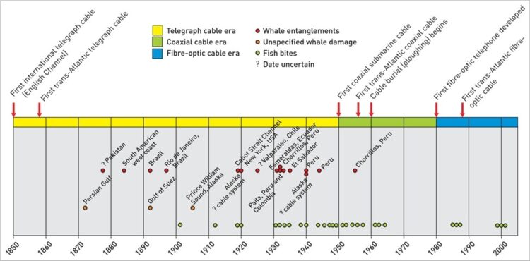
Figure above shows Interaction of whales and fish with submarine cables over time. The cessation of whale entanglements coincided with the improved design and laying techniques of the coaxial and fibre-optic eras. In contrast, fish bites (including those of sharks) have continued. Essentially, sharks and other fish were responsible for less than 1% of all cable faults up to 2006. Since then, no such cable faults have been recorded.
Less speculative are the cold facts from records of cable faults; those records coming mainly from ICPC members, who represent 98% of the organisations involved with the world’s subsea telecommunications cables. Three studies reveal a marked decline in the number of faults caused by fish bites including those of sharks.
-1. For 1901 to 1957 – a period dominated by subsea telegraphic cables – at least 28 cables were damaged.
-2. During 1959 to 2006 – a span that encompasses coaxial cables, which were replaced by fibre-optic systems in 1988 – around 11 cables needed repair. Fish bites accounted for 0.5% of all cable faults.
-3. The latest analysis, covering 2007 to 2014, recorded no cable faults attributable to sharks.
That marked reduction in faults is consistent with improved cable design and other measures to protect cables such as burial beneath the seabed. The negligible amount of fish bite damage contrasts strongly with ships’ anchoring and fishing activities, which account for 65-75% of all cable faults. Other faults relate to natural phenomena, such as subsea landslides and ocean currents (less than 10%), cable component failure (5%) and “cause unknown” (10-20%). It is unlikely that shark bites are masked in the “cause unknown” category, because bites leave evidence in the form of teeth imprints or actual teeth embedded in a cable’s sheathing.
The first recorded shark bites of a deep-ocean fibre-optic cable occurred off the Canary Islands in 1985 to 1987. These pioneering systems were damaged by small sharks biting through cable’s polyethylene sheath. Testing by Bell Laboratory scientists showed the culprit was the deep-dwelling, crocodile shark (Pseudocarcharias kamoharai) that occupied water depths of 1060-1900m. Those events led to design improvements of the cables’ protective sheathing that effectively eliminated the problem.
_______
Climate Change and Sea Level Rise:
Climate change and sea level rise are not classified as instantaneous events as their effects are felt progressively over a period of time. The impact of climate change also manifests itself in the increasing intensity and frequency of current hazards. Therefore, disaster-resilience needs to not only factor the occurrence of the hazards but also the manner in which it be impacted by climate change. Due to greater variations in sea level at times of tropical cyclones and storm surges, climate change and sea level rise will particularly affect onshore cable landing infrastructure. Similarly greater rates of coastal erosion occasioned by higher sea levels threaten the beach manhole cover. Climate change additionally affects and modifies human behaviour, since rising oceanic temperatures are affecting entire food chains from phytoplankton upwards, forcing their horizontal and vertical migration, thereby compelling humans to fish in deeper and more distant waters, where seabed cables lie unarmoured and are therefore more vulnerable. Hence, each scenario of climate change variability will be associated with a corresponding risk, and an analysis factoring projected scenarios of climate change needs to be conducted.
_
Climate change has led to widespread and rapid changes across the entire Earth System, including unprecedented changes in the atmosphere, ice caps, across ecosystems, and in the ocean. Subsea cables and the shore based stations that connect them to terrestrial networks are typically designed to operate over 20-30 years. It is increasingly recognised that the risks posed to this infrastructure will change as a result of future climate change and its knock-on effects. Sea-level rise is projected to negatively affect various economic sectors, including by damaging electrical and telecommunication support facilities and (as a result of rapid rates of sea level rise) low-lying communities, including those in coral reef environments, urban atoll islands and deltas, and Arctic communities, as well as small island developing States and the least developed countries, are particularly vulnerable.
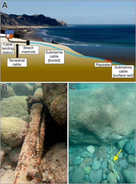
Figure above shows Cable system architecture and examples of damage. (A) Schematic of a submarine fibre-optic cable system as it transitions from the ocean to the beach manhole and landing station. From there, the cable connects to the terrestrial network. (B) Photograph of cable protection (cast iron casing) damaged by mobilisation of the seafloor substrate. (C) Boulders moved over a cable (labelled with yellow arrow) by Hurricane Irma.
_
Sea level is rising on a global basis as a result of the increased melting of ice sheets and glaciers and expansion of the ocean as it warms. The rate of sea level rise has increased over recent decades. The rate of global mean sea level was 8 mm per year between 2006 and 2015, which is 2.5 times the rate for the period between 1901 and 1990 (1.4 mm per year). However, this rate of sea level rise is not geographically uniform, and it varies around the world due to land ice loss, and changes in ocean warming and circulation. In a few locations, vertical movement of the land may occur, instead creating a relative drop in sea level. This occurs in areas where ice sheets have retreated and the land mass ‘rebounds’ and moves upwards. Sea level rise may be accelerated due to some human activities, such as where ground water is extracted in sufficient volumes.
- A previous study examined the impacts of sea level rise on terrestrial internet infrastructure in the USA, finding that projected sea level rise may submerge thousands of kilometres of onshore cable that is not designed to be immersed in water by 2030 as a result of sea level rise.
- Offshore cables are designed to be resistant to sea water, so it is the shore based landing stations that need to be designed to cope with future rates of sea level rise.
- Relative sea-level rise is projected to be far more pronounced in certain regions, including the Gulf of Mexico, NW Australia, Pacific islands (e.g., Hawai’i, French Polynesia, Samoa, Fiji), SE Asia (e.g., Philippines, Indonesia), Japan and West Caribbean.
- Other areas such as the Mediterranean and Red Sea, much of NW Europe and the majority of North and South American coastlines will experience lower rates of sea level rise.
- Some localised parts of high latitude regions (e.g., Alaska, Norway) are likely to experience relative sea-level fall, rather than rise, as a result of on-going continental rebound following the past removal of ice sheets.
_
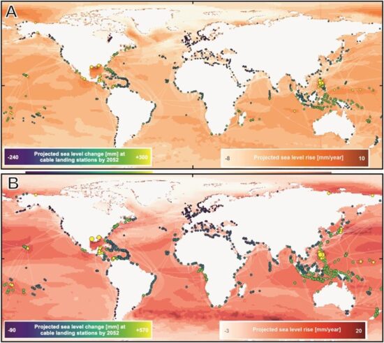
Figure above shows Projected rates of sea-level rise and elevation change at cable landing stations. Cables are shown in white.
(A) Sea-level rise under IPCC low emissions (SSP1–2.6) scenario (brown gradational colouring), annotated with projected sea-level rise by 2052 at existing cable landing stations (blue-yellow coloured circles that are also scaled proportionally to sea-level rise).
(B) Sea-level rise under IPCC high emissions (SSP5–8.5) scenario (red gradational colouring), annotated with projected sea-level rise at existing cable landing stations (blue-yellow coloured circles that are also scaled proportionally to sea-level rise). Sea level data from Intergovernmental Panel on Climate Change (2021).
_
While sea level rise happens at a relatively slow rate, even small increases in sea level can make other hazards more severe. Indeed, sea level rise is often referred to as a ‘threat multiplier.’ One of the most significant hazards that will become more severe as a result of sea level rise is storm surges. Storm surges created by extra-tropical cyclones can raise sea levels by up to 4 m, and by over 9 m in the case tropical storms.
As sea levels rise, storms become more frequent and weather patterns change, coastal regions are under increasing stress, which can result in an increase in landward erosion of shorelines. It has been estimated that coastlines will retreat by an average of 128 m by 2100; however, as in the case of sea level, the picture is far from uniform.
_
The subsea cable industry is already adopting various mitigation and adaptation measures to proactively adapt to or protect against adverse impacts of climate change. Some of these examples include:
- Increased armouring and/or cable burial protection at shore ends where erosion is worsening.
- Mitigation against threats related to deep sea fishing, including liaison with fishers, desktop study, route clearance of discarded fishing gear, and use of more resistant cable.
- Avoidance of low-lying areas for landing points, beach manhole cover and cable landing stations.
- Avoidance of submarine canyons where possible, and where they must be crossed, then identify the most appropriate crossing points by understanding the potentially hazardous flows that may run along them.
- Local knowledge ascertained from site visits regarding environmental conditions and historical events.
- Use of model outputs of future projected changes in ocean conditions to pinpoint hazard hotspots.
- Geographical Information System (GIS) analysis using various geospatial datasets that are incorporated into desktop studies to identify the optimal routes and landing points.
It is clear that the impacts of climate change will be diverse, but geographically variable, and are already being felt. Being aware of the current and future challenges will ensure that the global network continues to remain resilient and adapts as conditions change.
_____
_____
Impact of cable fault of subsea cables:
If undersea internet cables are cut, it causes slowdowns, increased latency, and potential outages for internet and communications in affected regions, impacting businesses, cloud services, and personal use, though redundancy often reroutes traffic; repairs involve specialized ships and take weeks, highlighting vulnerability and geopolitical risks, as seen in Red Sea incidents.
For Common Users:
- Slower speeds during cable disruptions
- Dropped video calls and streaming issues
- Delays in online payments or banking
This is not just a tech issue—it affects every digital user in the areas affected by cable fault.
______
If undersea cables are severed, the consequences can be severe across multiple sectors. Here’s what could happen:
-1. Global Communications Disruptions
- Internet & telecommunications: these cables carry global data traffic, so disruptions could lead to massive internet outages, affecting businesses, government operations, and individuals.
- Financial systems: international financial transactions, including those handled by SWIFT, rely on these cables, potentially causing market instability. Every day, the Society for Worldwide Interbank Financial Telecommunications (SWIFT) transmits 15 million messages between more than 8,300 banking organizations, securities institutions, and corporate customers across and within upwards of 195 countries worldwide.
- Cloud services & streaming: many cloud services depend on these networks, leading to disruptions in business operations and entertainment.
-2. Economic & Trade Impact
- Shipping & logistics: port operations, supply chain visibility, and vessel tracking systems could be compromised, delaying global trade.
- Stock markets & banking: delays in transaction processing can disrupt international markets and currency exchanges.
- Remote work & IT services: affected businesses may lose access to critical remote infrastructure, impacting global workforces.
-3. Military & National Security Risks
- Intelligence & defense coordination: many countries rely on undersea cables for military communications and intelligence sharing. A disruption could hinder strategic operations.
- Cybersecurity vulnerabilities: if cables are tampered with, data interception or cyber espionage could occur.
- Navigation & satellite data transmission: some GPS-related military applications rely on undersea cable-backed infrastructure.
-4. Political & Geopolitical Tensions
- Accusations & retaliations: if sabotage is suspected, it could escalate conflicts between nations.
- Economic warfare: a hostile state or group could use cable sabotage as a form of hybrid warfare, disrupting adversaries without direct military engagement.
-5. Financial impact
- Businesses may suffer financial losses due to disrupted operations, missed opportunities, and decreased productivity.
- Extended outages can harm a company’s reputation and erode customer trust.
- Companies relying on global supply chains may face delays in shipments and communication with suppliers.
- Low internet connectivity can lead to downtime for online services, affecting customer experience and revenue.
_____
_____
Cable Fault Localization Techniques:
Generally, there is no global system that can detect cable failure before it happens, or even warn related parties to take attention in accordance with any weak signals transfer from a certain cable. Unfortunately, detection of cable failure is known after severing which definitely impacts world industrial and economy causing loss of telecommunication connection between countries and that disrupts business activities such as online shopping, banking, financial transaction, etc. Another issue that is worth mentioning here is that in many countries there are always many agencies\parties involved in the submarine cable projects. For instance, in the United States, more than seven agencies are involved in that including Central Intelligence Agency and Department of Navy. Therefore, if any cable failure occurs, it is very cumbersome to coordinate between all parties to detect the exact location of that failure.
_
Whatever the ultimate failure mode might be, finding a fault in a cable that might be as long as the Earth’s circumference and could be 8,000 meters under the sea is no easy task. Cables typically come ashore multiple times along their length, and each landing has monitoring equipment to watch the vital signs of each segment. That isolates the fault to a specific segment of cable, but to dispatch a repair ship, the cable owner needs to pinpoint the fault as precisely as possible.
Undersea cable breaks are identified by immediate, large-scale internet service disruptions or slow speeds in affected regions. Operators detect the exact location using monitoring software that measures voltage drops, or by sending light pulses (Optical Time-domain Reflectometer) through the cable to measure reflection timing. Accurate fault localization is critical for efficient repair operations. Multiple complementary techniques are employed:
Key methods for identifying and locating breaks include:
-1. Monitoring Systems: Operators utilize network management tools that detect a sudden drop in power or loss of signal, indicating a break.
-2. Supervisory System Localization: For systems with optical submarine repeaters, the supervisory system provides initial fault localization to within one supervisory section (typically 40-80 km between repeaters). This narrows the search area significantly but requires additional precision techniques for exact location.
-3. Electrical Measurement Methods: Power feeding equipment (PFE) measurements provide distance-to-fault calculations based on DC resistance, capacitance, or voltage drop measurements. For shunt faults, the voltage drop to the fault point allows calculation of cable distance. For open faults, capacitance measurements determine the distance to the break. It uses a bridge circuit to locate earth faults and short-circuit faults.
-4. Optical Time Domain Reflectometry (OTDR): OTDR systems inject optical pulses into the fiber and analyze backscattered light to detect breaks, bends, or high-loss points. Standard OTDR is effective up to the first repeater but cannot penetrate through optical amplifiers in long-haul systems.
-5. Coherent OTDR (COTDR): COTDR provides higher sensitivity and frequency selectivity, enabling fault location beyond optical amplifiers in long-distance systems. This technology revolutionized fault localization in modern DWDM submarine systems with optical amplifier chains.
-6. Electroding: For shunt faults where the cable can still be powered, a modulated tone (typically 16.667 Hz or 25 Hz) is applied to the power feeding current. The cable ship deploys electromagnetic sensors to detect this tone and follow the cable route, even if it has moved from the as-laid position. The tone disappears or greatly reduces at the fault location.
-7. Intelligent Repeaters: These devices, placed along the cable, can provide diagnostics to locate faults.
-8. Visual Fault Locators (VFL): A bright red laser is shone through the cable, and lack of light at the other end confirms a break.
-9. AIS (Automatic Identification System): Satellite data, such as from Oceana, is used to track ships, identifying vessels that may have passed over or dragged anchors across the cable path.
-10. Time Domain Reflectometry (TDR): A “cable radar” technique that transmits high-frequency pulses to identify changes in impedance caused by breaks or short circuits.
-11. Distributed Acoustic Sensing (DAS): Distributed Acoustic Sensing (DAS) detects and locates cable faults in real-time by turning fiber optic cables into sensitive acoustic sensors, achieving up to ±10 m accuracy for subsea and underground power cables. DAS identifies faults by detecting strain, temperature changes, and acoustic vibrations caused by short circuits, Partial Discharges, or third-party interference (e.g., anchors).
-12. Voltage Pulse Reflection/Flashover Tests: High-voltage generators create sparks at the fault location, allowing detectors to pinpoint the spot, even with low-resistance faults.
_____
Figure below shows Sequential process from initial alarm to precise location of cable fault:
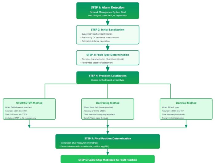
______
Submarine cable faults are classified into three primary categories, each requiring different detection and repair approaches as seen in figure below:
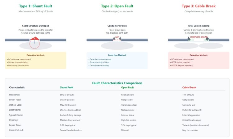
_____
SS-TDR:
Spread-spectrum time-domain reflectometry (SS-TDR) is often used to locate and characterize a fault on active cables. Traditional time-domain reflectometry, which sends signals down a conductor to determine where any impedance discontinuities are by timing any reflections that come back from any impedance discontinuities along the way, can’t be used on in-use undersea cables thanks to the high voltages involved. SS-TDR, which was originally developed to detect faults in the wiring of airplanes using 400-Hz AC power, uses modulated pseudo-noise (PN) signals rather than a plain square wave pulse. The signals still bounce off any impedance changes introduced by damage, but an algorithm is used to correlate the returned PN codes with what was sent and when, making it easier to make measurements in a noisy environment. Optical TDR can also be used to locate fiber breaks, but since there are perhaps dozens of individual fibers inside a cable that would each have to be scanned, the fact that anything that would break one of them would likely breach the outer power conductor first makes it easier to just can that.
_______
DAS:
Distributed Acoustic Sensing (DAS) technology works by analyzing light traveling through fiber to detect acoustic vibrations, essentially allowing cables to “hear” their surroundings with remarkable precision—down to five-meter resolution across thousands of kilometers. Distributed Acoustic Sensing (DAS) is an emerging technology that utilizes optical fiber (OF) cables as dense arrays of acoustic sensors to detect submarine cable routes. Operators can monitor subsea cables in real-time, detecting anomalies and threats with unprecedented accuracy. This proactive approach to maintenance and monitoring enhances reliability and minimises downtime.
_
Distributed Acoustic Sensing (DAS) is an advanced sensing technology that uses standard fiber optic cables to detect acoustic, seismic, and vibrational signals over long distances. DAS transforms fiber optic cables into a continuous array of sensors, leveraging their ability to detect minute disturbances in the environment. Underwater DAS involves the use of unused or “dark” subsea fiber optic cables to sense underwater acoustic or seismic energy. A device called an interrogator transmits pulses of light along the length of the dark cable. When the light comes in contact with tiny imperfections, it is reflected back toward the interrogator (a phenomenon known as Rayleigh scattering). Acoustic or seismic energy causes strain in the cable, which in turn impacts the phase of the Rayleigh backscatter. This strain can then be sensed and measured by the interrogator.
By enabling real-time, large-scale monitoring with high precision, DAS could transform how maritime forces monitor and protect critical infrastructure, detect underwater threats, ensure domain awareness, and construct a common operational picture.
OPERATIONAL COMPONENTS:
- Fiber Optic Infrastructure: Underwater DAS systems leverage unused (“dark”) fibers within existing undersea fiber optic cables, or specially deployed cables, as a medium for signal transmission and sensing.
- Interrogator Unit: An interrogator unit sends pulses of laser light down the fiber optic cable which interact with imperfections in the fiber, creating backscattered light.
- Signal Detection: When the fiber experiences minute physical disturbances (vibrations, pressure changes, acoustic waves), the pattern of backscattered light changes, enabling the DAS system to identify the location and characteristics of the disturbance with high spatial resolution.
- Data Processing: Advanced algorithms process the backscattered signal, filtering out noise, identifying patterns, and classifying the type of disturbance.
SCIENCE AND TECHNOLOGY:
- Rayleigh Scattering: Exploits micro-scale variations in the refractive index of the fiber, which reflect a portion of the light back to the source.
- Optical Interferometry: DAS uses coherent detection techniques to measure phase changes in the backscattered light, which correspond to vibrations along the fiber.
- Spatial Resolution: Modern DAS systems achieve resolutions as fine as a few meters, allowing precise localization of disturbances over tens of kilometers.
- Signal Processing: Advanced signal processing and pattern recognition algorithms provide event localization and classification.
______
______
Section-12
Cable resilience, redundancy and protection:
A study which has been conducted by the communication security reliability and interoperability council (CSRIC) in the USA, recommended that establishment of a default minimum separation distances between an existing submarine cable and another marine or coastal activities will have an advantage to protect submarine cables. That study stated that more than five countries like United Kingdom, China, Russia, Japan, Denmark, Singapore and Indonesia have benefits. For instance, National Maritime Law in Singapore allows submarine cables owner to establish a protection area around them and if any vessels cause any break to those cables, they are responsible to indemnify cable owner. Another example is from China that also determines a specific distance zone around submarine cables such as 50 meters in harbor area, 100 meters in narrow coastal water area and 500 meters in broad coastal water. In fact, this will solve major vulnerabilities such as fishing vessels, anchoring and all marine activities which may cause submarine cable fault.
_
Another perspective of view suggested by Captain Douglas R. Burnett, a USA retired officer, that it is time for navy to look after cables under seas. He recommended that naval forces need to know how cable and cable ships operate internationally and highlighted to maritime security to close the gap indicated out of the territorial water against terrorism and piracy which in most cases pirates freed because of time consuming to bring them to justice and some political relationships. It is in advance to say that whether naval forces and maritime security playing these roles to protect undersea cables will affect positively in accordance with fast cooperation and response between all related countries. On the other hand, if political or commercial intentions conflict with related countries which are advanced in submarine cables, terrorism and piracy actions will never be under control because that requires united collaboration to be finished.
_
In early 2023, NATO defense ministers announced a plan to strengthen undersea infrastructure and prevent incidents like the one happening with the Nord Stream 1 and 2 pipelines. Their explosion, confirmed as a sabotage with explosives, is yet another example of critical undersea infrastructure that remains vulnerable to hostile intentions at the same time as being easily to disrupt. Secretary General Jens Stoltenberg announced the establishment of a Critical Undersea Infrastructure Coordination Cell at NATO. Led by German Lieutenant General Hans-Werner Wiermann, this center represents a positive initiative and starting point for the Alliance to keep building on; the face of the challenge Russia or China could pose if restoring to the disruption of allied undersea critical infrastructure.
_
On the opposite side of the globe, Taiwan is also taking significant steps to secure their undersea cables and ensure a quick response to any attack given the threat posed by China. Most recently, Taipei announced an incorporation of communication breakdowns into the war drills they usually carry out, to improve Taiwan’s response capabilities and ensure fast reaction times to any malicious attack. Among other solutions which are being under consideration, the use of high-speed satellites to boost connectivity, like Starlink’s Elon Musk’s Starlink did in Ukraine after Russian attacks, has attracted the attention of many.
_
A 2017 report sponsored by the Office of the Director of National Intelligence (ODNI) found that the majority of disruptions are caused by human activity (e.g., fishing, anchoring, dredging) and natural disasters. The ODNI report found there are few disruptions of cables in proportion to their heavy presence and use. Automated detection systems, increased redundancy of routes, and a network of repair ships has led to a high degree of resiliency in the global undersea cable network. However, the ODNI report asserted that risks are increasing, due to the heavy reliance on undersea cables, increasing volume of data transmitted through undersea cables, and technological improvements to cable systems that have created new vulnerabilities.
______
______
Resilience:
Submarine cables may be vulnerable, but they are not undefendable. Most breaks occur not from espionage or sabotage, but from accidental cuts, natural disasters, or aging equipment. While these risks can’t be eliminated, their impact can be mitigated. Redundancy is the duplication of components to prevent failure (having a backup), while resiliency is the ability of a system to recover quickly, adapt, and continue operating during disruptions. Redundancy provides spare capacity, whereas resiliency ensures survival and continuity of service despite failures. Redundancy is about having backups, while resiliency focuses on the system’s ability to withstand and adapt to disruption. The difference between network redundancy and resiliency is redundancy duplicates network devices while resiliency is the self-recovery of system failures.
_
Resilience is not a destination but a continuous process. It requires not just cables and routers but strategies and partnerships. Based on global evidence and insights from Internet Society’s Pulse research, the following principles are key:
First, invest in infrastructure diversity. Relying on a single route—especially a single submarine cable—is a recipe for disruption. Whether through additional submarine paths or terrestrial links, redundancy must be built into national networks.
Second, promote data openness and transparency. Open standards like OFDS allow all stakeholders—governments, ISPs, and civil society—to make smarter decisions. They reduce duplication, highlight risks, and promote accountability. Transit offers should inform about redundancy and security measures.
Third, decentralize Internet infrastructure. Distribute content, by hosting it locally and deploying off-net caching servers to reduce latency, keep traffic inside borders, and lessen dependence on fragile international connections.
Fourth, foster regional collaboration. As the Lisbon SubOptic conference emphasized, resilience cannot be achieved in isolation. Governments and network operators must work across borders to share intelligence, build trust, and coordinate responses.
Finally, define Internet preparedness as a national policy objective. That means tracking performance, setting goals, and adapting strategies in real time. Internet Society’s Pulse measurement tools provide a foundation, but commitment must come from policymakers.
Fibre optic infrastructure plays an increasingly important role as the backbone of Internet traffic around the world. Understanding the interplay and interconnection of these fibre optic backbones is essential to developing a more complete picture of Internet resilience.
_____
Learning from Resilience: The Bangladesh Case:
Bangladesh, struck by a submarine cable outage in 2023, was able to maintain Internet services by rerouting traffic through terrestrial connections with India and relying on locally cached content. This experience illustrates that resilience is not about avoiding failure, but about preparing for it. Bangladesh’s ability to weather the storm was no accident. Its investments in regional interconnection, content distribution, and redundancy paid off. In contrast, countries with limited domestic hosting and no land-based backup connections were left struggling.
Analysis from the Internet Society’s Pulse platform underscores that countries scoring higher on infrastructure diversity—measured through metrics like transit provider diversity and number of IXPs—tend to experience less severe impacts and faster recovery during submarine cable outages; as the West Africa case shows, countries with multiple transit providers experienced less severe disruptions.
Other alternatives that may serve as hybrid backup systems in case of failures, are satellite communications and portable communication units, which can provide quick connectivity solutions until the submarine infrastructure is repaired.
______
Self-Healing Technologies in Practice:
To address vulnerabilities, self-healing technologies have been developed. Innovations include materials that can autonomously repair minor damages, thereby enhancing the resilience and longevity of subsea cables.
Investing in self-healing technologies represents a significant step toward ensuring the uninterrupted operation of critical infrastructure, both above and below waters, in an interconnected world.
Advancements in self-healing technologies are revolutionizing the durability and maintenance of subsea cables. Three notable innovations in this field include microcapsule-infused insulation, self-healing fiber optic sensors, and fluid-filled, self-repairing cables.
-1. Microcapsule-Infused Insulation
SINTEF, a Norwegian research organization, has developed an innovative insulation material incorporating microcapsules filled with liquid monomers. These microcapsules are designed to address “electrical trees,” which are microscopic channels that form within insulation materials under electrical stress, potentially leading to short circuits.
When such stress-induced channels reach the microcapsules, they rupture, releasing the monomer that fills and polymerizes within the channels, effectively halting further degradation. This self-repair mechanism enhances the lifespan and reliability of high-voltage subsea installations, reducing maintenance costs and downtime.
-2. Self-Healing Fiber Optic Sensors
Researchers have also developed flexible fiber optic sensors utilizing a core-cladding structure made from polymerizable deep eutectic solvents (PDES). These sensors exhibit high transparency, flexibility, and a broad operational temperature, ranging from -27°C to 156°C. The supramolecular network within the PDES core provides self-adhesion and optical self-healing properties, ensuring stable signal transmission even after physical damage. The hydrophobic cladding further allows these sensors to function reliably in underwater environments, making them ideal for long-term subsea structure monitoring.
-3. Fluid-Filled, Self-Healing Cables
Northern Powergrid, in collaboration with the Energy Innovation Centre and Gnosys, has also introduced self-healing, fluid-filled power cables to reduce environmental impact and maintenance costs. These cables utilize a mixture of tung oil and metal soaps that, upon exposure to air due to a leak, form a cohesive mass sealing the breach. This self-healing fluid (SHF) mimics the natural clotting process, effectively preventing further leakage and environmental contamination. The implementation of SHF is projected to save Northern Powergrid up to GBP 20 million over five years by minimizing repair needs and associated environmental damage.
Collectively, these innovations signify a substantial leap forward in enhancing the resilience and sustainability of subsea cable systems. By integrating self-healing materials and technologies, the industry can expect reduced maintenance costs, extended service life of installations, and minimized environmental risks associated with cable failures.
_______
Distributed Fiber Sensing (DFS) and Vibration Detection and Ranging (VID+R):
DFS technology transforms existing fiber optic cables into continuous sensors capable of detecting temperature changes, strain, and vibrations along the entire cable’s length. The VID+R component enhances this by identifying and classifying external threats, such as anchor drags or fishing activities, in real time. This proactive monitoring allows operators to respond swiftly to potential damages, reducing repair costs and service interruptions.
Synaptec’s Refase Technology
Synaptec has developed ‘Refase’—a distributed sensor system that utilizes existing optical fibers within subsea cables to monitor electrical performance across multiple locations. By sending and reflecting light signals, Refase can detect faults and automate responses within milliseconds, enabling unaffected sections to resume operation promptly. This rapid fault detection and isolation minimize downtime and maintenance costs.
ThayerMahan’s SeaScout System
ThayerMahan’s SeaScout system uses high-resolution synthetic aperture sonar (SAS) paired with advanced artificial intelligence (AI) algorithms to detect and classify potential damage to subsea cables before it leads to failure. By processing ultra-detailed sonar imagery, the system can spot anomalies early, enabling proactive maintenance and helping minimize service disruptions and repair costs.
CLEMATIS Integrated Monitoring System
The CLEMATIS project, funded by Innovate UK, introduced a multifunctional distributed sensor system to monitor subsea cable infrastructure. By integrating acoustic and thermal sensing capabilities into existing optical fibers, the system can detect temperature variations, mechanical stresses, and external disturbances like anchor strikes. This holistic approach ensures early fault detection and precise localization, enhancing maintenance efficiency.
______
Material Innovations:
Advances in materials science are paving the way for next-generation, self-healing materials and coatings tailored for subsea cable applications. Researchers are increasingly turning to nanotechnology and intelligent coatings capable of sensing and responding to environmental stressors in real time. These innovations aim to significantly boost the durability and resilience of underwater cable systems.
One promising example is self-healing polyurea coatings, which can rapidly restore mechanical strength after damage. This built-in recovery mechanism offers ongoing protection against corrosion, helping extend the operational life of subsea cables while reducing maintenance needs.
______
______
Redundancy:
As of early 2025, we believe there are over 1.48 million kilometers of submarine cables in service worldwide. Although we don’t often hear about them, cable faults are a common occurrence. According to the International Cable Protection Committee, there are roughly 200 repairs required annually. There’s a reason we rarely hear about these cable breaks. It’s because most companies that use cables follow a “safety in numbers” approach to usage, spreading their networks’ capacity over multiple cables. If one breaks, the network will run smoothly over other cables while service is restored on the damaged one. Severing a few cables intentionally won’t have substantial harm to global data traffic, nor to that of a well-connected country. Reports by the RIPE NCC in Europe as well as Cloudflare and Kentik in the US show the damage of two cables in the Baltic Sea in November 2024 resulted in minimal impacts on Internet in the region.
_
There are two schools of thought as to how to build in redundancy. One school proposes laying cables in a designated corridor to prevent accidental cuts from ships, making it easier to work with the fishing industry to identify areas that can be avoided in laying cables or for fishing, and creating a smaller and more defined area to patrol for ships that could accidentally or purposefully cut cables. The downside of this approach is that it concentrates several cables in one area, making it easier to cut many at once. The other school favours laying more cables, but not in a concentrated area. This prevents chokepoints or concentrated areas for cutting; however, it runs into the challenge of finding many more suitable locations while ensuring there is no disruption to fishing areas or an increase in accidental cuts. Both schools agree on one point: more cables.
_
Besides more cables, other measures to increase redundancy include:
-1. Diversify routes.
Industry leaders have begun to adopt new strategies to enhance the redundance of subsea cables. One key approach is the development of more diverse and redundant routes for data transmission. By laying multiple cables along different routes, telecom operators can ensure that if one cable is damaged, others can be utilized to maintain connectivity. In addition to physical resilience, advanced monitoring systems are playing an increasingly important role. Technologies like fiber-optic sensors and artificial intelligence (AI)-driven algorithms are being used to monitor the health of subsea cables in real time. This allows for the early detection of potential disruptions, enabling prompt maintenance and repairs.
The Africa Finance Corporation in its State of Africa’s Infrastructure Report 2024 notes that “for Africa’s first mile infrastructure to be effective and resilient, it needs more diversity in routes.” The report brings attention to how the lack of diversity in subsea cable numbers and routes serving Africa has led to an overreliance on single-path connectivity solutions, raising the risk of internet outages when disruptions occur. This is particularly true for countries that only have one cable landing, including Guinea, Guinea Bissau, The Gambia, Liberia, and Mauritania. The lack of diverse routes heightens the risk of internet outages due to cable damage. Route diversification is advisable, particularly in regions such as the Red Sea, which hosts a significant number of undersea cable networks. In February 2024, the cables of four major telecommunications networks sustained damage along the Red Sea. After a commercial vessel was struck by missiles near the western coast of Yemen, its crew released one of its anchors and abandoned ship. The vessel drifted for nearly two weeks and then sank in an area with many cables. Subsequent reports indicated damaged cables in the area. The incident highlighted the need to establish more undersea cable network linkages or interconnections to avoid mass outages.
-2. Increase interconnections.
Undersea cables are designed to connect with each other and terrestrial networks. Additional strategic interconnections could provide alternate paths to reroute traffic in case one cable is damaged. This would foster resilience in countries with limited cable landings by creating redundancy networks. Redundancy networks play a vital role by allowing traffic to be rerouted through alternative cables in the event of a disruption.
-3. Establish cross-border circuits.
Terrestrial cross-border circuits enable fiber optic backbone networks to cross national borders to neighboring countries through bilateral agreements. These cross-border connections allow countries to connect terrestrial networks from alternate undersea cables. In the 2024 West Africa incident, a cross-border circuit into Ghana and Benin from Togo facilitated the restoration of traffic, leveraging the Equiano cable landing in Lomé, Togo.
-4. Secure and diversify landing stations.
The role of landing stations cannot be downplayed. A landing station is where an undersea cable comes to shore. Landing stations convert submarine cables into terrestrial cables and distribute the data carried on the networks. They also provide power to the subsea cables. Undersea cables need high voltages to maintain signal strength over long distances. Landing stations therefore require reliable power, and this has led to cable landings gravitating to where power and other resources are available. In most African countries, especially those with multiple cables, landing stations are concentrated in one area. For example, cables landing on Kenya’s coast all land in Mombasa, increasing the risk and vulnerability from an event. Studies show that landing stations are also more vulnerable to attacks than undersea cables. They may be damaged by natural disasters, such as tsunamis, and human activity. Securing and diversifying landing stations is critical to increase redundancy.
-5. Utilize alternative technologies.
Redundancy may be accomplished through diversification with alternative technologies, including satellite technology. Countries could invest in this technology, which could be particularly useful during cable outages as an alternative source for communication. However, they should keep in mind that satellite connectivity presents challenges, including inequitable data capacity solutions and limitations like high latency.
______
Is total Internet “blackout” possible?
The internet, by design, is a “network of networks”. It has no single “hub.” Data is stored and processed across millions of servers worldwide, so a failure in one region doesn’t cripple the entire system. When a cable is cut, routing protocols like the Border Gateway Protocol (BGP) automatically reroute traffic through alternative paths. For example, if a submarine cable is severed, data can be rerouted through other cables, satellite connections, or regional networks. Internet Exchange Points (IXPs) and Tier 1/2/3 ISPs maintain multiple interconnections, ensuring no single point of failure. Content Delivery Networks (CDNs) like Cloudflare or Akamai cache content closer to users, reducing dependency on long-haul connections. If a cable cut isolates a region, locally cached data can still be accessed. Its ability to avoid total blackouts despite cable cuts or catastrophic events like a nuclear war stem from its decentralised, resilient design, rooted in its origins as a fault-tolerant communication system. With data traveling across multiple physical pathways (fibre-optic cables, satellite links, etc.) the internet utilises redundant pathways.
______
______
Protection:
The protection of undersea cables involves sophisticated engineering and strategic deployment to safeguard against a range of threats, from marine life to human activities and natural disasters. Internet cables are protected as though they contain gold, and to some extent, they do. Over 95% of precious data flows through those fibres every day—including government correspondence, user profiles, and banking information. Not only are they routinely inspected for external damage from dropped anchors, earthquakes, or even shark bites, but they are also patrolled by their owners to deter any information tapping from foreign governments. All this is done through the collaboration of private investors, tech companies, and governments.
_
Cable protection measure include:
-1. Cable Construction: Modern undersea cables incorporate multiple protective layers, including a core of optical fibers encased in materials like copper or aluminum tubes, fiberglass or plastic shells, and often an outer polyurethane jacket. Kevlar-like materials are also used for enhanced protection.
-2. Armouring and Burial: Cables laid closer to shore or in areas with fishing activity are frequently armored with additional steel wires and buried beneath the ocean floor using remotely operated vehicles (ROVs) to protect against fishing boats, anchoring, and rock slides. Burying cables beneath the seabed provides protection from fishing activity and anchor strikes.
-3. Shark Protection: While shark attacks on cables were a concern in the past, leading to the development of “shark-proof cables,” advances in cable design have largely eliminated this issue. Google, for instance, has used Kevlar wrapping for its trans-Pacific cables, partly to deter sharks.
-4. Environmental Sealing: To prevent water ingress in case of damage, the fiber within the cable is embedded in a jelly compound and further protected by a steel tube to withstand water pressure.
-5. Route Planning: Avoiding areas with high fishing activity, shipping lanes, and known geological instability.
-6. Public Awareness: Educating fishermen and mariners about the location of undersea cables and the risks of damaging them.
-7. Improved Cable Design: Using stronger and more durable cable materials.
-8. Monitoring and Surveillance: Using underwater sensors and satellite imagery to monitor cable routes for potential threats.
-9. Military Strategies: Given the strategic importance of submarine cables, nations are increasingly adopting military strategies to protect these critical infrastructures. NATO and the U.S. Navy, for instance, conduct regular patrols along key cable routes to deter potential sabotage and ensure the security of communication networks. These patrols involve advanced surveillance technologies and naval vessels equipped to respond to threats swiftly.
_____
The UK’s “Cable Protection Force”:
The United Kingdom has taken a proactive approach to securing its submarine cables by establishing a dedicated “Cable Protection Force.” This initiative focuses on monitoring and protecting cable infrastructure in the North Atlantic, a region critical for transatlantic communication. The force employs a combination of surveillance technologies and naval assets to identify and respond to potential threats in real-time.
The establishment of the Cable Protection Force underscores the UK’s commitment to safeguarding its digital infrastructure and highlights the growing recognition of submarine cables as strategic assets. By investing in such protective measures, the UK aims to ensure the resilience and security of its communication networks in the face of evolving geopolitical risks.
These efforts reflect a broader trend of nations prioritizing the protection of submarine cables as part of their national security strategies. As the global reliance on these cables continues to grow, such initiatives will become increasingly vital in maintaining stable and secure communication networks.
_____
Cable protection zone:
The main threats to a submarine transmission cable are external impacts due to pre-dominantly anchors and fishing gears. In order to minimize the risk of a cable tear due to a vessels’ anchoring, “cable protection zone” or CPZ is established along the cable’s path. These zones are legally defined and marked on nautical charts. In these areas activities that might damage or harm the cables are strictly regulated and controlled. They may differ in size depending on the national rules/laws and the local conditions (e.g. naval traffic).
For example, around HVDC Inter-Island power cable in New Zealand a seven-kilometer wide CPZ is established and enforced as seen in figure below.
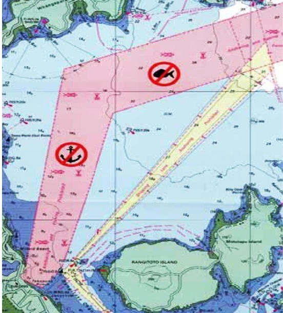
Vessels are not allowed to anchor or fish in this area and the protection zone is constantly monitored from sea or air. Infringement of these rules attracts a fine up to $100,000. Enforcing this rule led to no faults due to human activity.
_____
Maintenance of undersea cables:
For an optimal operation the cable must be periodically checked and maintained in order to prevent deterioration.
This includes:
- Survey of the cable in order to check for possible tears or wears;
- Survey of the cable path in order to check the stability of the seabed and possible geodynamic processes that can threat the cable integrity;
- Preventive replacement of cable components when signs of wear are present or when they are approaching the lifetime end;
- Enforcing rules and regulations regarding the protection in the CPZ.
The operation is performed by specialized vessels with appropriate equipment. It depends heavily on the weather and sea conditions. In high latitude regions where the sea surface is covered with ice or crossed by floating icebergs these operations require additional care measures and lengthy times.
_____
Below several good practices are listed for subsea cable protection that should be taken into account by governments and cable operators.
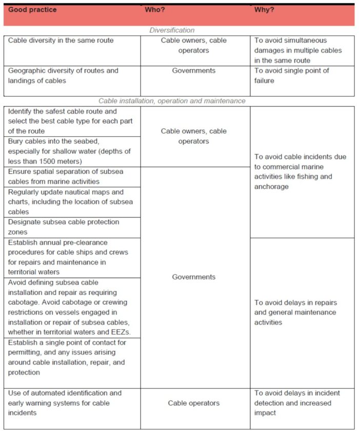
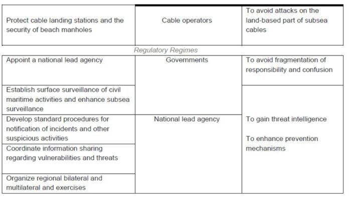
______
______
Section-13
Cable repair:
Submarine cable repair operations represent one of the most critical and technically challenging aspects of maintaining global telecommunications infrastructure. With over 95% of international data traffic passing through undersea fiber optic cables, the ability to quickly and effectively repair damaged cables is essential for maintaining global connectivity, financial systems, military communications, and internet services.
Submarine cable systems, spanning thousands of kilometers across ocean floors at depths reaching up to 8,000 meters, are subject to various forms of damage including fishing activities, ship anchors, seismic events, underwater landslides, and increasingly, potential sabotage. Recent incidents in 2024-2025, including multiple cable cuts in the Baltic Sea and Red Sea, have highlighted the critical importance of robust repair capabilities and rapid response infrastructure.
Cable Statistics:
- 600+ cable systems worldwide
- 1.5 million km of cables
- 95%+ international data traffic
Annual Repair Stats (2024):
- ~200 repairs/year globally
- 86% due to anchors/fishing
- 62 cable repair vessels
_
Modern cable repair typically entails a repair ship that uses a specialized hook to snag a damaged cable from the ocean floor. Once the cable is hooked, it’s slowly pulled up to the surface and onto the deck of the ship. Typically, the damaged portion of the cable is removed and replaced with a new section of spare cable carried on the repair vessel.
The repair process involves sophisticated fault localization techniques, specialized cable ships equipped with remotely operated vehicles (ROVs), precise cable recovery operations using various types of grapnels, and complex jointing procedures that must maintain the cable’s optical and electrical integrity. Modern repair operations can take anywhere from a few days for shallow water faults near repair bases, to several weeks for deep-sea repairs in remote locations or adverse weather conditions.
In 2024-2025, the submarine cable industry faced unprecedented challenges with multiple high-profile cable cuts in the Baltic Sea and Red Sea, some taking up to 5 months to repair. With the global cable network expected to grow 48% by 2040 while nearly 50% of repair vessels approach end-of-life, investment in repair infrastructure and operational excellence has become a critical national security and economic priority for nations worldwide. Meeting the challenges of the rapidly expanding submarine cable ecosystem and an aging cable ship fleet will require an investment of roughly $3 billion to sustain current service levels and avoid repair delays. This would entail the acquisition of 15 replacement ships and five additional ships to serve the global subsea internet infrastructure.
_
Submarine cables represent critical information infrastructure in the global economy. They form the backbone of international telecommunications networks that power global commerce, meeting 95% of all data transmission requirements. With this reliance on submarine cables for connectivity, the infrastructure has been designed to ensure a high level of efficiency. However, cable damage can be unpredictable and unpreventable, and is one of the biggest threats to the health of the global commerce ecosystem. Repairs to cut or severed cables must be carried out quickly, efficiently and cost-effectively to maintain business confidence and reduce disruption.
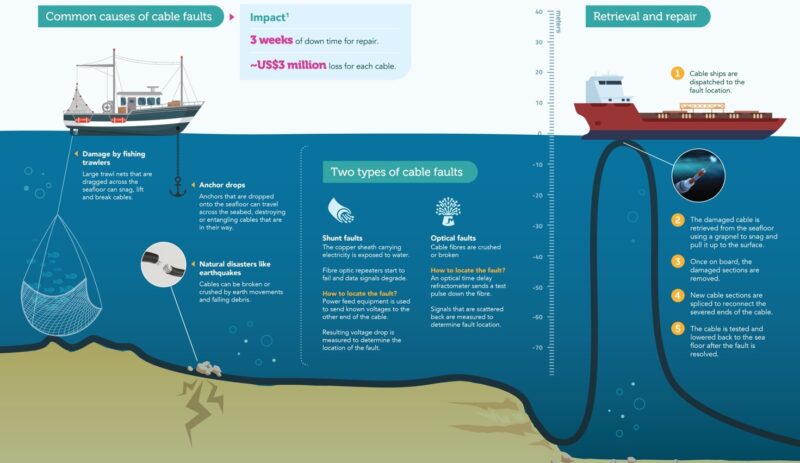
Only few companies in the world are equipped to repair such deep-sea cables. This scarcity of resources means delays are inevitable when multiple disruptions occur. Identifying the exact cause and site of damage is critical but time-consuming, further delaying restoration. Experts also pointed out that fibre cables are vulnerable to natural degradation over time. Such wear and tear make maintenance harder and contributes to the frequency of incidents every five to ten years.
_
Essential points for subsea optical cable repair:
-1. Submarine cable repair operations are critical infrastructure capabilities supporting 95%+ of international data traffic
-2. Three main fault types (shunt, open, break) require different localization and repair approaches
-3. Multiple fault localization techniques (electrical, OTDR, COTDR, electroding) are used in combination for accuracy
-4. Repair durations vary from 3-5 days (shallow, accessible) to weeks (deep sea, remote)
-5. Cable ships and ROVs are highly specialized vessels with precision equipment for depths >2000m
-6. Grapnel recovery requires careful technique to avoid fiber damage during cable retrieval
-7. Fiber splicing and cable jointing take 24+ hours per splice for quality assurance
-8. Regional maintenance agreements provide 24-hour response capability through pre-positioned vessels
-9. 2024-2025 incidents (Baltic Sea, Red Sea) highlight both system resilience and repair infrastructure gaps
-10. Industry faces capacity crisis: 48% cable growth vs. 50% of repair fleet aging out by 2040
________
________
The Repair Process:
It’s a multi-stage operation requiring specialized vessels and skilled technicians. Here’s a breakdown:
-1. Locating the Fault: The first step involves pinpointing the exact location of the cable break. This is typically achieved using Optical Time Domain Reflectometers (OTDRs) which send light pulses down the cable and measure reflections to identify the distance and nature of the fault.
-2. Dispatching the Repair Ship: A specialized cable repair ship, equipped with dynamic positioning systems, remotely operated vehicles (ROVs), and cable handling equipment, is dispatched to the location.
-3. Raising the Cable: The ship uses a grapnel – a large, specialized hook – to snag the cable from the seabed. The grapnel is repeatedly dragged across the area until it hooks the cable.
-4. Cutting and Testing: Once on board, the damaged section of the cable is carefully cut and thoroughly tested to confirm the location and extent of the damage.
-5. Splicing in a New Section: A new section of cable is spliced onto the existing ends. This involves meticulous fiber optic splicing techniques to ensure minimal signal loss.
-6. Testing and Verification: After splicing, the repaired cable is extensively tested to ensure signal integrity and performance.
-7. Lowering the Cable: The repaired cable is carefully lowered back onto the seabed, often with the assistance of an ROV to ensure it is properly positioned and buried (where necessary).
-8. Post-Repair Inspection: The ROV is used to inspect the repaired section and ensure proper burial to prevent future damage.
_
Repairing undersea cables requires a range of specialized equipment:
- Cable Repair Ships: These ships are designed specifically for cable laying and repair, equipped with dynamic positioning, cable tanks, and specialized handling equipment.
- Grapnels: Specialized hooks designed to snag and lift cables from the seabed. Different types of grapnels are used depending on the seabed conditions.
- Remotely Operated Vehicles (ROVs): Underwater robots used for visual inspection, cable burial, and assisting with cable handling.
- Optical Time Domain Reflectometers (OTDRs): Devices used to locate cable faults by analyzing light reflections.
- Splicing Equipment: High-precision tools used to fuse fiber optic cables together with minimal signal loss.
- Dynamic Positioning Systems (DPS): Computer-controlled systems that allow the ship to maintain its position with extreme accuracy, even in rough seas.
______
______
Statistics on Subsea Cable Fault and Repair as of 2025:
Subsea cable fault happens from time to time in the world. On an average, there are approximately 200 faults per year on global subsea cable systems. Fishing and anchoring incidents account for 86% of the subsea cable faults.
According to Global Cable Repair Data Analysis 2024 & 2025, presented at SubOptic 2024 & SubOptic 2025 by Andy Palmer-Felgate, a member of the International Cable Protection Committee (ICPC) and Meta, there are 199 subsea cable faults each year from 2010-2024 on an average. The numbers of faults remain steady from 2013-2024, around 200 faults per year in the world, despite a 50% increase in total in-service cable length from 1.5 million to 2.7 million kilometers in 2025 as seen in figure below. There is remarkable decrease on the fault per year per distance. The achievement is a combination of better geophysical surveys, better armored cables, ability to do deeper burials, better public awareness of where the cables are located, and a higher premium placed in design on reliability.
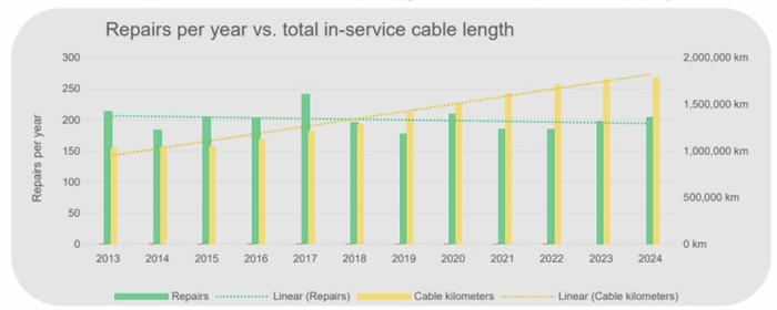
_
According to the ICPC, there were 206 repairs in 2023 in 136 jurisdictions with the longest repair taking 947 days. Analysis data contributions come from all major marine maintenance providers worldwide. The repairs are reported by their locality in a country’s Territorial Waters (TW), Exclusive Economic Zone (EEZ), or on the High Seas. Analysis shows 44% of repairs occurred in TW, 54% in the EEZ, and 2% in the High Seas. Subsea cables are most vulnerable closer to shorelines in shallower waters. Repair response time more than doubled in 10 years for a variety of reasons.
_
Costs and Timeframes: The Economics of Undersea Cable Repair:
It’s an expensive and time-consuming process. Repair operations can cost millions of dollars and take several weeks to complete, depending on the location of the damage, weather conditions, and the availability of repair ships. The cost includes ship charter, fuel, labor, equipment, and cable replacement. The economic impact of a cable outage can be significant, particularly for businesses and industries that rely on high-speed internet connectivity. Subsea cable repairs typically cost between $1 million and $3 million per incident for fiber optic cables, with total expenses often influenced by vessel mobilization fees and repair duration.
_____
_____
Table below shows comparison of Shallow Water vs Deep Sea Repairs:
|
Characteristic |
Shallow Water Repair (<1000m) |
Deep Sea Repair (>1000m) |
|
Typical Duration |
3-7 days |
7-21 days |
|
Cable Recovery |
Relatively straightforward |
Complex, requires careful tension management |
|
Grapnel Type |
Standard cut & hold or holding grapnel |
Specialized deep-sea grapnels |
|
ROV Usage |
Commonly used for location and burial |
Essential for depths >500-1000m |
|
Repair Cable |
May not require repeater addition |
Often requires repeater to compensate loss |
|
Burial Requirement |
Usually required (3m typical) |
Not required in abyssal plains |
|
Weather Sensitivity |
Moderate – can work in rougher seas |
High – requires calm conditions |
|
External Aggression Risk |
High (fishing, anchors) |
Low (component failures primary cause) |
|
Typical Fault Causes |
86% anchor/fishing damage |
Component aging, manufacturing defects |
|
Cable Cut-out Length |
Several hundred meters |
Can be extensive if multiple issues |
______
______
Repair ships:
Shore stations can locate a break in a cable by electrical measurements, such as through spread-spectrum time-domain reflectometry (SSTDR), a type of time-domain reflectometry that can be used in live environments very quickly. Presently, SSTDR can collect a complete data set in 20ms. Spread spectrum signals are sent down the wire and then the reflected signal is observed. It is then correlated with the copy of the sent signal and algorithms are applied to the shape and timing of the signals to locate the break. A cable repair ship will be sent to the location to drop a marker buoy near the break.
_
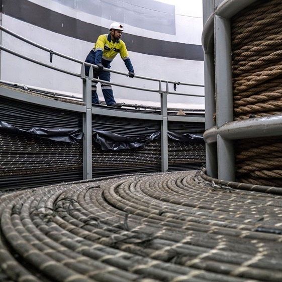
Figure above shows cable spooled aboard the repair ship.
_
If a fault is found, a repair ship is dispatched. All these vessels are strategically placed around the world to be 10-12 days from base to port. You have that time to work out where the fault is, load the cables [and the] repeater bodies – which increase the strength of a signal as it travels along the cables. In essence when you think how big the system is, it’s not long to wait. Modern deep-water repair should take a week or two depending on the location and the weather. When you think about the water depth and where it is, that’s not a bad solution. That does not mean an entire country’s internet is then down for a week. Many nations have more cables and more bandwidth within those cables than the minimum required amount, so that if some are damaged, the others can pick up the slack. This is called redundancy in the system. Because of this redundancy, most of us would never notice if one subsea cable was damaged – perhaps this article would take a second or two longer to load than normal. In extreme events, it can be the only thing keeping a country online. The 2006 magnitude 7 earthquake off the coast of Taiwan, severed dozens of cables in the South China Sea – but a handful remained online.
_
If the faulty part of the cable is less than about 6,500 feet down, the crew will send out a submersible tanklike robot that can move around on the sea floor. A signal can be sent through the cable to guide the robot toward the problem spot. When the robot finds the right place, it grabs hold of the cable, cuts out the nonworking section, and pulls the loose ends back up to the ship.
The robot doesn’t work in very deep water (with very high pressure). In those situations, the technicians aboard the cable ship use a grapnel, or a hook on a very long wire, to snatch up the cable from the sea floor. The grapnel uses a mechanical cutting and gripping device that can split the cable on both sides of the break and drag the loose ends to the surface. One end is hooked onto a buoy so it won’t sink, and the other is hauled on board. The malfunctioning cable section can be fixed on board the ship. A skilled technician or “jointer” splices the glass fibers and uses powerful adhesives to attach the new section of cable to each cut end of the original—a process that can take up to 16 hours. The repaired cable is then lowered back to the seabed on ropes.
_
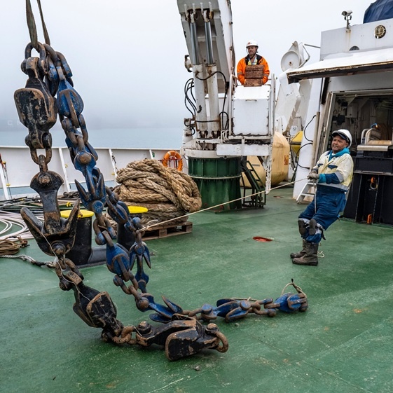
Figure above shows grapnel, used to retrieve cables, on the deck of the Léon Thévenin.
Several types of grapnels are used depending on the situation. If the sea bed in question is sandy, a grapnel with rigid prongs is used to plough under the surface and catch the cable. If the cable is on a rocky sea surface, the grapnel is more flexible, with hooks along its length so that it can adjust to the changing surface. In especially deep water, the cable may not be strong enough to lift as a single unit, so a special grapnel that cuts the cable soon after it has been hooked is used and only one length of cable is brought to the surface at a time, whereupon a new section is spliced in. The repaired cable is longer than the original, so the excess is deliberately laid in a “U” shape on the seabed. A submersible can be used to repair cables that lie in shallower waters.
_
The repaired cables are lowered back into the water, and in shallower waters where there might be more boat traffic, they are buried in trenches. Remotely operated underwater vehicles (ROVs), equipped with high-powered jets, can blast tracks into the seabed for cables to be laid into. In deeper waters, the job is done by ploughs which are equipped with jets and dragged along the seabed by large repair vessels above. Some ploughs weigh more than 50 tonnes, and in extreme environments, bigger equipment is needed – such as one job in the Arctic Ocean which required a ship dragging a 110-tonne plough, capable of burying cables 4m and penetrating the permafrost.
______
______
Current Challenges to cable repair:
The submarine cable maintenance and repair industry faces a severe capacity-and-capability crunch. Globally, as of 2022, around 60 maintenance and repair ships exist for communication cables, a bulk of which are in old condition and close to retirement. The cable repair vessel market has been segmented on grounds of cable-carrying capacity, water depth, and end-use. On the basis of carrying capacity, they are below 1000 tonnes, 1000-3000 tonnes, 3001-5000 tonnes, 5001-7000 tonnes, and above 7000 tonnes. For non-armoured cables the carrying capacity of a cable ship is determined by the metric capacity of its cable tanks.
_
Since, cables can be both, telecom and power cables, the end-user could vary from the offshore oil and gas industry, offshore wind farms, and the telecom sector. Therefore, there is a division of investment in each of these sectors. Moreover, there has been a profound increase in the number communication cable projects without a corresponding increase in a maintenance and repair fleet. New ships require steep investments (above US$ 100-150 million), which are ever increasing due to soaring input costs. Hence, the current practice frequently involves retrofitting ships for the purpose of cable repair. A notable recent example is the acquisition by SB Submarine Systems Company Ltd — a submarine cable installation and maintenance company based out of Shanghai, China of an offshore construction vessel originally built for servicing the oil and gas industry. This vessel was then retrofitted for submarine cable laying and maintenance operations and inducted as the CS Fu Tai within a year — July 2021 (bought) and February 2022 (inducted).
More problematic is the lack of capabilities, i.e., a specialised and trained crew. Lack of awareness about the industry, its small and competitive size, national security concerns, and the time required to train people in cable repair, all contribute to the low recruitment and availability of skilled personnel.
_
Even for ships currently in service, the ownership structure is highly skewed to a handful of private companies.
The following table lists a few repair vessels by ownership, flag state registration, and base port:
Table below shows Global Cable Repair Vessels:
|
Country |
Base Port to Number of Vessels |
Total Number of Vessels Flag-Registered |
Ownership (Number of vessels) |
Other Base Ports (Number of vessels) |
|
France |
4 |
9 |
ASN Marine/Alcatel (4) Orange Marine (4) OMS Group (1) |
Cape Town (1) Cape Verde (1) Worldwide (3) |
|
Marshall Islands |
Nil |
6 |
SubCom LLC (6) |
Baltimore, USA (4) New Caledonia (1) Taiwan (1) |
|
Panama |
Nil |
3 |
S.B. Submarine Systems Co. Ltd (3) |
Wujing Cable Depot, Shanghai, China (3) |
|
Indonesia |
3 |
4 |
OMS Group (3) PT Limin Marine & Offshore (1) |
Batam, Malaysia (1) |
|
Japan |
3 |
4 |
NTT World Engineering Marine (1) KDDI Cableships & Subsea Engineering (3) |
Worldwide (1) |
|
Singapore |
2 |
4 |
ASEAN Cableship Pte Ltd. (3) Global Marine Systems Limited (1) |
Colombo (1) Subic, Philippines (1) |
|
United Arab Emirates |
5 |
5 |
E-Marine |
– |
|
United Kingdom |
3 |
5 |
Global Marine Systems Ltd. |
Curacao (1) Canada (1) |
|
United States |
5 |
1 |
SubCom LLC |
– |
It is, therefore, evident that cable repair ships are concentrated with a few corporations and in a few base ports. We see that France, Japan, the UAE, the USA, and the UK, lead in cable repair capacity globally.
______
______
Innovative Approaches to Subsea Cable Maintenance and Repair:
ROVs and AUVs: These sophisticated machines peer into cables, search for failures, and help their operations in the presence of a human diver. Autonomous Underwater Vehicles (AUVs) are used in cable repair for efficient surveying, inspection, and fault detection of subsea cables, often without requiring a surface vessel. They deploy sensors—like magnetic sensors and cameras—to locate damaged cables, tracking them automatically even at depths over 500 meters. AUVs reduce the cost of routine surveys, typically handling the inspection phase before human divers or ROVs repair the damage.
Predictive A.I. Maintenance: Cable sensors provide a window into the understanding by analysing data for the determination of faults with early intervention before they affect the functioning of the system.
Self-healing Cables: It excels in rerouting data around damaged fibres, thus improving turnaround times before complete repairs are made.
Modular Cable Designs: Simplified structures make on-site faster and cheaper repairs.
Offshore Transmission Conference: Leading the Future of Subsea Cable Management
______
______
Frequently Asked Questions (FAQs):
What happens to the damaged section of the cable after it’s removed?
The damaged section of the cable is brought back to shore for analysis and proper disposal. The materials are often recycled where possible. Analyzing the damage can help identify the cause of the break and improve cable design or installation techniques for the future.
How do repair ships know exactly where to find the cable on the seabed?
Repair ships use a combination of techniques, including GPS, sonar, and historical cable route maps, to pinpoint the approximate location of the cable. They then use grapnels and ROVs to visually locate and recover the cable from the seabed. The OTDR data also helps narrow the search area.
Are undersea cables ever attacked intentionally?
While the vast majority of cable damage is accidental, there have been instances of suspected intentional sabotage. However, such incidents are rare, and proving intent can be difficult. The potential impact of disrupting undersea cables is significant, making them a potential target in times of conflict.
How long does it typically take to repair a damaged undersea cable?
Repair times vary depending on factors such as the location of the damage, weather conditions, and the availability of resources. A typical repair can take several weeks, from the initial fault detection to the complete restoration of service.
How often do undersea cables get damaged?
Undersea cables experience a significant number of breaks each year. Most of these breaks are minor and quickly repaired, but major incidents can cause widespread disruptions. The frequency of damage highlights the importance of proactive maintenance and prevention measures.
What is the lifespan of an undersea cable?
The typical lifespan of an undersea cable is around 25 years. However, with proper maintenance and repairs, cables can often operate for longer. Technological advancements also lead to the replacement of older cables with newer, more efficient ones.
What happens if a cable is damaged in very deep water?
Repairing cables in very deep water presents significant challenges. Specialized ROVs and deep-sea grapnels are required. The time and cost of repairs are significantly higher in deep-water environments.
How does weather affect undersea cable repairs?
Severe weather conditions can significantly hinder or delay repair operations. High winds, rough seas, and poor visibility can make it difficult or impossible for repair ships to operate safely.
Who is responsible for paying for undersea cable repairs?
The cable owners are responsible for the cost of repairs. This is typically a consortium of telecommunications companies and other organizations that have invested in the cable system.
Are there any international laws governing the protection of undersea cables?
Yes, there are several international laws and treaties that aim to protect undersea cables from damage. These laws address issues such as liability for damage, freedom of the seas, and the obligation to avoid causing harm to other users of the ocean.
_______
_______
Section-14
Undersea internet cable ownership:
Undersea cables are built, owned, operated, and maintained primarily by private sector companies. Approximately 98 percent of the world’s undersea cables are manufactured and installed by four private firms in 2021, the U.S. company SubCom, French firm Alcatel Submarine Networks (ASN), and Japanese firm Nippon Electric Company (NEC) collectively held an 87 percent market share, with China’s HMN Technologies, formerly known as Huawei Marine Networks Co., Ltd., holding another 11 percent. Commercial undersea cables can be owned by a single company or a consortium of companies, including telecommunication providers, undersea cable companies, content providers, and cloud computing service providers. Amazon, Google, Meta, and Microsoft now own or lease around half of all undersea bandwidth worldwide. The companies that build and own these cables often lease out bandwidth on their cables through indefeasible rights of use (IRUs), which grant long-term access to a portion of the cable’s capacity. IRU holders can also lease this bandwidth to other third parties, creating a layered leasing market that extends the cable’s reach and utility across various sectors and regions.
_
Historically, there have been two different types of submarine cable system ownership models: consortiums and private.
Consortiums:
Traditionally, submarine cables were owned by telecommunications carriers, who would form a consortium among parties interested in securing capacity on the cable. In turn, these carriers could share the manufacturing/supplier costs, as well as outlays needed to install the submarine cable. For their financial commitment, carriers would be able to use a portion of the underwater internet cable’s capacity.
More recently, cloud service providers (CSPs) and over-the-top (OTT) media service companies, collectively known as hyperscalers, have also become involved in these consortiums.
Private:
Beginning in the mid-to-late 2010s, these hyperscalers also began developing private submarine cables, either independently or with very few owners, as compared to the consortium model. In so doing, these hyperscalers shifted their strategy from solely being buyers of wholesale network capacity, to being owners of that network capacity through subsea cables.
More precisely, hyperscalers including Amazon, Facebook (Meta), Google, and Microsoft have become major investors in new submarine cables due to their need for high-bandwidth, low-latency, and high-redundancy capacity to power their applications.
_
Historically, submarine cables were primarily owned by major telecommunications carriers like AT&T, British Telecom, Orange, and NTT. They built these cables in partnerships, sharing ownership, costs, and capacity.
These days, however, the landscape has shifted dramatically. The rise of cloud computing, streaming video, social media, and massive data centers has put tech giants like Google, Meta (Facebook), Amazon, and Microsoft in the driver’s seat. In fact, as of 2022, more than half of all new submarine cable capacity has been funded directly by these content providers.
Of course, specialized submarine cable operators like SubCom (formerly TE SubCom) and ASN (Alcatel Submarine Networks) still play a critical role. These companies have built a business around manufacturing, deploying, and maintaining cables for others.
Finally, governments occasionally get directly involved—especially when cables are built to connect remote or strategically important regions. These projects might not always be commercially viable, but they are crucial for national development and security.
_
The ecosystem to build, lay, and repair cables is small, consisting of four major manufacturers, and the market for cables today is dominated by a handful of hyperscalers—major tech companies that are driving the expansion of subsea fiber-optic cable networks. The four firms that dominate cable production include SubCom (United States), NEC (Japan), Alcatel Submarine Networks (France), and HMN Tech (China). Hyperscalers—including Google, Meta, Microsoft, and Amazon Web Services (AWS)—are the modern tech giants that provide cloud computing, digital infrastructure, and data processing and storage. These companies are increasingly investing, owning, and operating their own subsea fiber-optic cables or joining consortiums with global telecommunications companies or tech leaders. Collectively, manufacturers and hyperscalers are dependent on access to specialized ships, submersible vehicles that can lay and bury the cables, and the skilled crews and technicians necessary to manufacture, lay, repair, and test the cables. These stakeholders must navigate a complex planning, permitting, and financing environment to support new projects and keep existing cables operational.
______
Key Players of Submarine Optical Fiber Cable Market:
- Fujitsu Limited
- NEC Corporation
- Ciena Corporation
- ABB Ltd.
- SubCom
- Xtera
- Alcatel-Lucent Submarine Networks SAS
- Cable & Wireless Communications Ltd.
- NTT World Engineering Marine Corporation
- S. B. Submarine Systems Co., Ltd.
- Seaborn Networks LLC
______
______
Users of Submarine Cables:
Users of submarine cable capacity are, in many instances, the same cable operators that own the infrastructure. Specifically, significant users of subsea cable capacity include telecommunications carriers, mobile network operators, cloud service providers (CSPs), and over-the-top (OTT) media service companies. In addition, multi-tenant data center operators, financial services companies, government agencies, and large enterprises are also key customers of ocean internet cable owners.
Demand Drivers of Underwater Internet Cables:
Demand for new submarine cables and capacity upgrades are primarily driven by capacity needs, as a result of growing data traffic volumes, and greater connectivity needs. In particular, cloud service providers (CSPs) and over-the-top (OTT) media service companies are driving this growth, as they currently comprise approximately 2/3rds of international internet traffic.
Data is Driving the Infrastructure Need:
Demand for bandwidth is expected to double every two years, over the medium-term. This growth in bandwidth requirements is being driven by an increasing number of users, coupled with greater data consumption per user. More specifically, examples of the applications from cloud service providers and content/OTT media services, that are driving data demand, include:
- Amazon: Amazon Web Services (AWS), Prime Video, Amazon.com (Retail), Kindle, Twitch
- Microsoft: Bing, Azure, Microsoft 365, Microsoft Teams, Dynamics 365, OneDrive, LinkedIn, Skype, Xbox, Outlook.com
- Alphabet: Gmail, Google Drive, Google Maps, Google Photos, Google Play, Search, YouTube, Google Cloud
- Meta Platforms: Facebook, Instagram, Messenger, WhatsApp, Metaverse, Oculus
- Content/OTT: Netflix, Hulu, Disney+, HBO Max, Apple TV+, Paramount+, Peacock, Discovery+
Overall, new submarine cables supply the international bandwidth capacity that is needed, to satisfy the tremendous demand for more data traffic, which is being driven by applications from companies including Amazon, Microsoft, Alphabet, and Meta Platforms.
Route Diversity:
At the same time, route diversity, redundancy, and more direct control over critical infrastructure is driving the need for more submarine cables. Specifically, having bandwidth available on multiple subsea cable systems is important, in order to provide a high level of network availability and reliability.
Demand for route diversity is particularly being driven by the hyperscalers – cloud service providers and OTT media services – who need to control their own infrastructure. Furthermore, these hyperscalers are not necessarily seeking the same routes as telecommunications carriers. For example, in certain instances, hyperscalers are deploying submarine cables for international data center-to-data center connectivity purposes. Indeed, these routes often do not link major international cities together, which has been the traditional focus of carriers.
______
______
The shift from telecom consortia to “content providers”:
Until the late 1990s, nearly every cable was funded by a club of national telecom carriers (often state-owned) that each bought an indefeasible right of use. Over the past decade, hyperscale cloud and social-media companies—Google, Meta, Microsoft, Amazon—have become the biggest investors. They want to link their own data-centre regions, reduce transit costs, and guarantee capacity for video-streaming, cloud services, and AI workloads.
Today these four firms control roughly half of all lit trans-oceanic capacity, while pure government-owned cables make up only about one per cent of total route-kilometres. Most new systems are either:
-1. Private / single-sponsor cables (e.g., Google’s “Equiano” Portugal-to-South Africa route or Microsoft/Meta’s “MAREA” across the Atlantic), or
-2. Hybrid consortia mixing a big tech sponsor with regional carriers and, occasionally, state-backed operators (e.g., “2Africa”, the 45000 km loop around the continent, which includes Meta plus Vodafone, China Mobile, Orange, Telecom Egypt, MTN and others).
_
Table below shows Snapshot of notable systems and stakeholders:
|
Cable |
Length |
Main Route |
Example stakeholders |
|
2Africa |
~45 000 km |
Europe–Africa–Middle East loop |
Meta, Vodafone, China Mobile, MTN, Orange, STC, Telecom Egypt |
|
SEA-ME-WE 5 |
~20 000 km |
Singapore → France |
~ 20 Asian, Middle-Eastern & European carriers |
|
MAREA |
6 600 km |
Virginia → Bilbao |
Microsoft, Meta, operated by Telxius |
|
JUPITER |
14 600 km |
U.S. West Coast → Japan & Philippines |
AWS, Meta, SoftBank, NTT, PCCW, PLDT |
|
PEACE |
15 000–25 000 km |
Singapore → East Africa → Europe |
PEACE Cable International (China) with regional partners |
______
______
Financing:
Deploying and maintaining submarine cables is an expensive undertaking. Since 1990, nearly $48 billion has been invested in submarine cables, with almost half of that focused on the Americas. Submarine cables are a complicated business, with risks not well understood by the average lending institution. These cables are also, of course, hidden from view, challenging normal due diligence. The expense and obscurity of submarine cable have required unique financing models compared to other infrastructure projects.
There are three main financing models. The most common by far is the consortium. This model sees a group of firms interested in capacity along a particular route pool their resources to build the cable, then share capacity. Roughly 90 percent of undersea cable funding in the last three decades has come from consortia, amounting to $43 billion.
Multilateral development banks, such as the World Bank, also fund some submarine projects. These development banks offer lower interest rates, more flexible terms, and are more forgiving in the case of default compared to commercial debt alternatives. Most of the $3.2 billion funded through development banks has been devoted to connecting African nations. Development banks account for about 5 percent of undersea cable financing.
The third financing model is private ownership. Here a private company is able to finance the expense of a cable, either for its own use, or to resell capacity to others. Submarine cables offer tremendous economies of scale, so often it is worth investing in the optical technology to support significantly more capacity than a single firm needs, then reselling that capacity to others. This model has historically seen about 5 percent of investment, but it has grown in recent years. Tech giants—primarily Google, Meta, Amazon, and Microsoft—are investing heavily in subsea cables, with new project investment projected to reach $13 billion between 2025–2027 to meet AI and data center demands.
_
Major suppliers:
The three largest companies offering to build submarine cables are Alcatel Submarine Networks of Alcatel-Lucent, based in France; TE SubCom based in US; and NEC Corporation of Japan. These companies tend to dominate the larger international systems, with SubCom having a sizeable lead in the market in terms of number of systems and miles of fiber laid as seen in figure below.
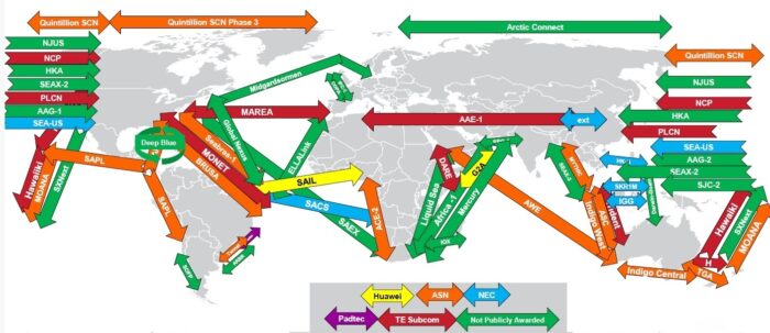
Smaller and mid-size submarine communications companies tend to focus on smaller projects in their own regions, with the exception of Huawei Marine, the fourth-largest provider, which has produced six projects in recent years, mostly in Africa. Many suppliers also participate in projects for offshore oil and gas projects, undersea electrical cables, and other marine infrastructure.
_
China’s rapid emergence as a leading subsea cable provider and owner has been the centrepiece of Beijing’s ambitious Digital Silk Road initiative launched in 2015, which aims to capture 60 percent of the global fiber-optic cable market by targeting emerging economies in Asia, Africa, the Middle East, and the Pacific. While Chinese companies have been recently blocked from subsea cable projects involving U.S. investment and firms due to U.S. concerns about the national security risks that come with HMN Technologies’ unbridled growth, the company has provided 18 percent of the subsea cables (in terms of the total length of cable) that have been laid worldwide over the past four years. HMN Technologies has also become the world’s fastest-growing subsea cable builder over the past 10 years.
_
Cloud Firm Investment:
Google, Facebook, Amazon, and Microsoft now either own or lease more than half the undersea cable capacity. Historically, the vast majority of submarine cables capacity (about 80 percent) was used by Internet backbone and transit providers. However, since 2012, submarine capacity devoted to major cloud service and over-the-top providers has grown significantly. Google, Facebook, Amazon, and Microsoft in particular have begun significant investment in submarine cables since 2016. These four companies now either own or lease more than half the undersea cable capacity.
By recent estimates, Google now has partial ownership of roughly 8.5 percent of submarine cable miles, and sole ownership of roughly 1.4 percent. The longest of Google’s cables is its Curie cable, named after Marie Curie, which runs from Chile to Los Angeles. Google is unique in its private ownership and use of significant amounts of cable, but these tech firms participate in submarine cable consortiums with other companies. Another prominent project is the JUPITER cable from the United States to Asia, constructed in a partnership between Facebook and Amazon. So far, the tech firms are not reselling capacity on cables they have financed themselves. This level of investment has put significant downward pressure on the price of submarine capacity, which continues to decline at about 25 to 28 percent per year.
_
Why tech companies want their own cables:
For years, the subsea cable sector was driven by investments from largely state-owned telecoms operators, but over the past decade tech groups have taken their place. US tech behemoths, including Google, Meta and Microsoft, invested about $2bn in cables between 2016 and 2022, accounting for 15 per cent of the worldwide total. Over the next three years, they will pump in a further $3.9bn, or 35 per cent of the total. These tech groups are also big consumers of cable capacity. According to TeleGeography, they account for two-thirds of bandwidth usage.
Figure below shows Bandwidth (Tbps) used by tech groups and telecoms companies.
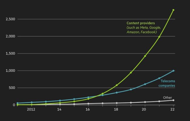
Figure above shows that Meta, Google, Amazon and Facebook account for more than two thirds of undersea bandwidth. Having their own dedicated cables means that they can use them as they like.
According to a 2024 report from the Australian Strategic Policy Institute, Meta, Google, Amazon, and Microsoft control more than 70 percent of the world’s transcontinental cable capacity. This stand is stark contrast to the 10 percent that big tech companies controlled in 2012.
Undersea Cable Infrastructure Ownership:
Google: Part or sole owner of 32 cables
Meta: Part or sole owner of 17 cables; major capacity buyer of 1 cable
Microsoft: Part owner of 4 cables; major capacity buyer of 2 cables
Amazon: Part owner of 2 cables; major capacity buyer of 3 cables
_____
_____
Waterworth:
Meta plans globe-spanning sub-sea internet cable:
Meta has announced plans to build a 50,000km (31,000 mile) sub-sea cable across the world. The tech giant said Project Waterworth – connecting the US, India, South Africa, Brazil and other regions – will be the world’s longest underwater cable project when completed. Meta, which owns Facebook, Instagram and WhatsApp, has sought to extend its presence in technology beyond social media, including in artificial intelligence (AI) and the infrastructure that supports it. It said its new cable project would provide “industry-leading connectivity” to five major continents and help support its AI projects.
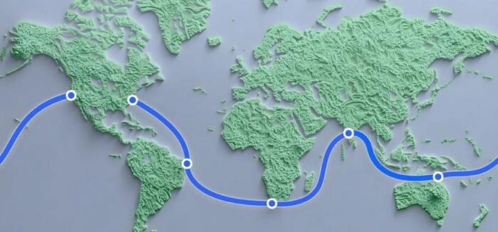
Figure above shows Meta illustration of Project Waterworth showing a thick blue line connecting points in the US, South America, Africa, India and Australia on a global map.
The cable would be the longest to date that uses a 24 fibre-pair system, giving it a higher capacity, according to the firm. The cable bolsters US economic and infrastructural power by improving access to Southern hemisphere markets, supporting South-South connectivity, linking Latin America, Africa, and the Middle East, and helping to boost data traffic between the continents.
Additionally, Waterworth’s route diverges from more established cable corridors. The current longest cable, 2Africa, starts from Europe to circle Africa and the Middle East. Waterworth skips Europe and China to connect the United States directly with major markets in the Southern Hemisphere. Unlike many existing intercontinental cables, Waterworth’s choice of route avoids geopolitical hotspots like the Red Sea and the South China Sea. Damage to Red Sea cables in February 2024 disrupted Internet access for several countries in East Africa. Having a cable which avoids such hotspots can therefore be beneficial for global networks’ resilience. This additional resilience will benefit Meta and potentially also other users leasing cable capacity from Meta through the secondary market.
______
______
Global subsea cable market:
According to a Mordor Intelligence report, the global subsea-cable market is expected to grow from $5.31 Billion in 2025 to $8.95 Billion in 2030 for a CAGR of 11.02 %. That’s mostly due to rising demand for both throughput and redundancy.
Key Takeaways from the Mordor Intelligence Report:
- By component, wet-plant equipment held 53.20% of the submarine optical fiber cable market share in 2024, and auxiliary and marine services are projected to advance at a 12.03% CAGR between 2025-2030.
- By cable type, single-mode fiber accounted for 67.89% of the submarine optical fiber cable market size in 2024, and SDM multi-core fiber is forecast to grow at a 13.89% CAGR through 2030.
- By client type, telecom operators still held a 62.00% market share in 2024 of the submarine optical fiber cable market size, while hyperscale cloud providers are outpacing them at a 12.98% CAGR through 2030.
- By capacity design, systems rated 16-60 Tbps held 56.00% market share in 2024, and above-60 Tbps links are advancing at a 13.70% CAGR through 2030.
- By geography, North America led with a 36.78% revenue share in 2024; the Asia Pacific is poised for the fastest expansion at an 11.56% CAGR through 2030.
______
______
Section-15
Environmental impact of subsea fiber-optic cables:
Generally speaking, the environmental impacts of submarine fiber-optic cables are believed to be modest, although care must be taken during trenching and laying operations. The most significant adverse impacts are most likely to occur during installation when there is increased vessel traffic and disturbance of the seafloor as cable trenches are excavated and the cables are laid. Incorrect cable laying may also lead to significant damage to the marine environment. Furthermore, some submarine power transmission cables may include ducts that contain hydrocarbon-based fluids as a lubricant, coolant, or insulation. Such cables may release these fluids into the environment if damaged, creating environmental risks.
_
Submarine cables have a wide range of potential impacts on the marine environment due to their placement (i.e. cable-laying) as well as due to their operation. The various potential impacts of submarine cables differ considerably in terms of their spatial extent, duration, frequency and reversibility. A general overview of environmental impacts is given in Table below.
|
|
Installation, Maintenance and Repair work, Removal |
Operational phase |
|
Telecommunication cable |
Seabed disturbance Damage/disturbance of organisms Re-suspension of contaminants Visual disturbance Noise (vessels, laying machinery) Emissions and wastes from vessels |
Introduction of artificial hard substrate |
|
Power cable |
Seabed disturbance Damage/disturbance of organisms Re-suspension of contaminants Visual disturbance Noise (vessels, laying machinery) Emissions and wastes from vessels |
Introduction of artificial hard substrate Electromagnetic fields Thermal radiation |
_
The various impacts act on different components of the ecosystem in different ways. Seabed disturbance and thermal radiation may impact benthic organisms, underwater noise is most relevant for marine mammals, electromagnetic fields may have effects on sensitive fish and marine mammals and visual disturbance (including visual and aerial noise) has the potential to displace sensitive sea birds and seals. The extent of such impacts is determined by the technical design of the cables, the laying equipment, and in the case of power cables, the amount of electrical power transmitted. Some environmental impacts are mainly linked to the installation phase and/or maintenance, repair activities and removal. Others are only relevant during operation.
_
Seabed Disturbance:
The laying of cables leads to seabed disturbance and associated impacts of damage, displacement or disturbance of flora and fauna, increased turbidity, release of contaminants and alteration of sediments. Along with noise and visual disturbance, these effects are mainly restricted to the installation, repair works and/or removal phase and are generally temporary. In addition, their spatial extent is limited to the cable corridor (in the order of 10 m width if the cable has been ploughed into the seabed). Such impacts relate to both submarine telecommunications and power cables. Some mobile benthos (for example, crabs) are able to avoid disturbance (Emu Ltd, 2004) and though sessile species (bivalves, tubeworms etc.) will be impacted, the principal risk is in sensitive habitats which include, for example, slower growing vulnerable or fragile species. Avoidance of such areas for cable placement would be an appropriate mitigation measure.
_
Impact on Benthic Communities:
The installation and presence of submarine cables can significantly affect benthic communities – the diverse organisms living on or near the seafloor. During cable laying operations, the direct physical disturbance creates temporary disruption to these habitats, particularly in shallow coastal areas where cables are typically buried to protect them from damage. Research has shown that most impacts are localized and relatively short-term, with many benthic communities showing remarkable resilience. Studies conducted in the North Sea and Pacific Ocean have documented that areas disturbed during cable installation typically recover within 2-3 years, with some fast-growing species recolonizing the affected zones within months.
However, the long-term presence of cables can create what marine biologists call the “reef effect,” where cable structures serve as artificial habitats for various marine species. While this might seem beneficial, it can alter the natural composition of local ecosystems.
_
Reef effect:
The submarine cables themselves, if not buried, will also provide a solid substrate for a variety of species as seen in figure below.
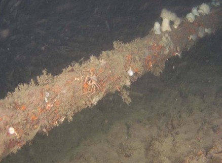
Figure above shows Sub-sea cable, in place for approximately 50 years, covered with sessile encrusting organisms at Vancouver Island (BCTC, 2006). This ‘reef effect’ has been extensively discussed in literature (see for example, Wenner et al., 1983; Reimers & Branden, 1994; Birklund & Petersen, 2004) and essentially leads to the introduction of non-local fauna and thus to an alteration of the natural benthic community. In most cases effects will be localized although long-term. In general, if armouring is required, inert natural stone material should be used to minimise the degree of impact.
_
Noise:
There are no clear indications that underwater noise caused by the installation of sub-sea cables poses a high risk of harming marine fauna. Richardson et al. (1995) provide an overview of investigations into behavioural responses of cetaceans to dredging, an activity emitting comparatively higher underwater noise levels. However, it is not clear if behavioural responses were due to sound or the increased presence of ships. Appropriate scheduling of cable-laying activities will minimise the potential for such impacts on sensitive species (for example, marine mammals or turtles). In addition, performing aerial or other surveys, with suspension of activities if sensitive species are found, are possible mitigation measures.
_
Visual disturbance:
Some sea bird species, for example, divers, are very sensitive to visual disturbance and are displaced by ship traffic (Mendel et al., 2008). It can be expected that the working vessel during the installation process will have the same effect and that these birds will avoid these areas during the cable-laying. Scheduling these activities and/or avoiding of wintering, resting and foraging areas of such sensitive species are possible mitigation measures.
_
Electromagnetic fields:
Electromagnetic fields are generated by operational transmission cables. Electric fields increase in strength as voltage increases and may be as strong as 1000 µV per m (Gill & Taylor, 2001). In addition, induced electric fields are generated by the interaction between the magnetic field around a submarine cable and the ambient saltwater. Magnetic fields are generated by the flow of current and increase in strength as current increases. The strength may reach the multiple of the natural terrestrial magnetic field. In general, HVDC cables produce stronger electromagnetic fields than AC cables. Magnetic fields are best limited by appropriate technical design of the cable (for example, three-phase AC, bipolar HVDC transmission system). Directly generated electric fields are controllable by adequate shielding, however, induced electric fields generated by the magnetic field will occur. Because the strength of both magnetic and electric fields rapidly declines as a function of the distance from the cable, an additional reduction of the exposure of marine species to electromagnetic fields can be achieved by cable burial.
Magnetic fields generated by cables may impair the orientation of fish and marine mammals and affect migratory behaviour. Field studies on fish provided first evidence that operating cables change migration and behaviour of marine animals (Klaustrup, 2006). Marine fish use the earth’s magnetic field and field anomalies for orientation especially when migrating (Fricke, 2000). Elasmobranch fish can detect magnetic fields which are weak compared to the earth’s magnetic field (Poléo et al., 2001; Gill et al., 2005).
Marine teleost (bony) fish show physiological reactions to electric fields at minimum field strengths of 7 mV/m and behavioural responses at 0.5-7.5 V/m (Poléo et al., 2001). Elasmobranchs (sharks and rays) are more than ten-thousand-fold as electrosensitive as the most sensitive teleosts. Gill & Taylor (2001) showed that the dogfish Scyliorhinus canicula avoided electric fields at 10 µV/cm which were the maximum expected to be emitted from 3-core undersea 150kV, 600A AC cables.
_
Thermal radiation:
Thermal radiation from submarine cables has become an issue of increasing concern over the past few years. When electric energy is transported, a certain amount gets lost as heat, leading to an increased temperature of the cable surface and subsequent warming of the surrounding environment. Important factors determining the degree of temperature rise are cable characteristics (type of cable), transmission rate and characteristics of the surrounding environment (thermal conductivity, thermal resistance of the sediment etc.). In general, heat dissipation due to transmission losses can be expected to be more significant for AC cables than for HVDC cables at equal transmission rates.
Published theoretical calculations of the temperature effects of operational buried cables are consistent in their predictions of significant temperature rise of the surrounding sediment. The one field study carried out so far, at the Nysted wind farm, did not provide conclusive results (Meißner et al., 2007). The rise in temperature did not exceed 1.4°C in 20 cm depth above the cable, but the capacity of the cable was only 166 MW. In addition, it was not possible to establish a correlation between temperature increase and power transmitted due to lack of data. Furthermore, the coarse sediment of the study location allowed for increased heat loss through the interstitial water than would be the case in common fine sands or mud.
There is evidence that various marine organisms react sensitively to an even minor increase in the ambient temperature. For example, the recruitment of eastern populations of Atlantic cod (Gadus morhua) decreases with increasing water temperature (Drinkwater, 2004) and the mortality rates of some intertidal gastropods increases due to rising temperatures (Newell, 1979). Nevertheless, field studies on operational submarine cables are almost completely lacking. Preliminary laboratory experiments revealed that the polychaete worm Marenzellaria viridis shows the tendency to avoid areas of the sediment with increased temperature whereas the mud shrimp Corophium volutator does not (Borrmann, 2006). Knowledge of warming effects on bacterial and other microbial activity and, thus on biogeochemical processes is currently insufficient.
Due to the lack of field data, the effects of artificially increased temperature on benthos are difficult to assess. It has to be assumed that a permanent increase of the seabed temperature will lead to changes in physiology, reproduction or mortality of certain benthic species and possibly to subsequent alteration of benthic communities due to emigration or immigration. The temperature increase of the upper layer of the seabed inhabited by the majority of benthos depends, amongst other factors, on the burial depth of the cable. To reduce temperature rise an appropriate burial depth should be applied.
_
Note:
Submarine communication cables do carry 10000 volts in copper sheath to supply power to repeaters; so electromagnetic field and thermal radiation akin to power cable can occur albeit in lesser magnitude.
Benthic organisms, or benthos, are creatures and plants living on, in, or near the bottom of aquatic ecosystems (oceans, lakes, rivers).
______
Assessing the impact of the global subsea telecommunications network on sedimentary organic carbon stocks, a 2023 study:
Marine sediments are the largest store of organic carbon on Earth and this sequestration plays a key role in regulating global climate. However, if previously-buried organic carbon stocks are disturbed and exhumed, this can lead to remineralization of carbon to CO2 (which could potentially increase ocean acidification), limiting the capacity of the ocean to store additional CO2, and potentially adding to the build-up of atmospheric CO2. Sedimentary carbon stocks can be episodically disturbed by natural events, such as floods, storms that resuspend shallow seafloor sediments, or large earthquake-triggered submarine landslides. In addition to these natural events, human activities that impact the ocean floor (e.g. fishing, mining, oil and gas exploration, aggregate extraction, anchoring) are increasingly recognized as playing a significant role in the release of previously-buried organic carbon, with intensity and spatial extent growing by the increased use of marine resources and Blue Growth. It is estimated that 1.3% of the global ocean-floor is trawled each year (∼5 × 10^6 km2), potentially releasing similar quantities of sedimentary organic carbon to agricultural tillage on land. Here, authors assess the potential impact of one of the most extensive infrastructure systems on our planet—the network of subsea telecommunications cables that span more than 1.5 million km across the global ocean. Here, authors present an assessment of organic carbon disturbance related to the globally-extensive subsea telecommunications cable network. Up to 2.82–11.26 Mt of organic carbon worldwide has been disturbed as a result of cable burial, in water depths of up to 2000 m. While orders of magnitude lower than that disturbed by bottom fishing, it is a non-trivial amount that is absent from global budgets.
_______
UNEP-WCMC and ICPC (2025). Submarine cables and marine biodiversity:
A new UNEP-WCMC 2025 report examines the potential pressures, impacts and opportunities of submarine telecommunications cables on marine biodiversity. Overall, the analysis found that submarine cables have a relatively small footprint in the marine environment. Globally, less than 0.01 per cent of the seafloor is within 10 metres of submarine cables. The analysis found that potential pressures and resultant impacts from cable activities on marine biodiversity are generally local and minimal, although they do vary spatially and over the cable lifecycle. The evidence indicates that the primary impact of submarine cables is habitat disruption during installation. This disruption is typically small in scale, short-lived, and has minimal long-term effects on biodiversity. However, for sensitive habitats such as coral reefs and seagrasses, the impacts can vary, with the potential for damage depending on local conditions. The intensity of pressure is highest during installation in shallow waters since cables often need to be buried at these depths for their own protection. Burial techniques can result in physical damage and turbidity. The cables are chemically inert, and once in place they require little to no intervention unless damaged, which is rare. As a result, impacts during the operational phase are typically minimal. The decommissioning and recovery phases are also explored, highlighting the trade-offs between removing out-of-service cables, which will often have an environmental impact, and leaving them in place.
______
Carbon footprint:
Although cables sit on the seabed, multiple peer-reviewed studies show that their environmental impact is relatively benign compared to other infrastructures. Emissions are generated not from the seabed itself but from the manufacturing and maintenance processes, such as where the steel is sourced or how often ships must repair damaged cables. The direct ecological footprint is small, but improving sustainability in production and operations offers real opportunities for reducing the overall impact. And submarine cables do not pollute: they are stable, inert structures that can even be recovered and recycled after they’ve served their time (about 20-40 years, on average). The carbon footprint is actually relatively low compared to most of the internet’s infrastructure.
______
______
Possible mitigation measures to minimise or avoid environmental impacts of various anthropogenic pressures due to cable laying and operation:
|
|
Mitigation Measures |
|
|
|||
|
Environmental impacts |
Route selection |
Construction times |
Burial technique |
Burial depth |
Cable type |
Removal |
|
Disturbance |
x |
x |
x |
(x) |
(x) |
* |
|
Noise |
(x) |
(x) |
(x) |
* |
* |
* |
|
Heat emission |
(x) |
* |
* |
x |
x |
* |
|
Electromagnetic fields |
* |
* |
* |
x |
x |
* |
|
Contamination |
x |
* |
(x) |
(x) |
x |
x |
|
Cumulative effects* |
x |
x |
x |
x |
x |
* |
x: important measure; (x) less important measure; * knowledge insufficient
_
Cable laying and repair activities can have an environmental impact on the marine ecosystem. It’s crucial to minimize this impact by:
- Conducting thorough environmental impact assessments before cable laying and repair.
- Using environmentally friendly cable materials.
- Minimizing disturbance to the seabed during cable burial and repair.
- Avoiding sensitive marine habitats, such as coral reefs and marine protected areas.
- Properly disposing of damaged cable sections.
______
______
Section-16
Geopolitics of undersea internet cable:
Tsuruoka (2018) has called undersea communications cables the Achilles’ heel in a coming new cold war. He rightly notes three important facts about threats and vulnerability: 1) a foe’s hostile act on undersea cables could blind a country’s military, diplomatic, and economic communications; 2) the weapons for such acts will include submarines, underwater drones, robots, specialized ships, and divers; and 3) China, Russia, the United States, and others are focusing on “these deep-sea information pipes as rich sources of intelligence as well as targets in war.” Undersea cables are critical to global communications infrastructure, supporting everything from financial transactions to national security communications, making them a prime target in the escalating great power competition between the U.S., China, and Russia, as well as for other state and non-state actors. Protection of this undersea critical infrastructure will be paramount in future conflicts.
_
The strategic significance of submarine cables extends beyond mere connectivity. They play a pivotal role in shaping economic dependencies and can be leveraged as strategic assets by global powers. The control and ownership of these cables can influence international relations and geopolitical dynamics. For example, the ongoing U.S.-China tech rivalry is evident in the competition over cable infrastructure, reflecting broader tensions in the global arena. This rivalry is not just about technological supremacy but also about securing influence over critical communication routes. Countries are increasingly recognizing the importance of these cables in maintaining their national security and economic interests. As such, the geopolitical landscape surrounding submarine cables is complex and multifaceted, involving a mix of cooperation and competition among nations.
_
Undersea communications cable infrastructure (UCCI) threats:
There are two general categories of threats that may affect UCCI: physical and cyber. The threat actor typology developed by Khalizad (1999, 407) for information-warfare takes account of both, as does the modified threat actor typology for cyberspace put forth by RAND Europe (Robinson et al. 2012, 6). In its analysis of UCCI, the United States Office of the Director of National Intelligence (2017, 9-10) categorized threats as natural, accidental, and malicious, in accordance with DHS guidelines. None of the threats under the categories of natural or accidental would warrant a threat statement—they would be operator responsibility. The malicious category however includes cyber-attack, vandalism, activism, theft, terrorists, and state-actors. Of these, threat statements could easily apply to cyber-attack, terrorists, and state-actors.
When it comes to state-actors, the threat actor typology tells us that rogue states and peer-competitors may have various goals for aggression, anything from defeating a country in confrontation to economic advantage. They may use cyber or kinetic means to achieve these goals. Such means may be carried out by insider or outsider actions. For the analysis of outsider threat actions by regional state-actors, there are three facets of UCCI’s physical facilities that require consideration: the undersea cable, cable landing stations, and networked facility equipment. Undersea cables are submerged and aggression will therefore occur underwater; cable landing stations and network operations centers are above ground facilities that are susceptible to armed assault and aerial strikes; and networked facility equipment is a prime target for cyber-attack. The following are reasonable, though general, threat statements regarding these facets:
(1) Cutting or tapping of undersea communications cables via submarine, submersible vehicle, surface ship, or human diver. The cutting of cables can be performed on a single cable or multiple cables in a chokepoint with cables damaged by dissection in one or more locations or damaged by explosives along a length of cable. The tapping of a cable through technological means to siphon data can occur along any length of the cable.
(2) Cable landing station sabotage or destruction by a violent and determined adversary via aerial attack or armed assault using land-based or water-based transportation.
(3) Cyber-attack on plant facilities including power feeding equipment, submarine line terminating equipment, and network equipment.
_
Table below shows cable vulnerability:
|
Layer |
Exploitable Weakness |
Mitigation Status |
|
Physical cable trunk (deep ocean) |
Reachable by deep-diving manned or unmanned subs with manipulator arms; potential for stealth taps or explosive sabotage |
Only a handful of navies possess such craft; hard to monitor continuously |
|
Shallow-water approaches & landing zones |
Easily snagged by anchors or trawlers; near-shore cuts can take several days to repair |
Burying and armouring helps but cannot stop deliberate acts; AIS-based vessel monitoring is improving |
|
Landing stations & network management systems |
Cyber intrusion or insider compromise could allow traffic interception, route manipulation, or shut-down commands |
End-to-end encryption now widely deployed; zero-trust architecture and physical security tightening |
|
Chokepoints (e.g., Suez, Malacca, English Channel, Luzon Strait) |
Multiple cables run in the same narrow corridor—single event can down several routes |
Pressure to diversify with “long way round” Arctic or South-Atlantic paths |
______
Around the world, the geopolitics of undersea cables is playing out in three distinct arenas.
-1. The first arena involves Washington’s techno-diplomacy offensive against HMN Technologies (HMN or HMN Tech), which is majority-owned by China’s Hengtong group (Hengtong). The previous owner was the marine division of Huawei Technologies Co., the world’s largest telecommunications equipment manufacturer and the ongoing target of US export controls and sanctions.
Since 2019, when Huawei was placed on the US Bureau of Industry and Security (BIS) Entity List, Washington has mounted a three-front war against China’s national champion technology company: on the 5G infrastructure front, where US officials have attempted to persuade governments to block Huawei equipment from their networks; the semiconductor front, where critical microchip technologies have been choked off; and, finally, the subsea cables front.
As background, in early 2020, Huawei Marine Networks Co. was acquired by Hengtong Group, a Chinese state-backed optic cable manufacturer, at which time it took on its new name. Despite the name change, however, HMN has been singled out and effectively decoupled from Western-influenced undersea projects.
To get foreign governments and national telecoms to reject Chinese undersea cable partners, Washington has stepped up the use of financial incentives and the application of pressure on subsea cable consortium members, including threats of sanctions and export controls. The narrative behind these actions is straightforward: If you choose HMN as a consortium partner, you choose a proxy of the Chinese Communist Party (CCP) and give Beijing eavesdropping access to all the data pulsing through your undersea cable network. But US efforts to exclude Chinese companies from the world’s internet backbone are mired in difficulties. Even as the US administration wages its fibreoptic war against Beijing, vessels owned and manned by China are still undertaking complex repair work on US-owned fibre lines.
-2. The second arena involves the emergence of tech titans as major players in the subsea cable economy. Amazon, Google, Meta, and Microsoft have been behind the rapid expansion of undersea cable networks. These firms have deep pockets and move quickly when it comes to funding new projects, but they are geopolitically agnostic when it comes to choosing partners, which sometimes puts them at odds with Washington. The American tech titans are first movers not only in funding more cable gateways, but they are also pushing the innovation envelope in cable technology. This has placed them in a grey zone, where Washington views them as strategic partners when it comes to playing for the home team, but as security risks when they team up with the wrong consortium partners. Beyond the geopolitical realm, Big Tech now faces increased scrutiny under antitrust laws, as they exercise control over bandwidth in their cable networks, which they increasingly rent out to telecommunications carriers and other third parties.
-3. The third arena is perhaps the most worrisome: sabotage and outright attacks on undersea cables by adversaries. Recent events in the Baltic Sea and the Taiwan Strait involving the cutting and disabling of undersea cables reveal their vulnerabilities. These events have been linked to escalation of hostilities between Russia and the North American Treaty Organization (NATO) and the rising tensions between China and Taiwan.
_____
Contemporary Geopolitical Risks:
US–China technology rivalry:
- Cabling influence: Washington now pressures allies to bar Chinese suppliers (e.g., ex-Huawei Marine) from cable builds and landing licences, citing espionage concerns.
- Blocked projects: The Pacific Light Cable Network’s planned Hong Kong landing was vetoed by U.S. regulators in 2020; the cable was rerouted to Taiwan and the Philippines.
- Digital bifurcation: Competing Chinese- and US-backed consortia are racing to build parallel Asia–Africa–Europe routes, each trying to keep key landing stations inside friendly territory.
Russia versus NATO/allies:
- Russian “oceanographic” ships and deep-submergence vessels regularly patrol over Atlantic and North-Sea cable corridors, mapping routes and—Western militaries fear—pre-positioning for disruption.
- NATO now treats critical seabed infrastructure security as a collective-defence matter. A specialist maritime centre was launched in 2023; the UK and France have commissioned dedicated seabed-monitor vessels and under-ice drones.
- Hybrid tactics: dragging trawler nets or anchors to create “accidental” breaks can produce economic disruption while retaining plausible deniability.
_
Geopolitical threats:
In recent years, Western policymakers have become particularly concerned about the capabilities of Russia and China to exploit the vulnerabilities of undersea cables. One particularly illustrative incident occurred in 2023 when Taiwanese authorities accused two Chinese vessels of cutting the only two subsea cables supplying internet to Taiwan’s Matsu Islands. The resulting digital isolation of 14,000 residents for six weeks was not an one-off episode. Taiwan’s ruling Democratic Progressive Party has pointed to a pattern, noting that Chinese vessels have disrupted cable operations on 27 occasions since 2018. Beijing and its media mouthpieces have pivoted from denial to disinformation, suggesting that Taiwan is orchestrating these disruptions to stoke international sympathy or escalate tensions. In January 2025, Taiwan’s coast guard blamed a Cameroon- and Tanzania-flagged vessel crewed by seven Chinese nationals and operated by a Hong Kong-based company when an undersea cable was severed off the island’s northeastern coast. Such incidents, often described as grey-zone aggression, are designed to wear down an adversary’s resilience and test the limits of response. China’s recent push to enhance its cable-cutting capabilities coincides with a surge in its military drills around Taiwan, including a number of recent exercises.
Similar cable disruptions have occurred in the Baltic Sea. In October 2023, a telecom cable connecting Sweden and Estonia was damaged along with a gas pipeline. In January 2025, a cable linking Latvia and Sweden was breached, triggering NATO patrols and a Swedish seizure of a vessel suspected of sabotage tied to Russian activities. Dmitry Medvedev, deputy chairman of Russia’s Security Council, even hinted at the possibility of targeting undersea communication cables as retaliation for actions such as the Nord Stream pipeline explosions in 2023.
The involvement of state-linked vessels in incidents operating under flags of convenience − that is, registered to another country − further complicates efforts to attribute and deter such attacks.
It isn’t just security and defense at risk. The modern financial system is predicated on the assumption of continuous, high-speed connectivity; any interruption, however brief, could disrupt markets, halt trading and lead to significant monetary losses.
______
Russian navy could target Undersea Internet Cables:
The Russian Navy has unique undersea warfare capabilities designed to operate on undersea cables.
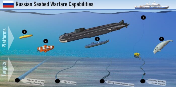
Russian seabed warfare capabilities (figure above) can target underwater infrastructure including internet communications. Platforms include 1) Large host submarines which deploy deep-diving nuclear-powered submersibles. 2) The special intelligence ship Yantar which can deploy remote operated vehicles (ROVs) and crewed submersibles. 3) Autonomous underwater vehicles (AUVs). 4) Dual-use crewed submersibles such as rescue submarines which can also work on cables. 5) trained Beluga whales and possibly seals or dolphins.
Among the various possible scenarios threatening European and Euro-Atlantic security, Western experts consider, among others, the damage or destruction by special Russian submarines of the communication cables linking the island of Great Britain with continental Europe and the US and Europe. Such cables in general provide most of the internet connectivity, and their damage could not only adversely affect the state of intercontinental connectivity, but also worsen the geopolitical situation globally.
_
The idea that the global internet could plunge into darkness because of damage to some cables is frightening. US Navy officials have warned for years that it would be catastrophic to be attacked by Russia, which has repeatedly been caught tracking nearby cables. As recently as in 2018 the UK’s most senior military officer stressed that cutting undersea cables would lead to an “immediate and potentially catastrophic” economic impact, especially as Russian vessels have been spotted in the Atlantic Ocean at locations for intercontinental cable laying (Matsakis, 2018).
There are several possible objectives that cutting the cable can achieve: cutting off military or government communications in the early stages of a conflict, eliminating internet access to a target population, sabotaging an economic competitor or causing economic disruption for geopolitical reasons. Actors may also pursue several or all of these objectives simultaneously.
______
China’s new underwater tool cuts deep, exposing vulnerability of vital network of subsea cables:
Chinese researchers have unveiled a new deep-sea tool capable of cutting through the world’s most secure subsea cables − and it has many in the West feeling a little jittery. The development, first revealed in February 2025 in the Chinese-language journal Mechanical Engineering, was touted as a tool for civilian salvage and seabed mining. But the ability to sever communications lines 13,000 feet (4,000 meters) below the sea’s surface − far beyond the operational range of most existing infrastructure − means that the tool can be used for other purposes with far-reaching implications for global communications and security. The growing sophistication and openness of underwater technology evidenced by the latest news from China suggest that undersea infrastructure may play a larger role in future strategic competition. Indeed, this development adds a new layer to the broader challenge of securing critical infrastructure amid expanding technological reach and the rise of so called “grey zone” tactics – antagonisms that take place between direct war and peace.
_____
_____
China’s submarine cable power play in MENA:
The Middle East and North Africa (MENA) have become increasingly connected to submarine cable networks owned, built, or upgraded by Chinese firms. Since they entered the market in the late ‘90s, Chinese companies have constructed, upgraded, or acquired ownership stakes in thirteen of some sixty-two cables traversing MENA, forging fifty-seven connections at thirty-nine landing stations. In 2025, another (SeaMeWe-6) went online, raising the total to sixty-one connections at thirty-nine MENA landing stations. Submarine cables are among the most critical digital infrastructures, serving as conduits for more than 95 percent of international data flows and communications, including an estimated $10 trillion in financial transfers daily. With China aiming to capture 60 percent of the cable market by 2025, MENA could become increasingly reliant on Chinese networks to transmit sensitive data.
_
MENA countries have welcomed these connections as a means to diversify their networks— reducing dependence on US/Western cables. As home to one of three critical cable choke points—the Suez Canal-Red Sea-Mandab Strait passage—the Middle East and North Africa region is of geostrategic significance to China. These cables form part of the Digital Silk Road and connect China’s transregional assets (military and civilian), along the Belt and Road Initiative (BRI). Ensuring highspeed, low-latency connectivity is vital in optimizing and maintaining the integrity of supply chains and other activity that supports economic growth. Chinese energy imports from MENA, and much of its trade from the region and Europe, travel through the Suez Canal Red Sea-Mandab Strait passage. The Pakistan and East Africa Connecting Europe (PEACE) fiber-optic cable, a network funded, owned, and constructed entirely by Chinese entities, was built specifically to complement the BRI. It connects Chinese assets (the $62 billion infrastructure project known as the China Pakistan Economic Corridor) in Gwadar, Pakistan, to Djibouti, which hosts a Chinese naval base, and runs through the Middle East and onward to Europe. PEACE would harbor immense strategic significance for China even if it were not commercially viable because it supports and enhances the People’s Liberation Army’s ability to project power.
_
China wants to reduce its dependence on foreign cables while making other countries more dependent on Chinese networks. China’s growing presence in MENA’s cable industry is significant because Beijing has the power to shape the route of global internet traffic by determining when, where, and how to build cables. For a country that seeks to alter the internet’s physical form and influence digital behavior while exerting supreme control over information flows, the dominance of the undersea cable network provides significant strategic advantages. Until now, the issue of who controls 5G in MENA has overshadowed other information and other technologies, with ports sometimes added to the mix. However, considering the US strategic reorientation to increase its engagement with the Middle East to counter China, particularly in advanced technology, MENA’s subsea cables are poised to attract more attention. PEACE, in particular, is poised to emerge as a flashpoint in the Sino-American internet feud.
_____
_____
How China controls undersea cables and data flows:
-1. Cable Routing Protocols:
The rapid construction of undersea cables has brought a hidden but crucial issue into focus: the manipulation of the protocols that control how data travels beneath the sea. These protocols determine the pathways internet data takes, influencing speed, costs, and even exposure to surveillance. Even small changes in these pathways can tilt the global balance of digital power. China’s increasing role in this area demonstrates how technology can be used strategically to reshape geopolitics.
At the heart of this issue is a technology called Software-Defined Networking (SDN). SDN allows data traffic to be managed and optimized in real time, improving efficiency. But this same flexibility makes SDN vulnerable to misuse. Chinese tech companies like HMN Tech (formerly Huawei Marine Networks), ZTE, and China Unicom are leading the way in SDN development. China also holds sway in international organizations that set the rules for these technologies, such as the International Telecommunication Union (ITU) and the Institute of Electrical and Electronics Engineers (IEEE). This influence gives China a hand in shaping global standards and governance.
Africa illustrates how this influence plays out. Chinese investments in digital infrastructure across the continent are massive. For example, the PEACE (Pakistan and East Africa Connecting Europe) cable, which links East Africa to Europe, was designed to avoid Chinese territory. Yet, thanks to SDN technology, its traffic can still be redirected through Chinese-controlled points. This redirection could introduce delays of 20 to 30 milliseconds per hop—not much for casual browsing, but a serious issue for latency-sensitive activities like financial trading or encrypted communication.
_
-2. Fiber-Optic Cable Repair Networks
China’s disproportionate control over fiber-optic cable repair networks reveals potential vectors for intelligence dominance, coercive leverage, and disruption of digital sovereignty. Globally, an estimated 60 dedicated cable repair ships service the planet’s 1.5 million kilometers of submarine cables. China controls a substantial percentage of the fleet, including ships operated by state-affiliated enterprises like Shanghai Salvage Company and China Communications Construction Group. In contrast, the United States and its allies maintain a small patchwork fleet, mostly concentrated in the North Atlantic and lacking coverage in the Indo-Pacific, where over 50% of global internet traffic routes through key subsea cables.
Repair missions involve exposing critical cable infrastructure, including repeaters, amplifiers, and branch units—hardware that boosts signal strength over long distances but also represents points of vulnerability. Chinese vessels are equipped with advanced robotic submersibles and precision cutting-and-splicing technologies, designed for repairs but capable of installing signal interception devices. Such tools could include optical fiber taps capable of harvesting unencrypted metadata or capturing latency patterns to infer sensitive traffic flow. China’s advancements in photonics and quantum communication technologies underscore its capacity to exploit these vulnerabilities. The Chinese Academy of Sciences has reported significant breakthroughs in quantum key distribution (QKD) systems, raising the possibility of developing quantum-based methods to crack encrypted data intercepted during repairs. Integration of AI-driven data sorting tools could automate the extraction and classification of intercepted information, rendering bulk data acquisition during repairs a strategic advantage.
_
-3. Maritime Data Through Automated Vessel Tracking
China’s exploitation of automated vessel tracking systems exemplifies a sophisticated component of its global digital strategy. At the heart of this initiative lies the Automatic Identification System (AIS), a maritime safety technology mandated by the International Maritime Organization (IMO) for vessels exceeding 300 gross tons engaged in international trade. While originally intended to improve navigational safety by broadcasting vessel identities, locations, courses, and cargo details, AIS has been effectively repurposed by Beijing into a dual-use asset that supports both economic intelligence gathering and military surveillance.
Chinese firms, including the BeiDou Navigation Satellite System and Alibaba Cloud, have developed advanced platforms that aggregate AIS transmissions from shipping lanes worldwide. These platforms integrate AIS data with artificial intelligence-driven predictive analytics, enabling Beijing to monitor and analyze global maritime chokepoints such as the Strait of Malacca, the Panama Canal, and the Suez Canal—key arteries of international commerce. By doing so, China gains critical insights into global shipping patterns, strategic trade routes, and supply chain dynamics. As of 2023, the global merchant fleet comprised around 60,000 ships.
During the 2021 Suez Canal blockage, Chinese logistics firms, leveraging real-time AIS data, rapidly identified alternative routes through the Arctic and along the Indian Ocean, allowing Chinese exporters to reroute goods while Western competitors faced delays. Similarly, in the Strait of Malacca, a waterway facilitating the transit of over 16 million barrels of oil daily and 40% of global trade, Chinese analysts have used AIS data to optimize resource flow, pre-empt congestion, and study vulnerabilities in energy supply routes.
______
______
Section-17
Cyberattacks on subsea internet cable system:
Global internet and telecommunications traffic is routed and transported through the undersea telecommunication cable network using advanced information and communication technologies and network management software, making the system vulnerable to cyberattacks. A 2021 think tank report notes that, “more companies are using remote management systems for submarine cable networks—tools to remotely monitor and control cable systems over the Internet—which are cost-compelling because they virtualize and possibly automate the monitoring of cable functionality.” However, these tools (e.g., software, remote management systems) may create new risks to cable security and resilience. Hackers could access cables through network management systems to skim personal or financial information, hold network management systems hostage until operators pay ransom, or cause widespread disruption in communications.
_
In April 2022, U.S. Department of Homeland Security Investigations (DHSI) reportedly thwarted a cyberattack on a network of a company that manages an undersea telecommunication cable that provides internet and mobile phone services in Hawaii and in countries across the Pacific region. DHSI officials attributed the attack to an international hacking group, but were not certain of the intent—whether the attacker intended to access business or personal information, hold the system for ransom, or to disrupt communications. DHSI reportedly worked with law enforcement agencies in several countries to make an arrest.
_
Tapping undersea cables for espionage is not a new idea. Back in the 1970s, submarines were sent on missions like Operation Ivy Bells. Troops were sent down to the bottom of the Sea of Okhotsk in Soviet territorial waters to find a five-inch diameter cable that carried communications between military bases. They installed a 20-foot long listening device on the cable to record Soviet messages. The tap was eventually discovered, and that specific mission had been compromised. Such operations could still be ongoing beneath the ocean without us knowing. However, with tech giants quickly gaining control of more and more cables, there could be a new way to spy on other countries. Partnerships or deals with these companies can easily give governments access to the information that flows through the cables.
_
Cyber attackers don’t always need to physically cut cables. They use advanced persistent threats (APTs) to exploit:
- Shore-based landing stations
- Network monitoring and traffic metadata
- Data routing manipulations via BGP hijacking
- Firmware backdoors in cable amplifiers or routers
A single breach at a cable’s terrestrial endpoint could allow adversaries to tap into data, inject malware, or reroute traffic to surveillance nodes. State-backed actors like APT groups or military cyber units view them as high-value targets. Damaging or tapping into these cables can cripple economies, disrupt military operations, or result in espionage gains.
______
______
Tapping Fiber Optic Cables:
Fiber optic cables present a different set of challenges for interception due to their operational principles. Data is transmitted as light, making traditional electrical tapping methods ineffective. Instead, sophisticated optical techniques are required.
Micro-bending and Side-channel Tapping:
One of the most insidious methods for tapping fiber optic cables involves inducing a “micro-bend” in the fiber. By subtly deforming the cable, a minute amount of light can “leak” out of the core of the fiber. This leaked light can then be detected by a sensitive optical sensor positioned nearby. This method is highly covert as it does not require breaking the fiber and can be done without interrupting the data flow, making it exceptionally difficult to detect in real-time. The slight attenuation in the signal might go unnoticed amidst the noise and typical operational variations.
Cladding Power Extraction:
Another sophisticated technique involves extracting power from the cladding of the fiber. While the data travels in the core, a small amount of light can propagate in the cladding. By carefully manipulating the fiber’s external layers, an interceptor might be able to couple to this cladding light and glean information, albeit often with lower data rates and higher error rates compared to direct core tapping. This method also benefits from being non-invasive to the main data path.
Dark Fiber Interception:
In some instances, “dark fiber”—unused fiber optic strands within a cable—might be targeted. If an organization has laid a cable with multiple unused fibers, an adversary could potentially gain access to these strands and activate them for their own uses, or even use them as a “backdoor” to access active fibers within the same cable sheath through cross-talk or other advanced techniques. This highlights the importance of not only securing active cables but also considering the potential vulnerabilities of unused infrastructure.
Optical Splitting:
It is also possible to insert a splitter between two cut parts of a fiber, with the apparent result of easily diverting a part of the traffic to a second fiber or a storage device. Although this method has the drawback of briefly interrupting the signal, if the operation is conducted efficiently the interruption can be reduced to a short span of time. In a section of the cable with high optical power this method will generate a minimal loss of signal, but powered lossless splitters can be installed to balance the signal deterioration.
Passive Tapping:
Passive optical tapping involves stacking polydimethylsiloxane (PDMS) layers as planar waveguides for light transmission and capture. These added layers act as optical sniffers, intercepting data from input optical fibers while maintaining transparency to the transmitter. The stackable and removable waveguides offer a dynamic solution.
____
Deployment Platforms and Operations:
Once a target location is identified, the deployment of tapping devices requires specialized underwater vehicles and highly skilled operators. The choice of platform depends on depth, secrecy requirements, and the specific tapping method.
Submarines:
Naval submarines, particularly those designed for special operations, are ideal platforms for covert undersea cable tapping. Their stealth capabilities allow them to approach target areas unnoticed. They can deploy specialized submersibles or remotely operated vehicles (ROVs) to perform the actual tapping operation. Submariners are trained in precision navigation and complex underwater maneuvers, making them perfectly suited for such delicate tasks.
Unmanned Underwater Vehicles (UUVs):
Advanced UUVs are emerging as increasingly capable platforms for undersea missions, including cable tapping. These autonomous vehicles can operate for extended periods, reducing the risk to human operators. They can carry sophisticated sensors and manipulators to locate, access, and attach tapping devices to cables. Their smaller size and lower acoustic signature make them harder to detect than manned submarines.
Civilian Cover Operations:
In some cases, tapping operations might be conducted under the guise of legitimate marine research, cable repair, or survey activities. Commercial vessels equipped with specialized diving capabilities or ROVs could potentially be used to deploy tapping devices, blurring the lines between legitimate and illicit activities. This makes attribution incredibly difficult.
______
______
Cyber espionage and Intelligence-gathering:
Submarine cable cyber espionage involves state-sponsored actors tapping, disrupting, or monitoring the ~900,000 miles of undersea cables that carry 95% of international data, transforming them into tools for mass surveillance and strategic intelligence. Vulnerabilities lie in shallow-water tampering, compromised landing stations, and maintenance vessel monitoring, with increasing risks from countries like China and Russia in the Indo-Pacific and Baltic regions. The rising sophistication of cyberattacks underscores the vulnerability of submarine cables to cyberespionage, ultimately complicating their security. Techniques like cable tapping, hacking into network management systems, and targeting cable landing stations enable covert data access by intelligence agencies, with Russia, the U.S., and the United Kingdom (U.K.) noted as primary players. These activities are driven by both strategic and economic motives, with advancements in technology making interception and data manipulation more effective and difficult to detect. Recent technological advancements increasing the vulnerability include the use of remote access portals and remote network management systems centralizing control over components, enabling attackers to monitor traffic and potentially disrupt data flows.
______
______
Cyber Security Countermeasures:
Increasingly, sophisticated cyber-attacks threaten the data traffic on the cables, with incentives ranging from financial gain, espionage, or extortion by either state actors or non-state actors. Further, hybrid warfare tactics can interfere with or even weaponize the data transferred by the cables. However, attributing an incident to a specific actor or motivation of such actor can be challenging, specifically in cyberspace.
Cyber-security strategies for submarine cables, such as encryption, access controls, and continuous monitoring, primarily focus on preventing unauthorized data access but do not adequately address the physical protection of cables in vulnerable, remote, high-sea areas. As a result, while cybersecurity protocols are effective near coastal landing points, their enforcement across vast stretches of the open ocean becomes a challenge.
Physical security remains important. Typically, cables are buried in waters with a depth of less than 2,000 meters. Increasingly, they are also being buried in the deeper seabed to protect against high-seas fishing and bottom trawling. Embedding is also advantageous against physical attacks from organized crime. Other technical solutions are advanced protective casings and monitoring them with UUVs.
Given the central role of private companies in cable ownership, some experts also underscore the need for stronger collaboration between governments and tech firms to pool resources and develop more innovative security measures tailored to this critical infrastructure.
_
In response to the growing threat of undersea wiretapping by specialized submarines and unmanned underwater vehicles (UUVs), recent developments in Physical layer security (PLS) have focused on making the optical transmission itself unrecordable. Unlike digital encryption, which protects the data payload, PLS technologies use Optical chaos or spectral phase encoding to bury the signal within the optical noise floor (low OSNR). By rendering the intercepted light indistinguishable from background static, these systems aim to neutralize “Harvest now, decrypt later” strategies, as attackers cannot capture a valid waveform to store for future decryption. This approach allows for secure 100 Gbit/s transmission over long-haul infrastructure without requiring physical modifications to the undersea cable itself.
_
Quantum-Proofing the Submarine Cables Ecosystem:
As quantum computing advances, quantum-proofing submarine cable infrastructure has become imperative to protect global economies and international security. Traditional encryption methods, such as RSA and ECC, are vulnerable to quantum attacks using algorithms like Shor’s, which could decrypt harvested data in a “harvest now, decrypt later” strategy. This threatens the confidentiality of $10 trillion in daily transactions and sensitive communications transmitted over cables. Post-quantum cryptography (PQC) and Quantum Key Distribution (QKD) offer solutions. PQC uses quantum-resistant algorithms to secure data in transit, while QKD leverages quantum mechanics for tamper-evident key exchange and instant eavesdropping detection. Companies like Nokia are developing quantum-safe optical networking for subsea systems to ensure integrity in harsh environments. Hybrid QKD-PQC models could coexist with classical systems, enhancing resilience against state-sponsored threats. Without quantum-proofing, disruptions could cripple economies, expose military secrets, and escalate geopolitical tensions. Governments must prioritize NIST and ETSI standards and invest in upgrades to avert a quantum-driven security crisis. Looking ahead, future directions include multi-core fiber to enable exponential capacity, AI-driven maintenance, and diversified routes to mitigate risk.
_____
_____
Section-18
Regulation of submarine communication cables:
_
International Regulatory Bodies:
Submarine cables are not only critical to global communications but also to national security and economic stability, making regulatory oversight essential. Various international organizations and local authorities work together to maintain the safe and sustainable operation of this infrastructure.
_
The International Cable Protection Committee (ICPC):
The International Cable Protection Committee (ICPC) protects and manages submarine cables worldwide. It provides guidance and recommendations to ensure the safe installation, operation, and maintenance of undersea cables. The ICPC works closely with governments, telecommunications companies, and environmental organizations to promote best practices and mitigate risks such as accidental cable damage from fishing, anchoring, or other maritime activities.
_
The International Telecommunication Union (ITU):
The International Telecommunication Union (ITU), a specialized agency of the United Nations, is responsible for coordinating the global standards for telecommunication and information technologies, including submarine cables. The ITU establishes technical standards, allocates frequencies, and ensures the seamless operation of global communication networks. Its work in regulating submarine cables includes fostering international cooperation to ensure the interoperability and security of these critical infrastructures.
_
1982 United Nations Convention on the Law of the Sea (UNCLOS):
UNCLOS is an important legal document in the regime delimitating ownership and maintenance of undersea cable routes. The legal stipulations outlined in the 1958 Geneva Conventions on the Law of the Sea and some of the mandates within the 1884 Convention were either renegotiated, subsumed, or expanded for inclusion in UNCLOS. More importantly, it clarified existing provisions to make them compatible with changes to the regime on territorial waters, which now stretched to 12 nautical miles. Additionally, articles and clauses governing archipelagic waters and a nation’s EEZ were also included (art. 112). UNCLOS currently represents the legal baseline providing normative governance for undersea infrastructure. The United States, for example, has not ratified the convention, but generally regards its contents relating to traditional uses of the oceans as customary international law. There are limitations in UNCLOS, however, to cable-laying rights. There is a general obligation that activities related to undersea cables be conducted in “due regard for the interests of other States in the exercise of the freedom of the high seas” (art. 79). Operations within the EEZ or on the continental shelf of another state may be impeded if they interfere with the rights afforded to the coastal state by other articles of UNCLOS, such as those regarding the exploitation of natural resources. Cables in territorial waters also remain subject to the domestic legislation of the coastal state.
_
UNCLOS establishes the rights and duties of all states, balancing the interests of coastal states in offshore zones with the interests of all states in using the oceans. Coastal states exercise sovereign rights and jurisdiction in the exclusive economic zone (EEZ) and on the continental shelf for the purpose of exploring and exploiting their natural resources, but other states enjoy the freedom to lay and maintain submarine cables in the EEZ and on the continental shelf as seen in figure below.
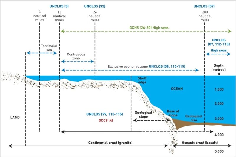
Figure above shows Legal boundaries of the ocean from territorial sea to exclusive economic zone and onto the high seas (figures in parenthesis refer to treaty articles).
_
In archipelagic waters and in the territorial sea, coastal states exercise sovereignty and may establish conditions for cables or pipelines entering these zones (UNCLOS, Article 79(4)). At the same time, the laying and maintenance of submarine cables are considered reasonable uses of the sea and coastal states benefit from them. Outside of the territorial sea, the core legal principles applying to international cables can be summarized as follows (UNCLOS, Articles 21, 58, 71, 79, 87, 112-115 and 297(1)(a)):
- the freedoms to lay, maintain and repair cables outside of territorial seas, including cable route surveys incident to cable laying (the term laying refers to new cables while the term maintaining relates to both new and existing cables and includes repair)
- the requirement that parties apply domestic laws to prosecute persons who endanger or damage cables wilfully or through culpable negligence
- the requirement that vessels, unless saving lives or ships, avoid actions likely to injure cables
- the requirement that vessels must sacrifice their anchors or fishing gear to avoid injury to cables
- the requirement that cable owners must indemnify vessel owners for lawful sacrifices of their anchors or fishing gear
- the requirement that the owner of a cable or pipeline, who in laying or repairing that cable or pipeline causes injury to a prior laid cable or pipeline, indemnify the owner of the first laid cable or pipeline for the repair costs;
- the requirement that coastal states along with pipeline and cable owners shall not take actions which prejudice the repair and maintenance of existing cables.
These traditional rights and obligations were carefully codified by the UNCLOS drafters who were familiar with the historical state practice of cables. Parts IV to VII of UNCLOS set out the rights and obligations in the following UNCLOS designated zones: archipelagic waters, the EEZ, the continental shelf and the high seas (Figure above). UNCLOS treats all cables the same, whether they are used for tele- communications or power transmission or for commercial, military or scientific purposes.
_
Cross-Jurisdictional Nature of Cables:
International commercial undersea cables cross international boundaries and land in two or more sovereign states. Domestic cables connect to jurisdictions within the same country, sometimes crossing international waters to connect domestic landing sites. Most cables cross multiple jurisdictions (e.g., international, national, state, local).
The geographic extent of U.S. jurisdiction over international undersea telecommunications cables is generally based on international agreements. These include, but are not limited to, the 1884 International Convention for the Protection of Submarine Telegraph Cables and the United Nations Convention on the Law of the Sea (UNCLOS). UNCLOS establishes national boundaries for party nations that extend up to 12 nautical miles from the baseline of the coast of the nation, and include the “exclusive economic zone” or EEZ, which extends up to 200 nautical miles from the baseline. While the United States has not ratified UNCLOS, it has generally abided by its terms, as dictated by Presidential Proclamation 5030.
_
Figure below depicts UNCLOS maritime zones and coastal nation rights. UNCLOS grants all nations the freedom to lay and operate undersea cables beneath the “high seas” and on the continental shelf, within a coastal nation’s EEZ, subject to a coastal nation’s rights “to take reasonable measures for the exploration of the continental shelf, the exploitation of its natural resources and the prevention, reduction and control of pollution from pipelines.” Thus, commercial undersea telecommunications cable segments crossing into U.S. territorial waters and landing in the United States, its territories and possessions are subject to oversight and regulation by the U.S. government.
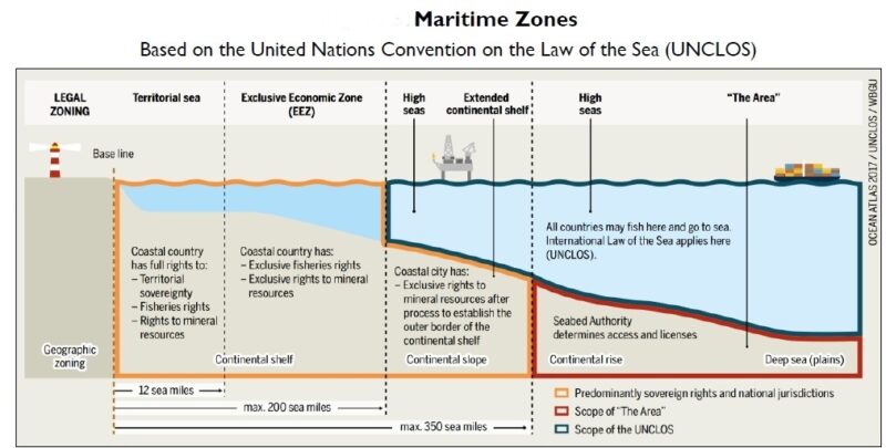
Figure above shows Maritime Zones Based on the United Nations Convention on the Law of the Sea (UNCLOS).
Notes: UNCLOS Part VII, Article 86, related to the “high seas,” applies to “all parts of the sea that are not included in the exclusive economic zone, in the territorial sea or in the internal waters of a [nation], or in the archipelagic waters of an archipelagic [nation].” In UNCLOS Part XI, Article 133, “the Area” is at or beneath the seabed extending beyond the continental slope.
Within their offshore boundaries, coastal states have “(1) title to and ownership of the lands beneath navigable waters within the boundaries of the respective states, and (2) the right and power to manage, administer, lease, develop and use the said lands and natural resources.” Thus, with cables, there are often multiple and overlapping jurisdictions.
_
The laying and maintenance of telecommunications cables is a reasonable use of the sea, and in 159 years of use, there has been no irreversible environmental impact. UNCLOS and state practice have provided adequate governance for international cables outside of national waters, and state practice increasingly recognizes the importance of protecting cables from activities that could damage them. The corresponding benefits of cable protection zones for biodiversity conservation have also been recognized. Yet increasing use of the oceans and seabed is likely to result in more conflicts between users. This may require future changes in the existing international legal regime. Careful planning may also be necessary to avoid adverse impacts on vulnerable seafloor ecosystems and biodiversity. Consistent with past practice and recognizing the importance of cables to the world’s infrastructure, any change to the existing international law requires express provisions in an international treaty.
______
Local Jurisdictions:
National regulations may apply to cable landings and maintenance in territorial waters, ensuring adherence to local safety protocols and environmental standards. These organizations collaborate to set best practices for cable laying, maintenance, and protection and aim to reduce risks to marine life and underwater ecosystems. Coordinated regulation across jurisdictions helps prevent disruptions from human activities, natural events, and cable damage and preserves the global cable network’s integrity.
In the United States, submarine cable regulation falls under the jurisdiction of the Federal Communications Commission (FCC), a federal energy regulatory commission dedicated to managing telecommunications infrastructure. The FCC oversees the licensing of undersea fiber optic cables that land on U.S. shores, ensuring they comply with national security, environmental, and operational standards.
______
Cables as critical infrastructure:
An emerging trend is for states to treat international cables in national maritime zones as critical infrastructure that deserves strong protection to complement traditional international cable law. In that vein, Australia, consistent with international law, has legislated to protect its vital cable links by creating seabed protection zones that extend out to 2,000 m water depth. Bottom trawling and other potentially destructive fishing practices, as well as anchoring, are prohibited inside these zones. New Zealand has also enacted legislation that established no-fishing and no-anchoring zones around cables (Submarine Cable and Pipeline Protection Act (1966)). The trend is expected to continue because most nations depend on cables for participating in the global economy and for national security, e.g. the United States relies on cables for over 95 per cent of its international voice and data traffic, only 7 per cent of which could be carried by satellites if the cables were disrupted (Burnett, 2006). These developments sometimes go hand in hand with conservation, as restrictions on trawling to prevent cable damage can also provide direct benefits for bio diversity by protecting vulnerable seabed ecosystems and species such as corals and sponges (CBD, 2003).
______
______
Legal vulnerabilities:
Submarine cables are internationally regulated within the framework of the United Nations Convention on the Law of the Sea (UNCLOS), in particular through the provisions of Articles 112 and 97, 112 and 115, which mandate operational freedom to lay cables in international waters and beyond the continental shelf and reward measures to protect against shipping accidents.
However, submarine cables face significant legal challenges and lack specific legal protection in UNCLOS and enforcement mechanisms against emerging threats, particular in international waters. This is further complicated by the non-ratification of the treaty by key states such as the U.S. and Turkey. Many countries lack explicit legal provisions to criminalize the destruction or theft of undersea cables, creating jurisdictional ambiguities that organized crime can exploit. Other legal frameworks, such as the 1884 Convention for the Protection of Submarine Telegraph Cables are outdated and fail to address modern threats like cyberattacks and hybrid warfare tactics. The unclear jurisdiction and weak enforcement mechanisms, demonstrate the difficulty to protect submarine cables from organized crime.
The Arctic Ocean in particular exemplifies the challenges associated with surveillance and enforcement in vast and remote areas, leaving a legal vacuum that criminals may exploit. In the Arctic, the absence of a central international authority to oversee submarine cable protection and the reliance on military organizations like NATO hinders general coordinated global responses.
Organizations such as the ICPC thus highlight the need for updated and more comprehensive legal frameworks to ensure the security of submarine cables.
_
Deterrence by punishment:
Better detection of subsea cable attacks is necessary—but not sufficient—for comprehensive cable protection. As stated in previous CSIS research, deterrence by punishment has its own role to play. At first glance, U.S. law provides sparse punishment options for wilfully damaging a submarine cable: a misdemeanour offense, up to two years in jail, and a fine up to $5,000. But it also provides for private remedies and explicitly notes that criminal punishments are not a bar to a suit for damages. Much ink has been spilled documenting the various challenges of punishing subsea cable attacks, including dated international instruments, consortium cable ownership, and cables that cross multiple jurisdictions. But private remedies are an underutilized tool to deter bad actors, and it is time for cable owners to adopt a bias for action in the courtroom.
There are also promising legislative and regulatory developments to better protect subsea cables and bolster legal accountability for intentional damage. In September 2025, the U.S. House of Representatives passed the Undersea Cable Control Act, which seeks to prevent foreign adversaries from acquiring items needed to support the construction, maintenance, or operation of undersea cable projects. Two months later, the Strategic Subsea Cables Act of 2025 was introduced in the Senate, which would bolster punishments for subsea cable damage and require the president to impose sanctions against foreign individuals who have intentionally damaged subsea fiber-optic cables. These legislative developments, coupled with the Federal Communication Commission’s national security–focused rulemaking on submarine cable landing licensing, highlight growing political will to better prevent and punish intentional cable damage; laudable and timely efforts. Further protecting subsea infrastructure should be a bipartisan priority.
______
______
Section-19
Earthquakes, tsunamis and climate change detection by subsea communication cables:
Earthquakes do something that humans and their instruments cannot: they pass through the crust into the molten center of the planet. As seismic waves move through the crust, mantle, and core, they illuminate the Earth’s structure in roughly the same way that an X-ray illuminates muscle, bone, and cartilage. The areas where oceanic plates dive beneath continents, known as underwater subduction zones, are particularly mysterious. Many of the worst earthquakes happen there, and the zones often run parallel to densely inhabited coastlines, for hundreds of miles. The earthquakes in the ocean are fundamentally different from the ones we have on land. Some recent studies suggest that plates in subduction zones not only rupture suddenly but can also creep slowly, perhaps over the course of a month, in a way that plates in other zones do not. Seafloor seismometers could measure the creep and map the pressure on different parts of the seafloor, pinpointing the fault zones that are most vulnerable to larger tremors. The problem is that there are so few seafloor seismometers to collect data in subduction zones.
_
Scientists have deployed many seismometers on land but relatively few on the seafloor, where the cost of installation is often prohibitive. Yet earthquakes beneath the ocean, and the tsunamis they cause, are some of the most destructive and deadly natural disasters. In 2004, a 9.1-magnitude tremor near Sumatra created a tsunami that killed an estimated two hundred and thirty thousand people. In 2011, a 9.1-magnitude quake near Japan caused a tsunami that killed nearly twenty thousand people and led to the Fukushima nuclear disaster. If scientists could anticipate the movements of tectonic plates, or provide early warning of tsunamis, it would be a major, life-saving advance.
_
Tsunamis are a series of massive waves triggered by sudden displacement of ocean water, most typically caused by the sudden ground motion of the sea floor. Tsunamis can be minor, or they can be devastating, such as 2004’s Indian Ocean tsunami, which killed nearly 230,000 people. Unlike earthquakes that happen suddenly and are hardly avoidable, even though some early warning systems exist, tsunamis generally take more time to build up and reach the coast. This means that early warning systems are more efficient for tsunamis. Yet, what is hard is to assess the magnitude of a tsunami before it reaches the coast. Therefore, offshore instrumentation is needed, which is costly and hard to maintain.
_
The world has a number of different earthquake detection systems deployed or in development today:
- Land-based detectors are the backbone of seismic detection, but as the name suggests they can’t always be located close to potential seismic subsea zones.
- Ocean-based Deep-ocean Assessment and Reporting of Tsunamis (DART) buoys are an excellent solution, but there are very few of them, and they are frequently out of action because of harsh conditions or even vandalism. A buoy float on the ocean surface and tethered to a tsunameter on the ocean floor. A tsunameter detects and measures tsunamis in the deep ocean using a sea-floor pressure sensor anchored at the bottom, which transmits data via acoustic signals to a surface buoy, which then relays it to satellites and warning centers. This real-time detection allows for monitoring waves as small as 1 millimeter in 6,000 meters of water.
- The SMART (Science Monitoring And Reliable Telecommunications) Cables initiative includes seismic, pressure, temperature, and acoustic sensors that can be installed in adapted subsea repeater modules, or even in separate dedicated modules along the cable.
One of the obvious factors in early warning is that the closer a detector is to the epicenter, the earlier the warning can be to those in danger. For every 200 km the detector is from the epicenter, there is an additional one minute of delay for a potential warning of an impending tsunami.
_______
_______
Using Existing Submarine fibreoptic cables as a Tsunami Warning Network:
Using the hundreds of existing submarine cables as seismic detectors is a tempting proposition and would buy time for a new generation of dedicated SMART Cables to come into service.
-1. Distributed Acoustic Sensing (DAS):
The DAS technique works by monitoring photons—particles of light—that travel through fiber optic cables. As light travels in a wave through the cables, some photons are refracted back to the beginning of the cable. These photons are refracted backward and at a given time, the amount of light that returns to the interrogator is proportional to the deformation along the cable.
Researchers initially used these cables to detect earthquakes. Earthquakes release a massive amount of energy in a very short amount of time. The big question was whether the cables could detect the much more subtle movement of tsunamis. The period between the crest of waves in a tsunami can be incredibly long—up to tens of minutes and several miles between the crest of waves. Earthquakes generally have much higher energy and shake very quickly, while tsunamis have very broad waves. So the question is, can we use these techniques to monitor very long period waves? The researchers are unsure what characteristic of the tsunami causes a change in the fiber optic cables. Pressure-induced deformation from extra water on top of the cables could cause fibers within them to stretch, changing how photons are refracted. Temperature could cause a similar change, but more research is needed to determine exactly how the fibers are impacted.
As light travels down glass fibers, it reflects off randomly oriented defects. When an acoustic or pressure wave—whether from a whale song or an earthquake—crosses the fiber, it stretches and squeezes the defects, causing a phase shift in the light they reflect back to the cable’s source. Measuring those shifts can turn the fibers into a dense array of strain meters. So far, so good—but seafloor cables are interrupted by repeaters, spaced every 75 kilometers or so. The repeaters amplify light for its long journey across the ocean, but dampen the faint back-reflections along that fiber. But these relays didn’t have to be showstoppers. The bundles of fibers in each cable resemble divided highways: Light travels out on some fibers and returns on others. But at each repeater there is a “loop-back,” designed to monitor fiber health, that allows light to jump the median, as it were, and travel back on one of the return fibers. These built-in bypasses enabled researchers to send defect reflections from each stretch back along return fibers, where they would be amplified by repeaters rather than blocked by outgoing ones. With some sophisticated computing, the researchers showed, they could recover reflections even from the farthest sections of the cable—creating, in effect, a dense 2D array of transoceanic seismometers. Scientists eager for the data wouldn’t need their own dedicated fiber—only a laser that piggybacks on the commercial cable, at higher frequencies than the internet traffic. The beauty of this tech is that it can run on legacy cables.
_
Earlier technologies with DAS had limitations: it can only provide data near the ends of each cable. It doesn’t work in the much longer stretches of cable that rely on repeaters that boost signals during their journey under the ocean. As the backbone of global internet connectivity, long-haul submarine cables usually have surprisingly few fiber strands (~2 to 6 pairs). Therefore, unused strands of fiber (called dark fibers), which are required for DAS, are rare. These limitations have been overcome as discussed in preceding paragraph.
_
-2. Brillouin Optical Time Domain Reflectometry:
BOTDR (Brillouin Optical Time Domain Reflectometry) is based on Brillouin scattering and measures mechanical strain and temperature changes. Here, too, a laser is sent through the fibre. The light hits the crystal lattice of the glass fibre. Changes in tension or temperature led to a change in Brillouin scattering, which is measured along the fibre. This allows temperature and tension curves to be recorded over distances of several kilometres. BOTDR is particularly suitable for the long-term monitoring of underwater deformations and contributes to the analysis and prediction of earthquake risks.
Both DAS and BOTDR technologies enable the detection of even the smallest deformations in the cable, effectively monitoring activity on the seabed.
_
-3. State of polarization (SOP):
Google shows how subsea cables can provide earthquake and tsunami warnings:
The pulsing light encounters distortions as it travels thousands of kilometres across the cable. At the receiving end, the light pulses are detected, and the distortions are corrected by digital signal processing. One of the properties of light that is tracked as part of the optical transmission is the state of polarization (SOP). The SOP changes in response to mechanical disturbances along the cable and tracking these disturbances enables to detect seismic activity.
Whereas the SOP of the transmit laser is stable over a long time scale (e.g., days), the output SOP at the receiver end is, in general, different from the input SOP and changes over time owing to various external perturbations to the fiber. For terrestrial fibers, the output SOP can be chaotic and hard to interpret owing to substantial temperature variations along cable and air flow or human-, animal-, and/or traffic-induced vibrations when integrated over the entire optical path. Extreme SOP transients with up to 5 Mrad/s anomalies were observed during lightning strikes. However, by making orders-of-magnitude more sensitive measurements, it was found that the output SOP of the Curie transcontinental submarine cables can be much more stable compared with that of terrestrial cables, because the absolute majority of the path is in the deep ocean with almost constant temperature and minimal mechanical or electromagnetic perturbations. Therefore, strong seismic waves or long-period water waves produced by earthquakes close to the Curie cable can cause distinct and observable SOP anomalies as seen in figure below.
Figure below shows Principles of polarization-based geophysical sensing:
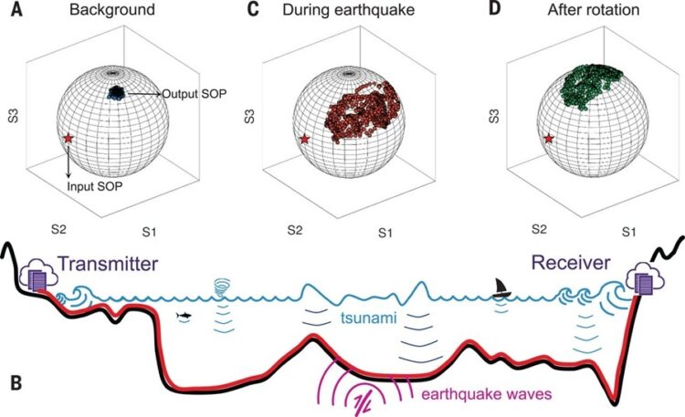
(A) The state of polarization (SOP) at the receiver is monitored routinely (blue dots on the Poincaré sphere) while the input SOP stays stable (red star). For the Curie cable, the output SOP is robust, owing to relatively minimal perturbations along most of its path in the deep ocean (B). The robustness allows us to detect earthquakes or ocean waves that produce SOP anomalies by shaking or pressuring the cable (C). Because the three Stokes parameters are normalized to 1.0, only two are independent. In this study, researchers rotate the Stokes parameters to the north pole of the Poincaré sphere and focus on analyzing the S1 and S2 parameters after rotation (D).
Note:
The Stokes parameters are a set of values that describe the polarization state of electromagnetic radiation.
The Poincaré sphere provides a visual method for representing polarization states and calculating the effects of polarizing components.
_
-4. Detection of Tsunami Signals by electric field:
Tsunamis may be detectable with underwater fiber-optic cables, according to a new detailed model of the electrical fields the moving water generates. The charged particles in the ocean water interact with Earth’s magnetic field to induce voltage of up to 500 millivolts in the cables that ferry internet traffic around. With relatively simple technology, those voltage spikes could serve as a tsunami-warning system for nations that can’t afford large arrays of other types of sensors. Rich countries like the United States can install sea bottom pressure arrays like those used by the Pacific Tsunami Warning Center. These directly detect the motion of large amounts of water. But some countries can’t afford to install and maintain those arrays, so it could be critical to have a lower-cost alternative.
The salt in ocean water makes it a good electrical conductor. Positively charged sodium and negatively charged chlorine ions in the solution are free to move. In a large movement of ocean water, these ions are carried across the Earth’s magnetic field creating an electrical field.
Decades ago, Bell Labs researchers revealed that the movement of ocean water after the 1992 Cape Mendocino earthquake created “a large-scale motional electric field” that was detectable by an underwater cable. But the work wasn’t followed up because alternative technologies were available that could take better measurements.
______
______
Smart cables:
SMART – short for Scientific Monitoring and Reliable Telecommunications – cables are designed for environmental monitoring. They are a joint initiative by the International Telecommunications Union, the World Meteorological Organization and UNESCO’s Intergovernmental Oceanographic Commission. These cables are equipped with sensors that measure vital environmental data in the ocean. This data includes seismic activity (accelerometers), temperature fluctuations and pressure changes. It can be used to improve early-warning systems for tsunamis and earthquakes as well as tracking changes in the climate. Undersea internet cables are being transformed into a global, real-time early warning system for tsunamis and earthquakes by incorporating specialized sensors into repeaters, offering 5–30 minutes more detection time. SMART cables will resolve processes ranging in temporal scale from earthquake seismic signals and tsunamis to secular climate trends and will need to support both real-time and delayed-mode applications to facilitate hazard monitoring and research. Data generated by SMART cable sensors will be transmitted along the underlying cable to a shore station where it may be stored in raw form, processed, and transmitted onward to data repositories, national agencies, and academic institutions as seen in figure below.
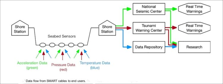
Seismic and pressure sensor data that will be used for early warning functions must be forwarded immediately, with minimal latency. Data will be processed and transmitted in recognized formats, such as SeedLink, to ensure compatibility with existing data processing and archival systems.
_
Multiple benefits:
Widespread deployment of SMART subsea cables could greatly boost scientific understanding of conditions related to climate change, ocean circulation, sea level monitoring, and the structure of the Earth itself. At the same time, significant use of the technology could vastly improve current knowledge regarding earthquakes occurring in the Earth beneath the oceans.
The inclusion of high-sensitivity accelerometers and pressure sensors on SMART cables holds great potential for significant advances for the field of seismology by improving our capacity to detect and locate small earthquakes below the ocean floor, improving our ability to determine the rupture type and dynamics for larger offshore earthquakes, and enhancing our ability to image the interior of the Earth, both locally and globally, from earthquakes occurring all around the globe.
With their potentially broad geographic reach, SMART cables have the potential to improve upon the capabilities of existing ocean-based tsunami detection systems. As a tsunami warning system, SMART cables can provide broader coverage and greater reliability than the existing network of moored/buoy-based detection systems. More accurate data regarding tsunami activity can save lives as well as minimize the likelihood of unnecessary warnings and evacuations.
_
Projects in development:
The cost to deploy the SMART subsea systems is expected to be 10% more than the expense associated with installing a telecommunications cable. Typical submarine cable system costs range between $20,000 and $40,000 per kilometer.
In November 2021, the nonprofit Gordon and Betty Moore Foundation awarded a $7.2 million grant to the University of Hawaii to support the development of the overall SMART initiative as well as the integration of SMART sensors into a subsea telecommunications cable in the Vanuatu-New Caledonia region of the South Pacific Ocean. This project is in the planning phase.
Other projects in various stages of development include a demonstration effort involving a 19 km long cable to be deployed in the western Ionian Sea by two Italian research institutes. In French Polynesia, the government is considering the inclusion of SMART subsea technology as part of a planned 820 km extension of an existing undersea cable system. Meanwhile, in Portugal, an existing 3,700 km undersea cable system linking the mainland with the Azores and Madeira archipelagoes is scheduled to be replaced in the next several years. The government is requiring that the replacement include environmental and seismic monitoring capabilities.
SMART systems are under consideration in other parts of the world, including the Mediterranean Sea; Indonesia; mainland New Zealand to the Chatham Islands; New Zealand to McMurdo Bay in Antarctica; Chile to King George Island, off the coast of Antarctica; Chile to Sydney, Australia; and Norway to Japan via the Northwest Passage along the northern coast of North America.
______
______
Using Submarine Communications Networks to Monitor the Climate:
Climate change is driving a rapid, record-breaking increase in ocean temperatures, with the ocean absorbing more than 90% of the excess heat trapped in the Earth’s system by greenhouse gas emissions over the past 50 years. This massive heat intake has profound consequences, leading to ocean expansion, sea-level rise, melting ice sheets, and severe disruptions to marine ecosystems.
_
Temperature and salinity are basic elements of the ocean. They govern the density of water and thus, along with wind and solar forces, the overall circulation of the world’s oceans. If the water temperature, salinity and pressure could be measured on the ocean floor at many locations, including “choke points”, changes in the planet’s climate could be monitored in this crucial part of the Earth’s climate system.
The polar ice sheet is shrinking and summer sea ice is likely to disappear in the foreseeable future, due to rises in temperature brought about by increases in greenhouse gases (GHG). Global warming causes the polar ice to melt, consequently reducing the ocean’s capacity to store GHG in deep waters, because there is less solubility at higher temperatures. This further reinforces atmospheric warming.
The deepest water mass covering the ocean floor is formed in the polar region as warm, salty water is cooled and sinks. This will likely be affected by climate change, affecting water temperature and salinity, and, in turn, the formation of the overall volume and circulation of deep oceanic waters. Since these deepest waters are formed at the surface of the polar seas through interaction with the air, changes in water temperature and salinity due to ice-melting and atmospheric GHG are transmitted from the ocean surface to the bottom, and eventually back to the surface as part of the “ocean conveyor belt”.
_
Oceanographers have a wide range of tools at their disposal to monitor the ocean, all with attendant advantages and disadvantages. Satellites can only monitor surface quantities, such as sea surface height, wind stress and temperature. Research vessels can obtain detailed measurements of water temperature and composition at depth, but only from a tiny portion of the sea and rarely on a regular schedule. The Argo program is a global array of nearly 4,000 autonomous, free-drifting profiling floats that constantly measure the temperature and salinity of the upper 2,000 meters of the world’s oceans but these buoys cannot go below 2,000 metres in deep seas. At present, oceanographers cannot measure waters at the ocean floor due to their vast extent and volume. Particularly, the high pressure at abyssal depths (~6,000 m) and complicated bottom topography cause finding appropriate instrumentation to be extremely difficult. In ocean ship cruise surveys and autonomous float measurements, the sea bottom is intentionally avoided, due to possible damage of the instruments. Therefore, measurement of polar-formed waters at the ocean floor is virtually non-existent. However, submarine telecommunication cables lie on the sea floor and could fill this gap. They can be used to measure on a continuous basis the bottom water they run through – something that cannot be done by other means. At the same time, electric signals from the cables can yield information about the ocean currents they run through, as electromagnetic signals and cable resistance vary when ocean currents and temperature change. Cables can also be used to provide power to, and transmit data from, observatories on the sea floor, as exemplified by the recently installed NEPTUNE Canada and Japanese DONET systems.
_
There is a significant opportunity for the telecommunications industry to redesign a new generation of cable repeaters to provide climate data to new stakeholders, in addition to providing their normal telecommunication services. The new repeaters could have built-in sensors to measure climate variables such as temperature, which would become a cost-effective long-term climate change monitoring network. The number of telecommunication cables deployed in the oceans will only increase, and the new generation of cable repeaters would be able to deliver vital climate change monitoring data. The repeaters used currently have space to integrate the temperature, salinity and pressure sensors inside the box or repeater housing, through holes for measuring environmental temperature (with thermistors), salinity (with sensors to measure sea water conductivity) and pressure (with pressure sensors). These sensors are currently being used in oceanographic instruments such as ConductivityTemperature-Depth (CTD) and mooring equipment near or at the ocean bottom. The measured signals can be converted and then transmitted to the shore stations by dedicated fibres and lines.
______
______
Section-20
Research and Innovation:
_
Emerging innovations in Submarine Optical Fiber Cable:
Emerging innovations are fundamentally reshaping the future of Submarine Optical Fiber Cable Market by pushing the boundaries of capacity, efficiency, and resilience. Advancements in fiber optic technology, such as spatial division multiplexing (SDM) and advanced modulation techniques, are enabling a significant increase in data carrying capacity, making existing and future cables capable of handling unprecedented traffic volumes. These innovations are crucial for meeting the exponential growth in global data consumption without continually laying entirely new cables, thus optimizing infrastructure investments and reducing environmental impact. Furthermore, innovations in undersea cable monitoring and repair technologies are enhancing network reliability and operational longevity. The development of advanced sensors, autonomous underwater vehicles (AUVs), and AI-powered predictive analytics allows for more precise fault detection and proactive maintenance. This minimizes downtime and reduces the costly, time-consuming process of manual repairs. These technological leaps are not only improving the performance of current networks but also facilitating the deployment of cables in more challenging and remote environments, thereby expanding the reach and robustness of global connectivity.
_
The demand for bandwidth continues to grow exponentially, driven by the increasing popularity of streaming video, cloud computing, and other data-intensive applications. This means that the submarine cable network must continue to expand and evolve.
Innovative trends include:
- Spatial Division Multiplexing (SDM): Massive increase in total system capacity (over 300 Tbps) by utilizing 12–24+ fiber pairs, while simultaneously reducing the cost-per-bit and power consumption per fiber pair.
- Advanced Modulation Techniques: Boosts data transmission efficiency over long distances.
- Enhanced Cable Materials: Development of stronger, more durable, and environmentally friendly cable coatings.
- Autonomous Underwater Vehicles (AUVs): Used for precise cable inspection, monitoring, and potentially localized repair assistance.
- AI-Powered Predictive Maintenance: Algorithms analyze data to anticipate and prevent cable faults, reducing downtime.
- Integrated Subsea Power Systems: Innovations enabling co-location of power and data transmission for remote applications.
- Enhanced Repeater Technology: Enables longer unrepeatered spans and improved signal quality.
- Real-time Cable Monitoring: Integration of sensors for continuous health checks and damage detection.
- Open Cable Systems: Trend towards interoperable systems allowing different vendors’ equipment.
- Optimized Routing: Strategic cable placement to minimize latency and maximize network efficiency.
- Quantum Communication Cables: Future cables could use quantum encryption for unbreakable cybersecurity.
These advancements will ensure that the submarine cable network remains a reliable and robust foundation for global communication for years to come.
______
Satellite and laser may make undersea internet cables obsolete:
Optical data communication lasers can transmit several dozen terabits per second despite numerous disruptive air turbulences. Researchers at ETH Zurich, together with European partners, demonstrated this between Jungfraujoch and Bern. This could soon eliminate the need for the costly construction of undersea cables.
Satellites could soon replace the expensive undersea cables as the internet backbone.
The backbone of the Internet consists of a dense network of fiber-optic cables, each capable of transporting up to more than a hundred terabits of data per second (1 terabit = 10¹² digital 1/0 signals) between network nodes. The continents are connected via the deep sea – and this is enormously expensive: a single cable across the Atlantic requires investments of several hundred million dollars. The specialized consulting firm TeleGeography currently counts > 600 active undersea cables, with the number steadily increasing.
Soon, however, this effort may no longer be necessary. Scientists at ETH Zurich, together with partners from the aerospace industry, have demonstrated optical terabit data transmission through the air as part of a European Horizon 2020 project. In the future, this will enable backbone connections via low-Earth-orbit satellite constellations that are significantly cheaper and much faster to deploy.
The project partners did not test their laser system with a satellite in orbit, but rather through a 53-kilometer transmission from the mountain ‘Jungfraujoch’ to Bern (Capital of Switzerland). “Our test route between the High Alpine Research Station at ‘Jungfraujoch’ and the Zimmerwald Observatory of the University of Bern is, from the perspective of optical data transmission, significantly more challenging than between a satellite and a ground station,” explains Yannik Horst, the lead author of the study and a researcher at ETH Zurich in the Institute for Electromagnetic Fields, led by Professor Jürg Leuthold. The laser beam had to travel through the dense, near-ground atmosphere along the entire route. The movement of the light waves – and thus the data transmission – was influenced by the diverse turbulence of air currents above the snow-covered high mountains, the water surface of Lake Thun, the densely built-up Thun agglomeration, and the Aare plain. The extent to which this shimmering of the air, caused by thermal phenomena, disturbs the smooth propagation of light can be seen with the naked eye on hot summer days.
Internet connections via satellites are not new. The most well-known example today is Elon Musk’s Starlink constellation, which, with over 2,000 low-Earth-orbit satellites, brings internet access to nearly every corner of the world. However, the technologies used to transmit data between satellites and ground stations are significantly less powerful. They operate like Wi-Fi (Wireless Local Area Network) or mobile networks in the microwave portion of the frequency spectrum, with wavelengths of several centimeters.
In contrast, optical laser systems work in the near-infrared light range, with wavelengths around 10,000 times shorter, on the order of a few micrometers. This allows them to carry correspondingly more information per unit of time. To receive a sufficiently strong signal over long distances, the laser’s parallelized light waves are sent through a telescope, which can have a diameter of several dozen centimeters. This broad light beam must then be aimed as precisely as possible at a telescope at the receiver, whose diameter is roughly the same size as the incoming light beam.
To achieve the highest possible data rates, the laser light wave is additionally modulated so that a receiver can detect several distinguishable states per oscillation. This allows more than one information bit to be transmitted per oscillation. In practice, different amplitudes (heights) and phase shifts of the light wave are used. Each combination of phase angle and amplitude defines a distinct information symbol. Using a 4×4 scheme, 4 bits can be transmitted per oscillation, and with an 8×8 scheme, 6 bits. The constantly changing turbulence of air particles causes the light waves in the center and at the edges of the light cone to travel at different speeds. At the receiver’s detector, the amplitudes and phase angles then add or subtract from each other, resulting in incorrect values.
To prevent these errors, the French project partner provided a so-called MEMS chip (Micro-Electro-Mechanical System) with a matrix of 97 movable mirrors. By moving the mirrors, the phase shift of the beam across its cross-section can be corrected along the currently measured gradient 1,500 times per second. Overall, this results in an improvement of the signals by roughly a factor of 500. This enhancement was essential to achieve a bandwidth of 1 terabit per second over a distance of 53 kilometers, as Horst emphasizes.
For the first time in the project, new, robust light modulation formats were also used. They massively increase detection sensitivity, enabling high data rates even under poor weather conditions or with low laser power. This is achieved through clever encoding of information bits onto properties of the light wave such as amplitude, phase, and polarization. “With our new 4D-BPSK modulation format (Binary Phase-Shift Keying), an information bit can still be correctly detected at the receiver with a very small number of only about four photons,” explains Horst.
The results of the experiment, presented for the first time at the European Conference on Optical Communication (ECOC) in Basel, are causing a worldwide stir, according to Leuthold: “Our system represents a breakthrough. Until now, it was only possible to either cover long distances with small bandwidths of a few gigabits or short distances of a few meters with high bandwidths using free-space lasers.” Additionally, the 1-terabit-per-second performance was achieved using a single wavelength. In a future practical application, the system can easily be scaled with standard technologies to 40 channels, reaching 40 terabits per second.
______
Researchers unlock fiber optic connection with E and S band:
Using an optical processor to operate in the E- and S-band ranges, UK researchers hit a transfer rate of 301 terabits per second. As spotted by Gizmodo, the international team achieved a data transfer rate of 301 terabits, or 301,000,000 megabits per second by accessing new wavelength bands normally unreachable in existing optical fibers—the tiny, hollow glass strands that carry data through beams of light. You can think of these different wavelength bands as different colors of light shooting through a (largely) standard cable. Commercially available fiber cabling utilizes what are known as C- and L-bands to transmit data. By constructing a device called an optical processor, however, researchers could access the never-before-used E- and S-bands. What’s particularly impressive and promising about the team’s achievement is that they didn’t need new, high-tech fiber optic lines to reach such blindingly fast speeds. Most existing optical cables have always technically been capable of reaching E- and S-bands, but lacked the equipment infrastructure to do so. With further refinement and scaling, internet providers could ramp up standard speeds without overhauling current fiber optic infrastructures.
______
72% of subsea cables would need to fail to impact Bitcoin:
Nearly three-quarters of all undersea fiber-optic internet cables (which carry about 95% of international internet traffic) would need to fail for there to be a significant impact on Bitcoin, according to a study released earlier this year. In research first published in February and last revised on March 12, researchers Wenbin Wu and Alexander Neumueller from the Cambridge Centre for Alternative Finance said they used P2P network data from 2014 to 2025 and 68 verified cable fault events to apply a country-level cascade model to determine Bitcoin’s physical infrastructure resilience. They claim it is the first longitudinal study of Bitcoin’s resilience to submarine cable failures, and it helps to answer a long-standing question about what would happen to Bitcoin if the internet were to be disrupted. The researchers found that the critical failure threshold for random cable removal sits at 0.72 to 0.92, meaning 72% to 92% of all “inter-country” submarine cables would need to fail before more than 10% of network nodes disconnect. However, the Bitcoin network was more vulnerable to targeted attacks on certain subsea cable chokepoints, with researchers calling it an “order of magnitude more effective,” with a critical failure threshold of 0.05 to 0.20. The study also found that Tor (The Onion Router) “creates a compound barrier to disruption,” given the current concentration of relay infrastructure in well-connected European countries. Tor is similar to VPNs (virtual private networks), bouncing web traffic through a chain of volunteer-run servers around the world, wrapping each hop in a layer of encryption for privacy, like the layers of an onion. The Bitcoin network uses Tor to obfuscate nodes, meaning their physical locations are hidden. The paper revealed that 64% of Bitcoin nodes are essentially “invisible” to researchers. The researchers concluded that 87% of the 68 verified historical cable fault events caused less than a 5% node impact, and cable events showed essentially zero correlation with Bitcoin (BTC) prices, or a statistically insignificant correlation coefficient of −0.02. They also note that the geographic diversification of BTC mining “has not materially altered infrastructure resilience,” which is consistent with physical cable topology rather than with hash rate distribution.
______
Subsea Power-over-Fiber Technology:
Power-over-Fiber (PoF) technology represents a revolutionary approach to addressing the dual challenges of data transmission and power delivery in subsea communication systems. This innovative solution combines optical fiber communication with remote power transmission, eliminating the need for separate electrical power cables in underwater installations. The technology leverages high-power laser diodes to transmit electrical energy through optical fibers, which is then converted back to electrical power at remote locations using photovoltaic cells or specialized photodiodes.
Power-over-fiber systems require proper impedance matching between optical components and electrical circuits to maximize power transfer efficiency. Impedance matching techniques involve designing circuits and interfaces that minimize reflection and optimize the coupling between fiber optic transmission lines and power conversion components. This ensures efficient power delivery from optical sources to electrical loads while maintaining signal integrity.
______
______
Section-21
My view:
One submarine optical cable carries more data than 100 satellites. This is because light carries far more information than radio waves, in addition to DWDM technology allowing 96 channels (wavelengths) in one fiber pair and several fiber pairs in one cable. Higher carrier wave frequency (light) carries more modulation than lower carrier wave frequency (radio wave) because higher frequency means there are more cycles per second available to fit information signal. So higher frequency carrier wave carries more information than lower frequency carrier wave. Fiber-optic cables transmit light with wavelengths range from 1300 nm to 1600 nm – the corresponding frequencies are above 100 THz, that is why they can support very high data rates. For comparison, 5G networks utilize a wide range of carrier frequencies, categorized into low-band (<1 GHz), mid-band (1-6 GHz), and high-band or millimetre wave (>24 GHz) while the standard for long distance light communication (The C-band) is around 1550nm, which is approximately 193,000GHz (193 THz). Future of internet lies in transmitting data using light in air rather than light in fibreoptics or radio waves in air; as radio spectrum, spanning from roughly 3kHz to 300GHz, is considered almost fully utilized due to intense demand from cellular, Wi-Fi, broadcasting, and satellite services; and submarine cables are difficult to install and repair facing constant threats from fishing, anchoring and sabotage. Recent developments show that escalating tensions in the Strait of Hormuz and the Red Sea have prompted major telecom projects to be delayed or rerouted. The Iran’s Revolutionary Guard issued a warning, suggesting that the undersea data cables running through the Strait of Hormuz are highly vulnerable to accidental or deliberate action. Multiple undersea cables in the Baltic Sea have been severed or damaged since Russia’s invasion of Ukraine. In September 2025, multiple major undersea fiber-optic cables in the Red Sea were severed, causing significant internet slowdowns and disruptions across Asia, the Middle East, and India.
_
Future of communication lies in light. Light is used for communication through fibreoptic cables on the land and under the sea but more research should be done to use light in the air. Low-frequency signals often achieve longer ranges and better non-line-of-sight coverage; high-frequency signals suit short-range, high-capacity links or require relay/dense infrastructure for coverage. Low frequencies penetrate walls/structures and water better; high frequencies are attenuated more by obstacles, rain, foliage, and atmospheric absorption. Radio waves are used for wireless communication because they can travel long distances, pass through obstacles like buildings, and are easy to generate and modulate for carrying information. They are low-energy, non-ionizing electromagnetic waves that can bend around obstacles and operate effectively through the atmosphere. Light is not widely used for wireless communication—compared to radio waves—primarily because it requires a strict line-of-sight, cannot penetrate obstacles like walls, and suffers from interference from ambient light sources like the Sun. While light (e.g., Li-Fi) offers massive, secure, and fast bandwidth, it is impractical for broad, through-wall connectivity.
_
Visible light is strongly emitted/absorbed by individual atoms, and therefore strongly interacts with it, whereas radio waves do not strongly interact with individual atoms and tend to pass through most matter with ease. This latter property is what makes radio waves so useful: you can listen to the radio or talk on your cellphone or use your Wi-Fi anywhere in your house, (mostly) regardless of any walls between your receiver and the source. Visible light has a much higher frequency, but doesn’t pass through barriers at all, which means at the very least it could not replace free-space radio communications. You could imagine going to even higher ultraviolet or X-ray frequencies, but at that point the electromagnetic waves become harmful to humans, so they are only used in limited applications and not for communications.
_
The rate at which data can be transmitted via electromagnetic waves is strongly dependent on the carrier frequency being used and the available bandwidth. Light may become a solution for transmitting more data in an electromagnetic spectrum that is already crowded with applications, and it seems worth exploring! Suppose we use near infrared light to transmit wireless data. Near infrared light encompasses a 300 THz range of frequencies, a roughly 1000 times larger than the entire radio frequency spectrum combined, at 300 GHz!
Li-Fi (Light Fidelity) is a wireless communication technology that uses light (LEDs) instead of radio waves (Wi-Fi) to transmit data at extremely high speeds. It offers faster, more secure, and interference-free connectivity, making it ideal for environments needing high performance, such as offices, hospitals, and secured areas, by modulating light intensity. Li-Fi utilizes visible light, infrared, or ultraviolet spectrums. Data is transmitted by modulating the intensity of LED bulbs at speeds imperceptible to the human eye, which is then detected by a photodetector (receiver) and converted back into data. Speed is potentially over 1 Gbps, exceeding traditional Wi-Fi. Range is limited compared to radio waves; light cannot pass through solid obstacles.
_
Shannon’s Theorem states that the maximum information rate we can pass through a system is related to the bandwidth occupied, and the signal to noise ratio of the signal. We have an issue with that big ball of nuclear fusion 93,000,000 miles away (The Sun) – it is the noise source. Have you ever tried to make a light source brighter than the sun? With lasers, this is possible. Laser light is used for air transmission because its coherent, highly focused beam allows for high-speed, secure, and long-distance data transfer without the need for physical cables. It provides higher bandwidth, minimal interference, and superior portability compared to radio waves, acting as a “wireless fiber”. The laser is very focused, and the receiver is highly filtered to look only for the bandwidth the laser is transmitting. Today’s fiber optic technology keeps the laser in the core, and is designed to keep everything else out of the core – so SNR is high. We have light that we need to see with, then if we modulated some of that visual bandwidth, or even went outside of the visual band, we have a problem with SNR – we can’t make the data light bright enough to overcome the ambient light to have a sufficiently high SNR to pass a reasonable volume of data. We could overcome some of this SNR problem with laser light and high quality optical or laser filters.
_
Free Space Optics (FSO) is a wireless communication technology that transmits data, voice, and video over the air using lasers or LEDs, providing high-speed, secure connectivity without physical fiber cables. Operating in the infrared spectrum, it offers bandwidths 10–100 times wider than radio frequencies (RF) over distances up to several kilometers, though it requires a clear line of sight. The reliability of FSO units has always been a problem for commercial telecommunications. Consistently, studies find too many dropped packets and signal errors over small ranges (400 to 500 meters). Military based studies consistently produce longer estimates for reliability, projecting the maximum range for terrestrial links is of the order of 2 to 3 km (1.2 to 1.9 mi). All studies agree the stability and quality of the link is highly dependent on atmospheric factors such as rain, fog, dust and heat. Relays may be employed to extend the range for FSO communications. Various satellite constellations that are intended to provide global broadband coverage, such as SpaceX Starlink, employ laser communication for inter-satellite links. This effectively creates a space-based optical mesh network between the satellites.
_
Recent research found that optical data communication lasers can transmit several dozen terabits per second despite numerous disruptive air turbulences. Researchers at ETH Zurich, together with European partners, demonstrated this between Jungfraujoch and Bern. The project partners did not test their laser system with a satellite in orbit, but rather through a 53-kilometer transmission from the mountain ‘Jungfraujoch’ to Bern (Capital of Switzerland), that is from the perspective of optical data transmission, significantly more challenging than between a satellite and a ground station. The laser beam had to travel through the dense, near-ground atmosphere along the entire route. To receive a sufficiently strong signal over long distances, the laser’s parallelized light waves are sent through a telescope, which can have a diameter of several dozen centimeters. This broad light beam must then be aimed as precisely as possible at a telescope at the receiver, whose diameter is roughly the same size as the incoming light beam. To achieve the highest possible data rates, the laser light wave is additionally modulated so that a receiver can detect several distinguishable states per oscillation. This allows more than one information bit to be transmitted per oscillation. The constantly changing turbulence of air particles causes the light waves in the center and at the edges of the light cone to travel at different speeds. At the receiver’s detector, the amplitudes and phase angles then add or subtract from each other, resulting in incorrect values. To prevent these errors, MEMS chip (Micro-Electro-Mechanical System) with a matrix of 97 movable mirrors was used. By moving the mirrors, the phase shift of the beam across its cross-section can be corrected along the currently measured gradient 1,500 times per second. Overall, this results in an improvement of the signals by roughly a factor of 500. This enhancement was essential to achieve a bandwidth of 1 terabit per second over a distance of 53 kilometers. Until now, it was only possible to either cover long distances with small bandwidths of a few gigabits or short distances of a few meters with high bandwidths using free-space lasers. Additionally, the 1-terabit-per-second performance was achieved using a single wavelength. In a future practical application, the system can easily be scaled with standard technologies to 40 channels, reaching 40 terabits per second.
_
The Earth curves at a rate of approximately 8 inches per mile, but this is not a linear measurement. The drop is cumulative based on the square of the distance. Because the Earth is spherical, your line of sight (a straight line) eventually becomes tangent to the surface, and anything beyond that point begins to disappear “bottom-first” over the horizon. For an average person standing at sea level, you can see about 3 miles (roughly 5 kilometers) before the curvature of the Earth causes the surface to disappear from your line of sight. The distance to the horizon depends entirely on how high your eyes are above the ground (or water).
_
Line of Sight or LoS is a type of electromagnetic radiation where the electromagnetic waves will travel only along a direct path from the transmitter to the receiver. This means that there are no obstacles in between them. Typical electromagnetic signals used for transmission include radio frequency (RF) and optical or light waves. Since the ability to visually see the transmitting antenna roughly (due to the inherently present path loss) corresponds to the ability to receive the signal at the receiving antenna, this propagation characteristic is referred to as the line-of-sight. The distance over which the signal travels is called the line-of-sight distance. The signals may also get refracted, diffracted, and/or reflected from the Earth’s atmosphere, which causes them to bend and propagate along a slightly curved path over long distances. These distances are much greater than the line-of-sight distance. This farthest possible distance of propagation is called the radio horizon.
_
The geometric LOS distance (d in km) can be approximated by formula:
d = 3.57 [√h1 + √h2]
Where:
h1 is the height of the transmitter (meters)
h2 is the height of the receiver (meters)
For a 100 km path, if both sides are at equal height, they would each need to be roughly:
100 = 3.57 [2√h]
√h = 100/ (3.57 X 2) ≈ 14
h ≈ 196 meters
Therefore, a minimum of ~200m towers on both sides is required for 100 km line of sight laser light propagation.
To have a direct line of sight over a distance of 100 km across the curved Earth, tower must be roughly 200m high. The Tokyo Skytree in Japan is the tallest self-supporting communication tower in the world, standing at 634 meters. We have construct 200 meter tall towers for 100 km laser light transmission.
_
I propose LG (light generation). We already have 2G, 3G, 4G, 5G and Wi-Fi using radio waves. LG is using light to transmit data similar to 4G/5G through air but 4G/5G uses radio waves while LG uses laser light. We already have laser light inter-satellite communications. We need more research and more innovation to use laser light to carry data between 200m tall towers spaced 100 km in line-of-sight laser light transmission on earth and between satellite and ground station. If laser light on earth can carry terabit data over 53 kilometers in air (already researched), we can make it 100 km between two 200m tall, line-of-sight towers. Future of communication lies in data transmission via laser light in air rather than glass fiber. It is difficult but not impossible.
______
______
Moral of the story:
_
-1. Submarine (subsea/undersea) communication cables refer to underwater fiber-optic cables that are laid on the seabed between land-based stations to carry telecommunication signals across stretches of ocean and sea, in which digitized voice, video & data signals are converted to coded light pulses and transmitted along optical glass fibres. Domestic undersea telecommunication cables lay point to point within a country to improve connectivity between regions within a country, and provide connectivity to the global internet. Some domestic cables cross into international waters when connecting two domestic points. International cables connect two or more countries; these enable connection between the countries and to the global internet. Submarine cables connect continents and their countries, mainland to islands, islands to each other, or several points along a coast. These cables connect every continent except Antarctica, and serve as the backbone for the global internet. The undersea telecommunication cable network carries about 95% of intercontinental global internet traffic, and 99% of transoceanic digital communications (e.g., voice, video and data) including trillions in international financial transactions daily. Undersea cables constitute a critical component of the internet delivery chain, serving as an integral part of the first mile infrastructure that facilitates internet access to a country.
_
-2. As of 2026, there are over 600 active and planned submarine fiber optic cables globally and 1700 cable landing stations. The largest concentration of submarine cables is found in the Atlantic Ocean (between Europe and the US), where there are over 400 cables. As of early 2026, the highest-capacity undersea cables in operation generally offer around 200–224 Tbps. The MAREA cable (spanning 6,605 km from the US to Spain) is widely cited as one of the highest-capacity, designed to carry 200–224 Tbps. Japanese IT multinational NEC plans to build a huge submarine cable for Facebook, with a capacity of up to 500Tbps across 24 fiber-pairs.
_
-3. Between 1850 and 2026, the submarine cable network has been able to provide a full range of services from telegraph messages, telephone, fax, data and now video and multimedia by Internet, as well as unlimited cloud and big data applications. In 1988, the first trans-oceanic fibre-optic cable was installed, which marked the transition when submarine cables started to outperform satellites in terms of the volume, speed and economics of data and voice communications.
_
-4. Optical fiber cables vs copper cables:
An optical fiber is a glass fiber that carries pulses of light that represent data via lasers and optical amplifiers.
- Main technical advantages of using fiber optical links are lower transmission losses and reduced sensitivity to noise and electromagnetic interference compared to all-electrical signal transmission. Metal wires are subject to higher signal loss, electromagnetic interference, and higher lifetime maintenance costs.
- Fiber optic cables offer substantially greater data transmission capacity and speed compared to traditional copper wiring, which is crucial for supporting modern applications like cloud services, IoT, and high-quality video streaming. Using dense wave division multiplexing, optical fibers can simultaneously carry multiple streams of data on different wavelengths of light, which greatly increases the rate that data can be sent to up to trillions of bits per second.
- Fiber systems are generally more durable and have a longer lifespan than copper cabling, reducing the frequency of replacements and maintenance. This also contributes to energy saving efficiencies.
- One disadvantage of fibre optics is that glass is more fragile than copper. Any sharp bend or crushing force may cause fibres to crack and signals to be lost. The minimum bend radius for fibre submarine cables is usually about 1 to 1.5 m (3 – 5 feet). A trawl door, beam trawl or dredge striking a fibre cable can easily render it useless without actually parting it.
- Optical cost 1.5 times more than copper cable.
- Compared with the submarine coaxial communication cable, the submarine optical cable needs to have a greater bending radius (less flexible), longer jointing time, a specialized optical repeater storage stack, and a “branching unit” (BU) installation.
_
-5. Higher carrier wave frequency carries more modulation than lower carrier wave frequency because higher frequency means there are more cycles per second available to fit information signal. So higher frequency carrier wave carries more information than lower frequency carrier wave. Fiber-optic cables transmit light with wavelengths range from 1300 nm to 1600 nm – the corresponding frequencies are above 100 THz, that is why they can support very high data rates. For comparison, 5G networks utilize a wide range of carrier frequencies, categorized into low-band (<1 GHz), mid-band (1-6 GHz), and high-band or millimetre wave (>24 GHz) while the standard for long distance light communication (The C-band) is around 1550nm, which is approximately 193,000GHz (193 THz).
_
-6. High-frequency electromagnetic waves travel shorter distances primarily due to higher attenuation (energy loss) over distance, smaller wavelengths that are more easily blocked by obstacles (diffraction), and faster energy absorption by the surrounding medium. These waves exhaust their energy faster than low-frequency waves, which pass through obstacles more easily. Wi-Fi uses radio waves rather than light because radio waves easily pass through walls, furniture, and bodies, allowing coverage throughout a home, whereas light (visible or infrared) is easily blocked. While light-based data transmission (Li-Fi) is faster, it requires direct line-of-sight and cannot penetrate opaque obstacles like radio waves do. Therefore, although light carries lot more information than radio waves, light transmission is not used in 4G, 5G and wi-fi.
Light is transmitted in optical fibers but not radio waves because fiber optic is a waveguide. Every waveguide has a critical “cutoff frequency”, below which conventional wave propagation ceases & a phaseless high attenuation mode occurs instead. The cutoff frequency is when the narrowest dimension of the waveguide is less than 1/4th wavelength of the electromagnetic energy. For fibers with core diameters on the orders of microns, “radio waves” even in multi GHz are still “too large” to fit into the waveguide structure. Unlike visible or infrared light, which travel via total internal reflection, low-frequency radio waves cannot propagate, and the dielectric glass material is ineffective for conducting radio frequencies, which would instead be absorbed or skip past the waveguide entirely.
_
-7. Optical fiber communication primarily uses infrared light (non-visible), typically generated by lasers or light-emitting diodes (LEDs). Laser light is used in submarine fiber optics because it is monochromatic (single wavelength), coherent, and highly directional, allowing for, much higher speed data transmission over longer distances. Lasers provide high-intensity light that experiences minimal signal attenuation (loss of power) and enables high-bandwidth, long-haul communication compared to other light sources like LEDs. These light signals operate at specific infrared wavelengths (such as 1550 nm) designed to minimize signal loss within the glass fiber core, and travel by total internal reflection.
Fiber-optic communication is mainly conducted in the wavelength region where optical fibers have small transmission loss. Today optical fibers show its lowest loss in the C-band (1530 to 1565 nm), and thus is commonly used in many metro, long-haul, ultra-long-haul, and submarine optical transmission systems combined with the WDM and EDFA technologies.
The L-band (1565 to 1625 nm) is the second lowest-loss wavelength band, and is a popular choice when the use of the C-band is not sufficient to meet the bandwidth demand. The same WDM and EDFA technologies can be applied to the L-band. Repeatered C+L-band WDM transmission is now commercially feasible, and is employed even for transoceanic submarine transmission systems.
_
-8. Optical modulation is when we change parts of light wave to send information for communication, primarily within fiber-optic systems. This lets devices send lots of data fast and without mistakes. This process dynamically alters properties of an optical carrier light wave—such as amplitude, phase, frequency, or polarization—to embed data. Its inverse, demodulation, extracts this information at the receiving end.
_
-9. There are two main types of fiber optic cable, the first is called single mode cable and the second is multimode cable. The core diameter of an optical fiber depends on whether it is single-mode or multi-mode. Single-mode fibers have a small core, typically 8 to 10 µ (most commonly 9 µ). Multi-mode fibers have larger cores, commonly 50 or 62.5 µ for telecommunications. Multimode fiber, as its name suggests, allows multiple light paths or modes to travel through the cable at once. In single mode fiber, all light from a pulse travel at about the same speed and arrives at roughly the same time, eliminating the effects of modal dispersion found in multimode fiber. This supports higher bandwidth levels with less signal loss over longer distances. It’s ideal for long-haul signal transmission applications like submarine cables.
_
-10. When the optical power travels from the transmitter to the receiver, light energy gets lost due to scattering and absorption. The fiber loss, fiber optic connector loss, and losses in splices can reduce the light levels below acceptable limits. That is why the optical power loss calculation is important when you are looking for reliable fiber-optic communication. It also determines how long the fiber optic cable can be extended without disturbing communications. Optical fiber losses, or attenuation, refer to the reduction in signal strength (power) as light travels through the cable, measured in decibels (dB). Major losses are caused by absorption (impurities), scattering (material imperfections), bending (structural, macro-bending / micro-bending), and connection losses (splices, connectors). OFC loss (attenuation) per km depends on fiber type and wavelength, typically ranging from 0.2 dB/km to 0.5 dB/km for single-mode (1550/1310nm) and 2.5 dB/km to 3.5 dB/km for multimode (850nm).
_
-11. Wavelength Division Multiplexing (WDM) is a fiber-optic technology that increases bandwidth by multiplexing multiple data signals, each using a unique wavelength (color) of laser light, onto a single fiber strand. This allows for multiple optical carrier channels to be transmitted through a single fiber, each carrying its own information. WDM is limited by the optical bandwidth of the amplifiers used to transmit data through the cable and by the spacing between the frequencies of the optical carriers with the minimum spacing often being 50 GHz (0.4 nm wide). CWDM (Coarse) uses wide 20nm spacing for short-range applications, while DWDM (Dense) uses narrow spacing (typically 0.8nm/100GHz or 0.4nm/50GHz) for long-haul transmission allowing 40, 80, or more channels within the C-band and L-band (1530–1625 nm). This dense spacing enables high-capacity, long-haul transmission, with 100 GHz (0.8nm) being standard for many networks and up to 96 channels can be potentially used in the C-Band with a channel spacing of 50 GHz (about 0.4 nm).
_
-12. DWDM benefits in submarine cables:
The major benefit of using DWDM technology is that it can transmit a large amount of data over a very long distance, which makes it very suitable for long-haul transmission. It can also be used with existing fiber optic cables with the means of increasing their data capacity as optical technology improves.
DWDM technology is useful when data needs to be sent across several states or even across oceans. Where it is much cheaper to install a DWDM system rather than laying down thousands of kilometers of new fiber.
Another benefit DWDM technology has for data transmission is that DWDM is protocol and bitrate independent, because as data flows through each wavelength, the channels do not interfere with one another. This means DWDM can carry different types of traffic such as voice, video, and text over a single fiber, which is very beneficial to service providers who offer multiple services to their customers. This non-interference also helps to maintain the integrity of data and enable the separation of users and other types of partitioning applications.
_
-13. A fiber pair is a common configuration in fiber-optic communications consisting of two distinct, individual optical strands used together to enable full-duplex (two-way) communication. One fiber is dedicated to transmitting data, while the second fiber receives data, allowing simultaneous, high-speed data flow in both directions. Typically, the higher the capacity per fiber pair of an undersea communication system the lower the cost per transported bit since the total system cost can be amortized over a larger capacity. This simple fact explains the drive towards higher and higher capacity in submarine systems.
_
-14. Since fiber pair capacity is simply the product of the repeater bandwidth (BW) and the spectral efficiency of the transmitted signals, fiber pair capacity can be increased in two ways. One, by increasing the repeater bandwidth and two, by increasing the spectral efficiency of the transmitted signals. Much effort has been devoted to maximizing both of these parameters. Repeater bandwidths up to 80 nm have been demonstrated as early as 2002 but so far commercial applications in the undersea space are limited to the full C-band of about 40 nm or 5 THz for various reasons.
Coherent techniques have enabled dramatic progress in spectral efficiency over the last few years. Coherent technology is the foundational enabler of modern submarine cable systems, utilizing advanced digital signal processing (DSP) and modulation (QPSK, 16-QAM) to significantly boost data rates, spectral efficiency, and capacity. It enables higher-order modulation formats, but these require stricter Optical Signal-to-Noise Ratio (OSNR) thresholds—typically 13-15 dB for 100G QPSK and 18-20 dB for 16-QAM—to ensure error-free transmission, making OSNR a critical performance metric for upgrading to higher data rate.
Modern submarine cables achieve spectral efficiencies (SE) exceeding 6–7 bits/s/Hz, with state-of-the-art trials reaching 7.52 bits/s/Hz on trans-Atlantic routes. These high rates are achieved using coherent transmission, high-order modulation (like 16QAM or 32QAM), and high-baud-rate transponders that maximize data throughput within a limited optical spectrum.
_
-15. Dense Wavelength Division Multiplexing (DWDM) and coherent technology form a formidable partnership in the domain of long-haul data transmission. The synergy between these two innovations boosts the capabilities of modern communication networks. DWDM and coherent technology enable signal transmission speeds of up to 800 Gb/s per wavelength, especially for ultra-long-haul and uncompensated submarine applications. Based on technology, DWDM / ROADM systems can typically support a range of 40 to 96 channels or wavelengths per fiber.
_
-16. The existing G.65x fibres have a limited maximum capacity because the maximum input power in an SMF is limited by an optical nonlinear effect, which results in limited improvement in the optical signal-to-noise ratio (OSNR). The total input power of all the DWDM channels is also restricted by a physical limitation, namely the fibre fuse. A fiber fuse is a catastrophic damage mechanism in optical fibers, where high-intensity laser light creates a plasma region that destroys the core, propagating toward the source. Thus, the maximum capacity in one SMF is limited to around 110 Tbit/s when an optically amplified transmission window and a spectral efficiency are assumed to be a C-L band and 10-b/s/Hz, respectively.
_
-17. SDM:
Spatial Division Multiplexing (SDM) is a new submarine cable paradigm that allows for higher total cable capacity by increasing the number of fiber pairs in a cable, even if capacity per pair is lower. SDM cables sacrifice spectral efficiency per pair in order to add more pairs and compensate with a higher cable capacity overall. SDM transmission technology utilizes the extra fiber pairs by performing the transmission across spatially diverse pathways (multiple fibers in this case). A key advantage of SDM is its ability to allow multiple fiber pairs to share pump lasers and other optical components. This contrasts with traditional subsea cables, where each fiber pair requires its own dedicated set of pump lasers. Implementing SDM is not only technologically advanced but also cost-effective. It enhances the cable’s capacity without significantly increasing costs. SDM entails massive increase in total system capacity (over 300 Tbps) by utilizing 12–24+ fiber pairs, while simultaneously reducing the cost-per-bit and power consumption per fiber pair.
One example is sufficient.
- Traditional Cable: 6 fibre pairs X 20Tbps each = 120 Tbps total capacity
- SDM Submarine Cable: 16 Fibre pairs X 16Tbps each = 256 Tbps total capacity
_
-18. How to increase capacity of submarine fibreoptic cables:
Global data traffic has been growing by 30 to 40% per year in line with the spread of 5G mobile communication, expansion of cloud services, increasing popularity of streaming video, AI and construction of data centers in respective countries. To meet this growing demand, there is a strong requirement to expand the transmission capacity through a submarine cable.
Before the 1990s, a single-wavelength transmission over standard single-mode fiber (SMF) was used. Then, wavelength division multiplexing technologies (WDM, DWDM) using optical fiber amplifier (EDFA) were introduced and chromatic dispersion became the main constraint for transmission capacity, and therefore, dispersion-shifted fiber (DSF), non-zero dispersion-shifted fiber (NZDSF) and dispersion- managed fiber (DMF) were adopted.
In the 2010s, the optical signal to-noise ratio (OSNR) emerged as the main constraint factor by the introduction of digital coherent technology. Higher OSNR enables higher spectral efficiency by allowing more complex, dense modulation schemes (like QAM), enabling faster, more reliable data rates within the same channel bandwidth. A higher OSNR indicates better signal quality, lower Bit Error Rate (BER), and longer signal reach. To improve OSNR, it is important to reduce fiber nonlinearity and transmission loss. Therefore, an optical fiber having low nonlinearity by enlarging effective area (Aeff) to 130 to 150 μm2, and ultra-low loss (0.15 dB/km) by applying pure silica core technology was optimal. This fiber represents very high performance compared with standard SMF (Aeff: 80 μm2, transmission loss: 0.18 to 0.20 dB/km).
In around 2020, transmission capacity per optical fiber almost reached the theoretical limit. Thus, space division multiplexing (SDM) technology was introduced to increase transmission capacity by increasing the number of fibers in a cable. Today, optical fibers with Aeff of 80 to 130 μm2 and ultra-low loss of 0.15 dB/km are utilized mainly.
To achieve more capacity, we need more submarine cables, more number of channels (C+L band system), more number of fiber pairs, increasing per fiber capacity, and increasing channel bandwidth i.e. transponder/modem capacity. By leveraging the latest SLTE modems alongside SDM, MCF, and C+L Band wet plants, we should be able to achieve submarine cables with total capacities in the multiple petabits per second (Pbit/s), where 1Pbit/s is 1,000,000,000,000,000 bits per second.
Over the last 40 years, the capacity of these optical cables has been increasing by 40 per cent yearly. It’s an exponential growth which in turn powers the exponential growth of the internet.
_
-19. New cable vs repurposed cable:
We first need to distinguish between a cable’s lit capacity vs potential capacity. Lit capacity is the amount of capacity a cable is currently equipped to handle. Potential capacity, on the other hand, is the theoretical maximum capacity that a cable can support if additional capital was invested to fully equip the cable system. In most major routes, the lit share of potential capacity is less than 30%. This would suggest that we can invest in existing cables and make use of the remaining unlit capacity, but this is generally not the case. It is normally possible to increase capacity during the cable’s lifetime by modifying the land-based parts of the system to provide significant increases in speed (in many cases to hundreds of times the original installed capacity). The entire wet segment, including the repeaters, are entirely agnostic with respect to the carrier signal. The number of lit wavelengths, the signal encoding and decoding, and the entire cable capacity is now dependent on the equipment at the cable stations at each end of the cable.
However, companies prefer laying out newer cables because they are far more technologically advanced. It is rare to upgrade an existing long-haul amplified undersea link, as the cost of laying a new link is not significantly higher than the cost of upgrading an existing link. The second reason is that old cables have few or no spare fibre pairs. While companies can make use of the unlit capacity by sharing existing fibre pairs, content providers like Facebook, Google, Microsoft and Amazon, given their large demand, prefer buying whole fibre pairs. There is a consensus that bandwidth demand is doubling every two years, and hence new cables are required to keep up. Other reasons for new cables include connecting some remote parts of the world that are still reliant on satellites and providing more options to economies that have only one or two cables, because any damage to these cables can cause massive disruptions.
_
-20. Satellite transmission vs subsea cable transmission:
Satellite internet is an ideal choice—and often the only choice—for people in rural areas that lack cable or fiber access. Satellites provide global broadcasts and communications for sparsely populated regions not served by cables. They also form a strategic back-up for disaster-prone regions. Satellites also have the advantage of distributing content from one source to multiple locations. Satellite internet provides broadband connectivity primarily to remote, rural, and underserved areas, bypassing the need for terrestrial cable infrastructure. It is used for residential high-speed internet, maritime/aviation connectivity, disaster response, IoT, and telemedicine, utilizing satellites to relay signals from user terminals to gateways. Satellites like those in the Starlink constellation do provide internet access but account for less than 1% of global data traffic.
Compared with satellite connections undersea cables have many advantages.
Undersea systems have fundamental advantage: massive capacity. A single fiber optic cable is able to transmit 250 terabits of data per second. When communications companies lay fiber optic cables, each cable contains dozens of individual fibers. A single satellite can transmit 260 gigabits of data per second and that bandwidth must be divided up among the thousands of customers using the internet simultaneously. One fiber pair can handle the entire daily traffic of countries like India or Japan. Cables can carry far more data at a fraction of the cost of satellites. LEO satellites, the preferred medium of satellite internet are costlier than undersea cables (USD 100-500 million). Satellite networks cost approximately USD 5-10 billion and have a shorter lifespan (5-10 years) than undersea cables (25 years).
Signal power loss (or attenuation) in satellite internet is a common phenomenon where the radio signal between the ground dish and the satellite weakens, resulting in lower speeds, high latency, or total service disruption. Satellite signals are impacted by weather and interference, while cables are largely protected beneath the sea.
Line-of-sight (LoS) is a fundamental requirement for most satellite communication systems, meaning the ground antenna must have an unobstructed, direct view of the satellite in orbit. Because satellite signals use high-frequency radio waves (microwave), they do not bend around obstacles, making them highly susceptible to blockage from terrain, buildings, and foliage.
Compared with satellite internet, submarine cables outperform in global connectivity. Cables offer consistency, superior bandwidth, lower latency, and greater cost efficiency per bit. The advantages of low cost and high bandwidth are becoming attractive to governments with low population densities.
Broadband service delivered by satellites in Low Earth Orbit (LEO) can potentially supplement, but not completely eliminate, the need for submarine cables, due to a variety of reasons including higher cost, lower reliability, lower capacity, line of sight issues and limited lifespan of satellite.
_
-21. Subsea cables carry a much larger bandwidth and are more efficient, cost-effective, and reliable than satellites; consequently, they have been credited with increasing access to high-speed internet worldwide. Cloud computing, artificial intelligence, and the Internet of Things all require fast, reliable data transmission, making these cables more essential than ever. There is no AI without high-speed connectivity. Subsea fibre-optic cables function as the high-capacity, low-latency backbone that supports AI by enabling large-scale data transfer among global data centres. They facilitate the training of extensive AI models and connect dispersed cloud infrastructure. They transfer large datasets needed for AI model training and inference across continents.
_
-22. Undersea internet (telecommunications) cables and power cables both lie on the seabed but differ significantly in purpose, construction, and operation. Internet cables use fiber optics to transmit data via light, are thinner, and require repeaters to boost signals. Power cables are much larger, heavily armored to transmit high-voltage electricity, and use converter stations rather than repeaters.
Hybrid submarine cables are specialized undersea cables that combine high-power electrical transmission and fiber-optic data communication within a single, durable casing. These composite cables power subsea installations (such as offshore wind farms, oil/gas rigs, and ocean sensors) while simultaneously transmitting data back to shore. They reduce installation costs and allow for efficient, long-distance power and data delivery in harsh environments. Two services, one installation means cost savings and reduced operative exposure to harsh environments.
_
-23. Submarine cables are engineered to survive extreme deep-sea pressure and protect against damage, comprising several layers of material. Undersea cables withstand immense hydrostatic pressure, increasing by 1 atmosphere (14.7 psi) every 10 meters depth, reaching up roughly 500 atmospheres of pressure at ocean depths of 5,000 meters. At their core, they use glass optical fibers surrounded by copper or aluminum for electrical power, covered in polyethylene insulation, and armored with steel wires for protection. Modern, deep-sea communication cables often use lightweight armored (LWA) or lightweight (LW) designs for flexibility, while shallow, high-risk areas use heavily armored (single/double) cables. These are classified by the level of protection needed against fishing, anchors, and ocean currents: The double armored submarine cable is used at the shore-end, terminated at the beach manhole at the cable landing site, and is interconnected with much lighter land cable going onward to the cable landing station.
_
-24. The basic deep-water cable (water depths greater than 2,000 metres) is usually 17 – 21mm diameter and they weigh 1.4 tons per kilometre. The combined length of the cables is estimated to be more than 1.5 million of kilometres. If all cables were put in sequence one after another, they would go around the globe 35 times. The core fibers themselves are extremely thin, measuring only about 9 µ for single-mode. In water less than 2,000 meters deep, additional protection is added against environmental, fishing and anchor damage in the form of external steel wire armour clad within a polypropylene serving. There may be one or more layers of armour applied to the cable. The heaviest form of armoured cable may have in excess of 70 tonnes breaking strength. While the cable may only break or part at high tensions, damage to the optical path or to the electrical insulation (the polyethylene) can occur at much lower tensions such as when fishing gear may become engaged with the cable. This is because the cable becomes bent to a radius less than its minimum safe limits (usually 1.5 metres radius). Armoured cables vary in size depending on whether one or more armour layers are used but may be up to 50 mm diameter. Breaking strains vary from 20 – 70 or more tonnes.
_
-25. Currently, the 2Africa cable (45,000 km) is recognized as the longest, connecting 33 countries across Africa, Europe, and Asia. Unlike SEA-ME-WE 6, it comprises multiple segments rather than a single continuous system. The SEA-ME-WE 6 (Southeast Asia-Middle East-Western Europe 6) is currently the longest continuous undersea cable in operation spanning approximately 21,700 kilometres, and linking Southeast Asia, the Middle East, and Western Europe.
_
-26. Repeater (optical amplifier):
All telecommunications signals lose strength in proportion to the distance travelled, which explains why repeaters are required on the longer submarine cable routes. Repeater is a submerged housing containing equipment that boosts the telecommunications signal at regular intervals along the cable. Each repeater is powered via an electrical current that is fed into the submarine cable system from the shore-based terminal stations. In a modern fibre-optic submarine cable system, the repeater spacing is typically 70 km.
Modern repeater (Optical amplifier) uses special fibres and a laser pump to amplify an optical signal. This is done without the optical signal being regenerated by conversion to an electrical signal and converted back into an optical signal (as is the case with optical regenerators). Since optical signals are limited to between 100-400 km because of signal loss, repeaters are used to amplify the light wave during the long ocean trip. Repeaters are powered by a constant direct current passed down a conductor near the center of the cable. All repeaters in a cable are powered in series. Power feed equipment (PFE) is installed at the terminal stations on the land. These PFEs inject huge voltage into the line – up to 10,000 volts DC– to power each repeater on the cable. Unlike terrestrial optical amplifiers that can be easily accessed for maintenance or replacement, undersea repeaters must operate continuously for 25 years at depths reaching 4,000 meters or more, under pressures exceeding 400 atmospheres, in complete darkness, and without any possibility of repair without a costly cable ship intervention.
Minimizing the distance between amplifiers reduces the accumulation of noise thereby increasing capacity. The more you are prepared to spend on the cable system the higher the cable carrying capacity.
Repeater Pump Farming aims to provide maximum redundancy and flexibility. The Repeater Pump farming is, as its name suggests, a farm (a group) of repeaters cross connected to each other, supporting the same group of fiber pairs. So, we have a pool of pumps to support a pool of Fiber Pairs. This serves the obvious: redundancy, and consequently, reliability, even in the case of multiple repeater failures.
_
-27. Cable cost:
Prices vary significantly based on several factors like cable length, capacity, water depth, and route complexity.
Submarine fiber optic cable projects typically cost between $30,000 and $50,000 per kilometer for the entire system, including specialized cables, repeaters, and installation. The 21,700km SEA-ME-WE 6 system is costing approximately $500 million.
_
-28. Subsea cables and economic development:
Internet subscriptions in wealthier countries typically cost less than 1 percent of an average monthly income for both mobile internet services and fixed-line service. In low-income countries, those figures jump to 6 percent and nearly 26 percent respectively, levels that only a small share of users can afford. Sub-Saharan Africa has some of the highest internet prices of any region in the world. A fixed internet subscription there costs nearly a fifth of an average monthly income.
Roughly one out of three people globally still have no internet subscription.
Expanding the reach of subsea cables can help bring the internet to more people. Doubling the capacity of these cables can lower internet prices in a country by as much as 30 to 50 percent.
Evidence from Africa shows that the arrival of fast internet due to the first submarine connections increased employment rates by up to 13 percent and improved firm productivity by 13 percent in manufacturing sectors. It also supported shifts toward higher-skill occupations and reduced job inequality.
A 10 percent increase in internet use in a country is associated with a rise in average per-capita GDP of 0.8 percent for fixed-line, home internet services and 1.6 percent for mobile internet services, according to a recent study.
In other words, more subsea cables will bring internet to more people at lower cost resulting in more employment, more productivity and economic growth. Subsea cables have been credited with increasing access to high-speed internet worldwide, fueling economic growth, boosting employment, enabling innovation, and lowering barriers to trade. Submarine cables are not simply telecommunications infrastructure but they are foundational to economic activity.
_
-29. Alternatives to subsea internet cables:
The importance of the international subsea cable network cannot be understated. The cables carry about 95% of all global Internet traffic. Additionally, $10 trillion of financial transactions flow over them per day. Even with that, this infrastructure is often ignored or overlooked until there’s a serious problem like cable faults. With these cables increasingly forming the backbone of the global economy, any disruption in data flow can become instantly noticeable, impacting economic activities, emergency and tech services, security systems, and internet access for billions worldwide. There are typically 150 to 200 cable incidents each year, averaging about three to four per week. Statistics show that around 80 per cent of incidents are caused by human activity, from ship anchors or fishing trawlers damaging cables. Landing points and shallow waters are where cables are most vulnerable. These disruptions are bringing satellite and cross-continent cables into focus.
Low Earth Orbit (LEO) constellations, such as Starlink has lower latency than traditional satellites but cannot currently match the total throughput, reliability, or cost-efficiency of fiber for massive data transfer. A small percentage of intercontinental data traffic is transmitted via satellite. A backup microwave system was activated following damages to two submarine cables connecting Taiwan and the Matsu Islands in February 2023, but only restored an estimated 5% of the bandwidth that the cables had provided, with full internet access not restored until April 2023.
Terrestrial cables are used for shorter distances or to bypass hazardous water areas but are not a viable alternative for connecting continents separated by large oceans. Yes, we can build and use more cross-continent cables. Besides the issue of potential subsea cable disruptions, cross-continent cables are getting a closer look due to shifting traffic patterns. In China and India, 48% of Internet traffic is now cross-continent.
_
-30. A cable ship is defined as a specialized vessel designed for the installation and maintenance of submarine communication cables. Installing a submarine transmission cable is a costly and challenging activity. The lifetime of a submarine cable might be tens of years and the technical interventions for its repairing in case of faults are also costly and difficult. Therefore, the cable route must be carefully surveyed and selected in order to minimize the environmental impact and maximize the cable protection.
_
-31. Submarine cables are buried, primarily in shallow waters (1500 to 2000 meters), to protect them from human activities like fishing trawlers and ship anchors, which cause most faults. Burial (usually 1 to 2 meters deep) also prevents damage from natural events such as seabed currents and protects against potential sabotage. When placed in waters of more than 2,000 meters in depth, cables are generally not buried. They are simply laid on the ocean floor. Submarine cables are not buried in deep water primarily due to the prohibitive cost, immense technical difficulty, and low risk of human interference at extreme depths.
Nearer to the shore cables are buried under the seabed for protection, which explains why you don’t see cables when you go to the beach, but in the deep sea they are laid directly on the ocean floor.
_
-32. The rate at which the cable is laid-down depends on the type of the cable, the complexity of the cable configuration, the depth and properties of the seafloor (heterogeneous bathymetry and geology). In the case of communication cable, a seabed surface laying rate of 100-150 km/day, for new types even 200 km/day, is expectable. On the other hand, if cable is to be buried, an average of 10-12 kilometers of cable is buried and laid per day. Undersea cable laying speeds typically range from 4–6 knots (roughly 7–11 km/h) for surface laying in deep waters to as slow as 0.3–1 knot (0.5–1.8 km/h) during complex burial operations in shallower waters.
Overall, the process for laying submarine cables typically takes 1 to 3 years, to deliver the system from route planning to an operational asset.
_
-33. It is estimated that 150– 200 cable faults occur annually world-wide. It is clear that most faults occur on the continental shelf, near land in water depths of less than 100 m. This is to be expected, since the vast majority of human activities that involve seabed contact take place in relatively shallow waters. The remaining faults occur across a wide range of depths, including oceanic areas more than 4,000 m deep. In fact, the deeper the ocean, the smaller the likelihood of cable faults.
_
-34. Undersea cable breaks are identified by immediate, large-scale internet service disruptions or slow speeds in affected regions. Operators detect the exact location using monitoring software that measures voltage drops, or by sending light pulses (Optical Time-domain Reflectometer) through the cable to measure reflection timing. Accurate fault localization is critical for efficient repair operations. Multiple complementary techniques are employed to identifying and locating breaks. Spread-spectrum time-domain reflectometry (SS-TDR) is often used to locate and characterize a fault on active cables.
_
-35. The concentration of submarine cables at a single cable landing station increases the likelihood that damage to or near a landing site will impact multiple cables. These stations provide multiple functions, including supplying power to the cable and connecting it to terrestrial networks, and their locations are often chosen based on access to existing infrastructure or regulatory factors, rather than because they offer particularly high protection from natural disasters or physical threats, such as sabotage or surveillance. As a result, cables frequently cluster around or at the same landing site –– raising the threat that sabotage or espionage operations could impact multiple cables at once by targeting landing stations. Concentration of numerous cables at specific coastal landing points creates high-impact failure points, where one incident can disrupt entire regional networks.
_
-36. When multiple cables run in the same narrow corridor—single event can down several routes. These are called chokepoints, for example Suez, Malacca, English Channel, Luzon Strait etc. Countries with multiple submarine cables routed along varying geographic routes are more insulated from major connectivity losses; conversely, those with fewer connecting cables, placed in close proximity to each other, are almost certainly more susceptible to multiple cable damages and associated disruptions. Private cable firms have identified the South China Sea and the Red Sea as two notable choke points in the international undersea cable network.
_
-37. A single submarine cable is anywhere from 0.75 to 2.5 inches thick. The armored cables closer to shore can have up to two layers of galvanized wires protecting the fiber optic core. These aren’t the kind of cables you cut with a pair of wire cutters. The idea that saboteurs in wetsuits would dive to the bottom of the sea and cut a fiber optic cable, though not impossible, is highly unlikely, if only because doing so would be a good way to wind up dead. These cables are carrying thousands of volts of power. Attempting to cut such a line could easily kill you, making sabotage with wire cutter held by individual highly dangerous.
_
-38. Cable fault:
Cable damage comes in many forms. When damage is severe enough to affect transmission, it is considered a fault. An undersea internet cable fault is a physical breach, break, or malfunction in a subsea communication cable. Three main fault types (shunt, open, break) require different localization and repair approaches.
Shunt faults (insulation failure/short circuits) are 86% predominantly due to anchoring/fishing.
Open fault (broken conductors and open circuit) is rare.
Cable breaks are 14% due to external aggression.
_
-39. In water depths less than 200 meters, faults are nearly always caused by man-made activities such as fishing and anchoring. Around 70% of all cable faults are caused by fishing and anchoring activities. By comparison, failures caused by natural hazards make up less than 10 per cent of all faults and 6% by equipment failure.
In water depths greater than 1,000 metres, faults are almost always caused by natural events such as underwater seismic activity, underwater landslides, current abrasion etc.
Statistics do indicate that the threat from anchors diminishes sharply with water depth to around 150 metres, beyond which anchor faults are virtually unknown.
Cable burial to a target depth of 0.6 to 1 metre into the seabed in water depths down to 1000 metres has resulted in a substantial reduction in the number of fishing/anchoring related cable incidents on new systems.
Careful route planning and proper burial can prevent most cable faults.
_
-40. Three primary factors –– lack of redundancy, lack of diversity of cable routes, and limited repair capacity –– very likely raise the likelihood of severe outages caused by damage to submarine cables. Additionally, permitting issues stemming from different regulatory environments and geopolitical tensions can extend the timeline for cable repairs.
_
-41. Sabotage:
Three factors make subsea cables a convenient target for subversive attacks, whether by state or non-state actors.
(1. Unprotected Nature of the High Seas:
(2. Ease of Execution:
(3. Anonymity & Deniability:
Presently, the Red Sea, the Baltic Sea and the Taiwan Straits have emerged as global hotspots where severe damage to cables has considerably increased, raising suspicions of possible subversive malicious activity. There are several conceivable objectives severing a cable might achieve: cutting off military or government communications in the early stages of a conflict, eliminating internet access for a targeted population, sabotaging an economic competitor, or causing economic disruption for geopolitical purposes. Actors could also pursue several or all of these objectives simultaneously. Without a coordinated security framework, undersea cables are an easy target for sabotage, especially in times of geopolitical tension.
_
-42. Submarine cable cyber espionage involves state-sponsored actors tapping, disrupting, or monitoring the ~900,000 miles of undersea cables that carry 95% of international data, transforming them into tools for mass surveillance and strategic intelligence that could cripple economies, expose military secrets, and escalate geopolitical tensions. It is believed this could be done in one of three ways: inserting backdoors during the cable manufacturing process, targeting onshore landing stations and facilities linking cables to networks on land, or tapping the cables at sea. Tapping the cables at sea is highly unlikely because it is technically challenging. It is not publicly known whether any country is even capable of it. The scenario of information theft, spying, and intelligence operations targeting cables at sea is rather unlikely.
_
-43. Many countries lack explicit legal provisions to criminalize the destruction or theft of undersea cables, creating jurisdictional ambiguities that organized crime can exploit. U.S. law provides sparse punishment options for wilfully damaging a submarine cable: a misdemeanour offense, up to two years in jail, and a fine up to $5,000.
_
-44. Essentially, sharks and other fish were responsible for less than 1% of all cable faults up to 2006. Since then, no such cable faults have been recorded. That marked reduction in faults is consistent with improved cable design and other measures to protect cables such as burial beneath the seabed.
_
-45. The cable repair process involves sophisticated fault localization techniques, specialized cable ships equipped with remotely operated vehicles (ROVs), precise cable recovery operations using various types of grapnels, and complex jointing procedures that must maintain the cable’s optical and electrical integrity. Modern repair operations can take anywhere from a few days for shallow water faults near repair bases, to several weeks for deep-sea repairs in remote locations or adverse weather conditions. Repair ships use a combination of techniques, including GPS, sonar, and historical cable route maps, to pinpoint the approximate location of the cable. They then use grapnels and ROVs to visually locate and recover the cable from the seabed. The OTDR data also helps narrow the search area.
_
-46. Repair times vary depending on factors such as the location of the damage, weather conditions, and the availability of resources. A typical repair can take several weeks, from the initial fault detection to the complete restoration of service. Repair capacity, which continues to lag behind the expansion of submarine cable networks, almost certainly represents an underappreciated point of vulnerability in the submarine cable ecosystem. Unless significant investments are made in streamlining repair processes and expanding cable ship repair capacity, repair times are likely to continue trending upward. With the global cable network expected to grow 48% by 2040 while nearly 50% of repair vessels approach end-of-life, investment in repair infrastructure and operational excellence has become a critical national security and economic priority for nations worldwide.
_
-47. The cost of repairing a submarine cable average between $1 million and $3 million and involves specialized cable ships with highly trained crews that cost tens of thousands of dollars per day, alongside the costs associated with replacing damaged cables and other expenses like permits. In addition, it takes time to mobilize repair vessels, especially for African countries. A small number of high-risk ‘problem cables’ consume around half of the world’s annual repair capacity, suggesting that targeted prevention in specific locations could significantly reduce global disruption.
_
-48. Redundancy:
Redundancy is the duplication of components to prevent failure (having a backup), while resiliency is the ability of a system to recover quickly, adapt, and continue operating during disruptions. Despite 200 cable faults per year, we rarely hear about these cable breaks. It’s because most companies that use cables follow a “safety in numbers” approach to usage, spreading their networks’ capacity over multiple cables. If one breaks, the network will run smoothly over other cables while service is restored on the damaged one. Specifically, having bandwidth available on multiple subsea cable systems is important, in order to provide a high level of network availability and reliability. Other measures to increase redundancy include diversify routes, increase interconnections, establish terrestrial cross-border circuits, secure and diversify landing stations and utilize alternative technologies.
_
-49. Resilience:
Resilience is not just about surviving the next outage—it’s about building a digital ecosystem that can adapt, recover, and thrive. Increasing subsea cable resilience involves diversifying routes to avoid single points of failure, infrastructure diversity, automated fault detection systems, burying cables deeper in high-risk areas, better cable armouring, deploying real-time monitoring technology and network of repair ships. Investing in self-healing technologies represents a significant step toward ensuring the uninterrupted operation of critical infrastructure, both above and below waters, in an interconnected world. Advancements in self-healing technologies are revolutionizing the durability and maintenance of subsea cables. Three notable innovations in this field include microcapsule-infused insulation, self-healing fiber optic sensors, and fluid-filled, self-repairing cables.
_
-50. Navy:
It is time for navy to look after cables under seas. Given the strategic importance of submarine cables, nations are increasingly adopting military strategies to protect these critical infrastructures. NATO and the U.S. Navy, for instance, conduct regular patrols along key cable routes to deter potential sabotage and ensure the security of communication networks. These patrols involve advanced surveillance technologies and naval vessels equipped to respond to threats swiftly.
_
-51. CPZ:
The main threats to a submarine transmission cable are external impacts due to anchors and fishing gears. In order to minimize the risk of a cable tear due to a vessels’ anchoring, “cable protection zone” or CPZ is established along the cable’s path. Cable protection zone is a defined area, usually identified on official marine charts, where submarine cables are afforded legal protection supported by various policing measures. National Maritime Law in Singapore allows submarine cables owner to establish a protection area around them and if any vessels cause any break to those cables, they are responsible to indemnify cable owner. Another example is from China that also determines a specific distance zone around submarine cables such as 50 meters in harbor area, 100 meters in narrow coastal water area and 500 meters in broad coastal water. In fact, this will solve major vulnerabilities such as fishing vessels, anchoring and all marine activities which may cause submarine cable fault. Cable protection zones extending beyond territorial seas, normally 12 nautical miles, are generally not recognized under international law.
_
-52. The numbers of faults remain steady from 2013-2024, around 200 faults per year in the world, despite a 50% increase in total in-service cable length from 1.5 million to 2.7 million kilometers in 2025. There is remarkable decrease on the fault per year per distance. This achievement is a combination of better geophysical surveys, better armored cables, ability to do deeper burials, better public awareness of where the cables are located, and a higher premium placed in design on reliability.
_
-53. Why tech companies want their own cables:
The four firms that dominate cable production include SubCom (United States), NEC (Japan), Alcatel Submarine Networks (France), and HMN Tech (China). For years, the subsea cable sector was driven by investments from largely state-owned telecoms operators, but over the past decade tech groups have taken their place. Tech giants—primarily Google, Meta, Amazon, and Microsoft—are investing heavily in subsea cables, with new project investment projected to reach $13 billion between 2025–2027 to meet AI and data center demands. Meta, Google, Amazon, and Microsoft control more than 70 percent of the world’s transcontinental cable capacity. Amazon, Facebook (Meta), Google, and Microsoft have become major investors in new submarine cables due to their need for high-bandwidth, low-latency, and high-redundancy capacity to power their applications. They want to link their own data-centre regions, reduce transit costs, and guarantee capacity for video-streaming, cloud services, and AI workloads. Having their own dedicated cables means that they can use them as they like.
_
-54. Waterworth:
Meta has announced plans to build a 50,000km (31,000 mile) sub-sea cable across the world. The tech giant said Project Waterworth – connecting the US, India, South Africa, Brazil and other regions – will be the world’s longest underwater cable project when completed. The cable would be the longest to date that uses a 24 fibre-pair system, giving it a higher capacity of 500 Tbit/s. Waterworth’s route diverges from more established cable corridors. The current longest cable, 2Africa, starts from Europe to circle Africa and the Middle East. Waterworth skips Europe and China to connect the United States directly with major markets in the Southern Hemisphere. Unlike many existing intercontinental cables, Waterworth’s choice of route avoids geopolitical hotspots like the Red Sea and the South China Sea. Having a cable which avoids such hotspots can therefore be beneficial for global networks’ resilience. This additional resilience will benefit Meta and potentially also other users leasing cable capacity from Meta through the secondary market.
_
-55. Generally speaking, the environmental impacts of submarine fiber-optic cables are believed to be modest, although care must be taken during trenching and laying operations. Although cables sit on the seabed, multiple peer-reviewed studies show that their environmental impact is relatively benign compared to other infrastructures.
_
-56. Undersea cables are critical to global communications infrastructure, supporting everything from financial transactions to national security communications, making them a prime target in the escalating great power competition between the U.S., China, and Russia, as well as for other state and non-state actors. The control and ownership of these cables can influence international relations and geopolitical dynamics.
_
-57. International commercial undersea cables cross international boundaries and land in two or more sovereign states. UNCLOS establishes the rights and duties of all states, balancing the interests of coastal states in offshore zones with the interests of all states in using the oceans. Coastal states exercise sovereign rights and jurisdiction in the exclusive economic zone (EEZ) and on the continental shelf for the purpose of exploring and exploiting their natural resources, but other states enjoy the freedom to lay and maintain submarine cables in the EEZ and on the continental shelf. National regulations may apply to cable landings and maintenance in territorial waters, ensuring adherence to local safety protocols and environmental standards.
_
-58. Using the hundreds of existing submarine cables as seismic detectors to detect undersea earthquakes and tsunamis is a novel application of undersea internet cables. Technologies include:
- Distributed Acoustic Sensing
- Brillouin Optical Time Domain Reflectometry
- State of Polarization
- Using electrical field the moving water generates
_
-59. SMART – short for Scientific Monitoring and Reliable Telecommunications – cables are equipped with sensors on their repeaters that measure seismic activity (accelerometers), temperature fluctuations and pressure changes. It can be used to improve early-warning systems for tsunamis and earthquakes as well as tracking changes in the climate. Data generated by SMART cable sensors will be transmitted along the underlying cable to a shore station where it may be stored in raw form, processed, and transmitted onward to data repositories, national agencies, and academic institutions. More accurate data regarding tsunami activity can save lives as well as minimize the likelihood of unnecessary warnings and evacuations.
_
-60. I propose LG (light generation). We already have 2G, 3G, 4G, 5G and Wi-Fi using radio waves. LG is using light to transmit data similar to 4G/5G through air but 4G/5G uses radio waves while LG uses laser light. We already have laser light inter-satellite communications. We need more research and more innovation to use laser light to carry data between 200m tall towers spaced 100 km in line-of-sight laser light transmission on earth and between satellite and ground station. If laser light on earth can carry terabit data over 53 kilometers in air (already researched), we can make it 100 km between two 200m tall, line-of-sight towers. Future of communication lies in data transmission via laser light in air rather than glass fiber. It is difficult but not impossible.
_______
Dr. Rajiv Desai. MD.
April 27, 2026
______
Postscript:
In spite of psychological torture due to sting operations and advancing age, I am able to do my work due to powerful genes, disciplined life and vegetarian diet.
______