Dr Rajiv Desai
An Educational Blog
DERAILMENT
DERAILMENT:
_______
_______
Prologue:
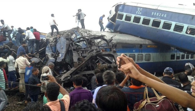
A tremor was followed by a “loud sound like an earthquake”. The carriages began to shake and inside them, passengers began falling on each other. Some carriages telescoped into each other, others rose vertically, “almost standing upright”. In a major train derailment accident, at least 23 passengers were killed and over 60 injured when 14 coaches of the Puri-Haridwar Utkal Express jumped the rails in Khatauli, India at 5.45 pm on19 August 2017 as seen in the figure above. Indian Railways has had the most derailments in a decade in 2016-17: 78 derailments with 193 people dead. On September 14, 2017 (coincidentally my birthday) Indian Prime Minister Narendra Modi and Japanese Prime Minister Shinzo Abe laid the foundation stone for $17 billion bullet train, the Jammu Tawi-New Delhi Rajdhani Express jumped the tracks at New Delhi station, the ninth derailment in 27 days, a consequence of growing traffic, falling safety standards and under investment. Many people say that Indian railways first need to ensure that passengers complete their journeys alive and the money would be better spent upgrading ageing carriages and crumbling tracks. The construction of railways is developing rapidly and the train is going faster and faster, so how to control and prevent derailment of train has become one of the most important task for people working in railways. Train derailments can mainly result in not only financial losses in the form of damaged rolling stock and infrastructure, but also more importantly in causalities and operational shut-down. Therefore, it is crucial for the railway industry to sustain a reliable and efficient operation and eliminate safety concerns. According to the theory of accident causation by Heinrich, behind the seemingly accidental incident is the inevitable rule: to draw a lesson from the accident, and to avoid the similar accident from happening again. Analysis of accidents caused by train derailment is highlighted as one of the most crucial steps in the risk management chain. Considering various operational environment, the analysis enables reduction in the occurrence of derailment and prevents derailments in the most cost-efficient manner, as a variety of different causes and their frequency and severity are determined. A paper written in 2012 analyzing data from the previous decade showed that “broken rails or welds were the leading derailment cause on main, yard, and siding tracks.” Other possible causes can include human error: going too fast, using the wrong track switch, or mistakes with the brakes. Although the railways keep our 21st-century economy running, it’s essentially a 19th-century technology. Rail operators have known for decades that technological fixes could prevent rail disasters but they have been dragging their feet because those fixes are expensive and complicated. I have always preferred train travel to air or road travel but recent epidemic of derailments raises concern in my mind.
______
______
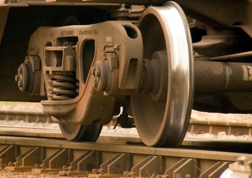
Train wheels on rail track:
_
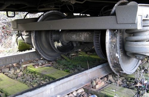
Train wheels off rail track = derailment:
______
______
Abbreviations and synonyms:
Railroad = Railways
Switch = Point = Turnout
Railroad car = railcar = car = wagon = carriage = coach
Bogie = railroad truck = truck = chassis or framework-like structure underneath a train to which axles and wheels are attached through bearings. In India, railway coach is also known as bogie.
Rake = group of coaches or wagons
Locomotive = railway engine
_
C.G. = center of gravity
CWR = Continuous welded rail
SPAD = Signal Passed at Danger
HABD = Hot Axle Box Detectors
RCF = Rolling contact fatigue
RCW = Rolling contact wear
LC = Level crossings
GRS = Guard rail system
LHB = Linke Hofmann Busch
ICF = Integral Coach Factory
PTC = Positive Train Control
AWS = Automatic Warning System
TPWS = Train Protection & Warning System
ATP = Automatic train protection
ACD = Anti-collision device
TCAS = Train Collision Avoidance System
ETCS = European Train Control System
HSR = High speed rail
FRA = Federal Railroad Administration
BG = Broad Gauge
SG = Standard Gauge
MG = Meter Gauge
NG = Narrow Gauge
WSP = Wheel Slide Protection
ACE = Axle Core Electromagnet
______
______
Introduction to railways:
_
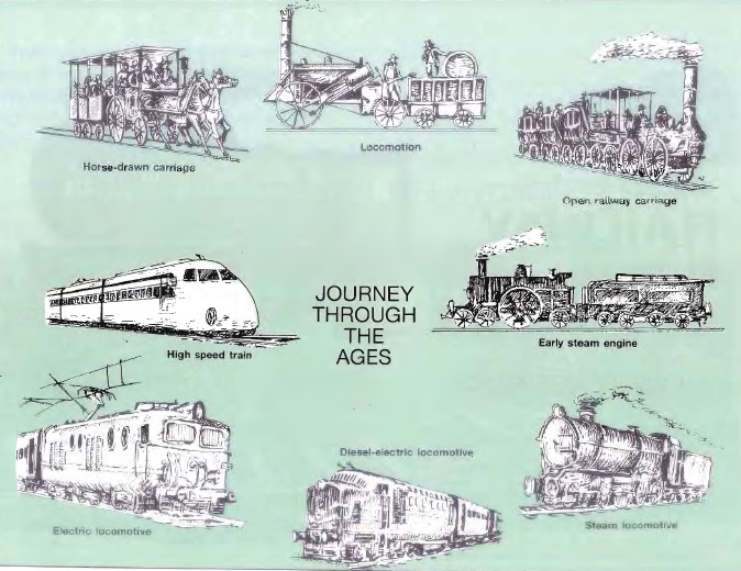
History of railways from horse-driven carriages to high speed train:
_
Chugging across short distances or entire continents, trains act as a major form of transportation worldwide. Also called railroads or railways, trains carry within their cars passengers or freight — such as raw materials, supplies or finished goods — and sometimes both. Before you had limited options for traveling around town and country. Paved roadways didn’t always crisscross the countryside. Even with roads, horse-drawn vehicles still struggled to move people and goods, especially in bad weather. As early as 1550, pragmatic Germans constructed and used wooden railway systems, reasoning that horse-drawn wagons and carts could travel more easily and quickly over wooden rails than dirt roads. By the late 1700s, iron wheels and rails had one-upped wooden ones. But it wasn’t until the steam locomotive was invented in 1797 in England that the railroad as we know it began to take shape. The history of railroading is rooted in the production of the first metal rails near the city of Sheffield, England in 1776. The rail improved the transportation of materials in industries such as mining. In 1803 the first railroad intended for public use was opened for operation between the London docks and Croyden. This first railway, the Surrey Iron Railway, offered a smoother ride than a wagon, but offered no real advantage in speed since draft animals were used for locomotion. However, the first steam locomotive was soon to arrive on the scene. In 1804, a steam locomotive pulled a train of cars carrying several tons of ore for the iron works at Merthyr Tydfil in South Wales. The first American locomotive, the Best Friend of Charleston, was placed in operation on the South Carolina Railroad in 1831. The Stockton & Darlington Railroad Company in England became the first public railroad to carry passengers and freight. Steam-powered locomotives carried six coal cars and up to 450 passengers a distance of 9 miles (14 kilometers) in less than an hour. Horses just couldn’t top that. Across the ocean, the B&O Railroad Company established itself as the first U.S. railroad company in 1827. By 1860, U.S. rail workers had laid more than 30,000 miles (48,280 kilometers) of track, more than in the entire world. Railroads served as the main mode of transportation and made it cheap and easy to ship supplies and goods, even for Union and Confederate armies during the Civil War. After the Civil War, the U.S. railroad network expanded again, and the country’s first transcontinental railway was completed in 1869. Towns sprouted along the railway lines, and the railroad hastened westward expansion. By the early 20th century, U.S. railroads operated 254,000 miles (408,773 kilometers) of track. Diesel locomotives had replaced steam ones. But by the mid-20th century, the decline of the U.S. railroads had begun. A developed interstate highway system and extensive federal regulations took their toll on trains. In the ongoing energy crisis, however, trains, which run on diesel and sometimes even biodiesel fuel, may regain their former popularity with passengers as we move through the 21st century. When we say train, we’re referring to the whole package: railroad cars, railroad track, switches, signals and a locomotive, although not all trains rely on locomotives to pull them, but most of the trains do. With the locomotives leading the way, coupled-together railroad cars follow, filled with freight and passengers. The railroad track steers the train.
____
Figure below shows worldwide rail network density:
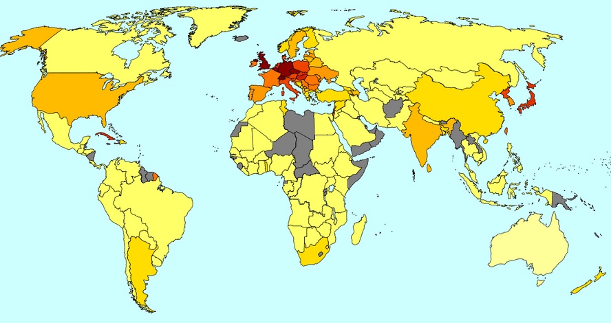
_______
_______
Train:
The railway terminology that is used to describe a train varies between countries.
Rolling stock is any railway vehicle that is not capable of moving under its own power in UK and any railroad car or locomotive in US.
United Kingdom:
In the United Kingdom, the interchangeable terms set and unit are used to refer to a group of permanently or semi-permanently coupled vehicles, such as those of a multiple unit. While when referring to a train made up of a variety of vehicles, or of several sets/units, the term formation is used. (Although the UK public and media often forgo formation, for simply train.) The word rake is also used for a group of coaches or wagons. In the United Kingdom Section 83(1) of the Railways Act 1993 defines “train” as follows:
a) Two or more items of rolling stock coupled together, at least one of which is a locomotive; or
b) A locomotive not coupled to any other rolling stock.
United States:
In the United States, the term consist is used to describe the group of rail vehicles which make up a train. When referring to motive power, consist refers to the group of locomotives powering the train. Similarly, the term trainset refers to a group of rolling stock that is permanently or semi-permanently coupled together to form a unified set of equipment (the term is most often applied to passenger train configurations).
The Atchison, Topeka and Santa Fe Railway’s 1948 operating rules define a train as: “An engine or more than one engine coupled, with or without cars, displaying markers.”
_
A train is a form of rail transport consisting of a series of connected vehicles that usually runs along a rail track to transport cargo or passengers. Motive power is provided by a separate locomotive or individual motors in self-propelled multiple units. Although historically steam propulsion dominated, the most common modern forms are diesel and electric locomotives, the latter supplied by overhead wires or additional rails. Other energy sources include horses, engine or water-driven rope or wire winch, gravity, pneumatics, batteries, and gas turbines. Train tracks usually consist of two parallel running rails, sometimes supplemented by additional rails such as electric conducting rails and rack rails, with a limited number of monorails and maglev guideways in the mix. The word ‘train’ comes from the Old French trahiner, from the Latin trahere ‘pull, draw’.
_
There are various types of trains that are designed for particular purposes. A train may consist of a combination of one or more locomotives and attached railroad cars, or a self-propelled multiple units e.g. Mainline Electric Multiple Unit or MEMU commuter rail system (or occasionally a single or articulated powered coach, called a railcar). The first trains were rope-hauled, gravity powered or pulled by horses. From the early 19th century almost all were powered by steam locomotives. From the 1910s onwards the steam locomotives began to be replaced by less labor-intensive and cleaner (but more complex and expensive) diesel locomotives and electric locomotives, while at about the same time self-propelled multiple unit vehicles of either power system became much more common in passenger service.
_
- Passenger Railroad Systems:
A passenger train is one which includes passenger-carrying vehicles which can often be very long and fast. One notable and growing long-distance train category is high-speed rail (HSR). In order to achieve much faster operation over 500 km/h (310 mph), innovative maglev technology has been researched for years. In most countries, such as the United Kingdom, the distinction between a tramway and a railway is precise and defined in law.
_
Amtrak is the only nationwide passenger railroad system in the United States. Amtrak operates on tracks owned by host railroads. In fact, 70 percent of Amtrak routes are owned by Class I freight companies. It serves more than 500 destinations in 46 states. In 2007, Amtrak carried 25.8 million passengers (average of 70,000 passengers on 300 trains daily). Amtrak receives federal, state and local support in return for offering passenger and commuter services. Despite the government support and increased ridership, Amtrak hasn’t turned a profit. In 2007, Amtrak’s expenses exceeded its revenues by about $1 billion. One potential reason for the shortfall is the fact that Amtrak faces steep competition from automobiles and airlines.
In the United States, passenger rail traffic hasn’t caught on for several reasons:
- The country lacks a passenger rail network that’s independent of the freight railroad system, so not all areas of the country have access to railroads.
- Until recently, the price of oil has still been relatively cheap, which makes automobiles and airlines more desirable modes of transportation for many people.
- Many trains are still relatively slow or make many stops. For example, a train trip from Raleigh, N.C. to Washington, D.C., can take five hours, which is the same amount of time that it takes to drive between these two cities.
However, as oil prices increase, Americans will seek alternative means for long-distance travel, and trains are a good candidate.
In contrast, European railway systems are devoted primarily to passenger traffic. Most European railways are government-owned. In 1959, the Eurail Group was created to handle the increased tourism load. The organization coordinates and markets passenger rail traffic among 30 European countries. The European network connects most European cities. Eurail’s high-speed trains have become competitive with airlines and are more efficient than automobiles. India, Russia, China, Korea, Japan and Australia also offer passenger rail service. Each country has an extensive rail network for passenger travel. Furthermore, the European train network is being linked to railways that travel to China, India and Southeast Asia. However, not all countries or continents have established international rail networks. Neither Africa nor Central or South America boast such networks. And while Mexico, Peru, Brazil, South Africa and Morocco have trains, those trains operate on tracks located solely within those countries.
_
- Freight Railroad Systems:
A freight train (also known as a goods train) uses freight cars (also known as wagons or trucks) to transport goods or materials (cargo). Freight and passengers may be carried in the same train in a mixed consist. Railroads are perhaps the cheapest way to haul freight overland. According to the Association of American Railroads (AAR), the U.S. freight train system leads the world in volume of traffic, amount of freight hauled, revenues, affordability, miles of track and other measures. Freight railroads carry lots of stuff, but the most common item is coal for electrical power plants. Chemicals, farm products, nonmetallic minerals, mixed shipments and other commodities make up the major categories. The success of the U.S. freight railroad system has shown that moving goods by rail can be economical, efficient and profitable. Trains are an essential part of a country’s infrastructure.
_
- Rail cars and machinery used for maintenance and repair of tracks, etc., are termed maintenance of way equipment; these may be assembled into maintenance of way trains. Similarly, dedicated trains may be used to provide support services to stations along a train line, such as garbage or revenue collection.
_
- Light rail:
The term light rail is sometimes used for a modern tram system, but it may also mean an intermediate form between a tram and a train, similar to a heavy rail rapid transit system except that it may have level crossings. Light rail is a city-based rail system based on tram design standards that operates mostly in private rights-of-way separated from other traffic but sometimes, if necessary, mixed with other traffic in city streets. Light rail vehicles (LRV) generally have a top speed of around 55 mph (89 km/h) though mostly operating at much lower speeds, more akin to road vehicles. Light rail vehicles usually run on trackage that weighs less per foot (due to a smaller track profile) than the tracks used for main-line freight trains; thus they are “light rail” due to the smaller rails usually used.
_
Locomotive:
Train engine is the technical name for a locomotive attached to the front of a railway train to haul that train. Alternatively, where facilities exist for push-pull operation, the train engine might be attached to the rear of the train. Traditionally, locomotives pulled trains from the front. However, push-pull operation has become common, where the train may have a locomotive (or locomotives) at the front, at the rear, or at each end. A locomotive or engine is a rail transport vehicle that provides the motive power for a train. A locomotive has no payload capacity of its own, and its sole purpose is to move the train along the tracks. In contrast, some trains have self-propelled payload-carrying vehicles. These are not normally considered locomotives, and may be referred to as multiple units, motor coaches or railcars. The use of these self-propelled vehicles is increasingly common for passenger trains, but rare for freight. Vehicles which provide motive power to haul an unpowered train, but are not generally considered locomotives because they have payload space or are rarely detached from their trains, are known as power cars.
_
As a general rule of thumb, locomotives will generally weigh in at 30-35 tons per axle, with the average 4-axle locomotive around 125 tons and a 6-axle locomotive around 200 tons. The current ‘average’ empty weight of boxcar (goods wagon) varies from 25-30 tons. The payload capacity of that boxcar can vary from 50-70 tons. The average empty Amtrak passenger car weighs about 65 tons.
_
There are three types of locomotive: electric, diesel and steam. The job of the locomotive is to change the chemical energy from the fuel (wood, coal, diesel fuel) into the kinetic energy of motion. The first locomotives did this with a steam engine that lasted for about a century, but was eventually replaced by the diesel locomotive, a mighty mechanical wonder that may consist of a giant engine along with electric alternators or generators to provide electrical power to the train. Many trains intersperse multiple locomotives throughout their lineup to increase and distribute the power. Besides steam- and diesel-powered locomotives, many trains operate solely on electrical power. They get the electricity from a third rail, or electrical line, along the track. Transformers transfer the voltage from the lines, and the electrical current drives the motors (AC or DC) on the wheels. Electrical locomotives are used on subways and many commuter rail systems.
_
Bogie:
A bogie is a wheeled wagon or trolley. In mechanics terms, a bogie is a chassis or framework carrying wheels, attached to a vehicle. It can be fixed in place, as on a cargo truck, mounted on a swivel, as on a railway carriage or locomotive, or sprung as in the suspension of a caterpillar tracked vehicle. Usually, two bogies are fitted to each carriage, wagon or locomotive, one at each end. An alternate configuration often is used in articulated vehicles, which places the bogies (often jacobs bogies) under the connection between the carriages or wagons. Most bogies have two axles, as this is the simplest design, but some cars designed for extremely heavy loads have been built with up to five axles per bogie. Heavy-duty cars may have more than two bogies using span bolsters to equalize the load and connect the bogies to the cars. Usually, the train floor is at a level above the bogies, but the floor of the car may be lower between bogies, such as for a double decker train to increase interior space while staying within height restrictions, or in easy-access, stepless-entry, low-floor trains.
_
All railroad cars have an undercarriage that contains wheels and a suspension system to buffer the ride. On each end of the undercarriage, couplers, which are like hooks, connect the cars.
What’s on top of the undercarriage depends upon the type of railroad car, and there are several.
- A boxcar is a basic box into which crates of goods can be piled up.
- An ore car has an open top and carries coal or other mineral ore such as bauxite.
- A tank car holds liquids, usually chemicals such as chlorine and ammonia.
- Flat cars can hold bulky irregular items on them, such as construction equipment or spools.
- Trailer cars can transport automobiles.
- Container cars are filled with boxed containers of various materials. Often, containers can be double-stacked on these cars.
- Passenger cars, of course, hold people. Some have glass-enclosed viewing areas on top, and some may even be sleeper cars for long trips.
_
Driver or engine driver or operator or engineer:
Driver only operation (DO or DOO) is operation of a train by the engineer or driver only. It is also known as one person train operation (OPTO). Operators control the train by using the throttle, reversing gear and brake. The throttle controls the speed of the locomotive. The reversing gear enables the locomotive to back up. The brake allows the locomotive to slow and stop. Regardless of the type, locomotives use air brakes and hand brakes to stop the engine. Air brakes use high-pressure air to drive the brake foot against the wheel. The friction between the brake pad and the wheels slows the wheels’ motions. The operator also throttles the engine back to slow the train, like when you take your foot off the gas pedal when stopping your car. A mechanical hand brake is also used in case the air brakes fail (usually when there’s insufficient air pressure to drive them).
_
Train operation modes:
Train operation modes may be classified as follow:
- Full Traction mode: In this mode, master controller is kept in full traction position.
- Driving in Allout mode: means full traction up to maximum service speed.
- Cruising mode: In this mode, train is operated with constant speed and develop tractive effort equal to train resistance; hence value of acceleration is zero.
- Coasting Mode: In this mode, no electric energy is supplied to traction motors and energy required to overcome train resistance is supplied from its kinetic energy, which result gradual reduction in train speed.
- Full service brake: In this mode, master controller is kept in full service brake position.
_
Service Brake & Emergency Brake:
Train brake system:’
To stop or slow, trains typically rely on some combination of three braking systems, including dynamic braking, which entails use of the locomotives’ electric motors to dissipate energy; air-braking system, that operates throughout the train; and independent brakes on board of the locomotives. Air brake system uses air pressure to charge air reservoirs (tanks) on each car. Full air pressure signals each car to release the brakes. A reduction or loss of air pressure signals each car to apply its brakes, using the compressed air in its reservoirs. Air operated brakes used hoses connecting all the wagons of a train, so the driver could apply or release the brakes with a single valve in the locomotive.
Modern air brake systems serve two functions:
- The service brake system, which applies and releases the brakes during normal operations, and
- The emergency brake system, which applies the brakes rapidly in the event of a brake pipe failure or an emergency application by the engine operator (generally referred to as the automatic brake). The emergency brake applies considerably more braking force than the full-service brake.
_
Railway signalling:
Railway signalling is a system used to direct railway traffic and keep trains clear of each other at all times. Trains move on fixed rails, making them uniquely susceptible to collision. This susceptibility is exacerbated by the enormous weight and inertia of a train, which make it difficult to quickly stop when encountering an obstacle. Most forms of train control involve movement authority being passed from those responsible for each section of a rail network (e.g., a signalman or stationmaster) to the train crew. The set of rules and the physical equipment used to accomplish this determine what is known as the method of working (UK), method of operation (US) or safeworking (Aus.). Not all these methods require the use of physical signals, and some systems are specific to single track railways.
_
Block signalling:
Trains cannot collide with each other if they are not permitted to occupy the same section of track at the same time, so railway lines are divided into sections known as blocks. In normal circumstances, only one train is permitted in each block at a time. This principle forms the basis of most railway safety systems. Most blocks are “fixed”, i.e. they include the section of track between two fixed points. On timetable, train order, and token-based systems, blocks usually start and end at selected stations. On signalling-based systems, blocks start and end at signals. The lengths of blocks are designed to allow trains to operate as frequently as necessary. A lightly used line might have blocks many kilometres long, but a busy commuter line might have blocks a few hundred metres long.
_
A train is not permitted to enter a block until a signal indicates that the train may proceed, a dispatcher or signalman instructs the driver accordingly, or the driver takes possession of the appropriate token. In most cases, a train cannot enter the block until not only the block itself is clear of trains, but there is also an empty section beyond the end of the block for at least the distance required to stop the train. In signalling-based systems with closely spaced signals, this overlap could be as far as the signal following the one at the end of the section, effectively enforcing a space between trains of two blocks.
_
When calculating the size of the blocks, and therefore the spacing between the signals, the following have to be taken into account:
- Line speed (the maximum permitted speed over the line-section)
- Train speed (the maximum speed of different types of traffic)
- Gradient (to compensate for longer or shorter braking distances)
- The braking characteristics of trains (different types of train, e.g., freight, High-Speed passenger, have different inertial figures)
- Sighting (how far ahead a driver can see a signal)
- Reaction time (of the driver)
Historically, some lines operated so that certain large or high speed trains were signalled under different rules and only given the right of way if two blocks in front of the train were clear.
_
Train detection
The most common way to determine whether a section of line is occupied is by use of a track circuit. The rails at either end of each section are electrically isolated from the next section, and an electrical current is fed to both running rails at one end. A relay at the other end is connected to both rails. When the section is unoccupied, the relay coil completes an electrical circuit, and is energized. However, when a train enters the section, it short-circuits the current in the rails, and the relay is de-energized. This method does not explicitly need to check that the entire train has left the section. If part of the train remains in the section, the track circuit detects that part. This type of circuit detects the absence of trains, both for setting the signal indication and for providing various interlocking functions—for example, preventing points from being moved while a train is approaching them. Electrical circuits also prove that points are locked in the appropriate position before the signal protecting that route can be cleared.
_
Fixed block system and moving block system:
One disadvantage of having fixed blocks is that the faster trains are allowed to run, the longer the stopping distance, and therefore the longer the blocks need to be, thus decreasing the line’s capacity. The fixed blocks must be sized for the worst case stopping distance, regardless of the actual speed of the trains. Under a moving block system, computers calculate a “safe zone” around each moving train that no other train is allowed to enter. The system depends on knowledge of the precise location and speed and direction of each train, which is determined by a combination of several sensors: active and passive markers along the track, and train-borne speedometers; (GPS systems cannot be relied upon because they do not work in tunnels). With a moving block setup, lineside signals are unnecessary, and instructions are passed directly to the trains. This has the advantage of increasing track capacity by allowing trains to run closer together while maintaining the required safety margins.
________
________
List of countries by rail transport network size based on International Union of Railways data:
| Rank | Country | Railway length (km) |
Electrified length (km) |
Area (km2) per km track | Population per km track | Nationalized or Private |
| 1 | United States | 250,000 | <1,600 | 43.71 | 1,373 | Private |
| 2 | China | 124,000 | 80,000 | 77.4 | 11,048 | Nationalized |
| 3 | India | 115,000 | 23,883 | 48.34 | 17,796 | Nationalized |
| 4 | Russia | 86,000 | 50,000 | 198.82 | 1,669 | Nationalized |
| 5 | Canada | 46,552 | 129 | 214.48 | 716 | Private |
| 6 | Germany | 43,468 | 19,973 | 8.22 | 1,881 | Both |
| 7 | Australia | 38,445 | 2,715 | 199.94 | 572 | Both |
| 8 | Brazil | 37,743 | 6,988 | 299.6 | 6,986 | Private |
| 9 | Argentina | 36,966 | 136 | 77.45 | 1,117 | Nationalized |
| 10 | South Africa | 31,000 | 24,800 | 39.39 | 1,742 | Nationalized |
| 11 | France | 29,640 | 15,140 | 21.53 | 2,201 | Nationalized |
__
The United States has the world’s longest railway network, followed by China and India. The US rail network, with an operating route length over 250,000km, is the biggest in the world. Freight lines constitute about 80% of the country’s total rail network, while the total passenger network spans about 35,000km. The US freight rail network consists of 538 railroads (seven Class I railroads, 21 regional railroads, and 510 local railroads) operated by private organisations. Union Pacific Railroad and BNSF Railway are among the largest freight railroad networks in the world. The national passenger rail network Amtrak comprises of more than 30 train routes connecting 500 destinations across 46 American states. Trains carry 40 percent of America’s freight as well as 650 million passengers a year, and in general, their safety record is good and getting better. A plan is in place to build a 27,000km national high speed rail system in four phases by 2030. Construction of the California high-speed rail, the country’s first high-speed rail project, was well underway by the beginning of 2014. Three more high-speed projects including the Midwest high-speed rail line connecting Chicago with Indianapolis or St. Louis, Texas high-speed rail, and the Northeast High-Speed Corridor are under development.
China’s rail network, with a route length of over 124,000km, ranks as the second biggest rail network in the world. The extensive network, operated by state-owned China Railway Corporation, carried 2.08 billion passengers (the second highest after Indian Railways) and 3.22 billion tonnes of freight (the second highest after the US railway network) in 2013. The rapid expansion of China’s high-speed rail network in recent years makes it by far the largest in the world. The 2,298km Beijing – Guangzhou high speed line is the world’s longest high-speed railway line. The total length of China’s high-speed rail network is projected to reach 50,000km by 2020.
The Indian nationwide rail network, the third longest in the world, is owned and operated by state-owned Indian Railways and includes an operating route length of more than 115,000km. The network carried about 8.4 billion passengers (the highest in the world) and 1.01 million tonnes of freight (fourth highest in the world) in 2013. The Indian railway network is divided into 17 zones and operates more than 19,000 trains per day, including 12,000 passenger trains and 7,000 freight trains. Six high-speed corridors have also been identified for implementation in the country. The 534km Mumbai-Ahmedabad high-speed link is being advanced as a pilot project.
_
Countries without railway currently:
- Andorra
- Bhutan
- Cyprus
- Timor-Leste
- Guinea-Bissau
- Iceland
- Kuwait
- Libya
- Macau
- Malta
- Marshall Islands
- Mauritius
- Micronesia
- Niger
- Oman
- Papua New Guinea
- Qatar
- Rwanda
- San Marino
- Solomon Islands
- Somalia
- Suriname
- Tonga
- Trinidad and Tobago
- Tuvalu
- Vanuatu
- Yemen
______
______
Structure and function of railways:
__
Railway track:
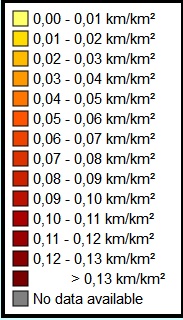
Railroad tracks guide the train, acting as the low-friction surface on which the train runs and often transferring the weight of the train to the ground below. Train tracks help steer the train in the direction it needs to go. Running on tracks allows a train to go faster than other types of ground transportation, like cars.
_
Rails are the members of the track laid in two parallel lines to provide an unchanging, continuous, and level surface for the movement of trains. To be able to withstand high amount of stresses these are made of high carbon steel. A railway track or railway line is a set of two parallel rows of long pieces of steel i.e. rails. They are used by trains to transport people and things from one place to another. Often, there is more than one set of tracks on the railway line. For example, trains go east on one track and west on the other one. The rails are supported by cross pieces set at regular intervals (called sleepers or ties), which spread the high pressure load imposed by the train wheels into the ground. They also maintain the rails at a fixed distance apart (called the gauge). Ties are usually made from either wood or concrete. The rails are usually bolted to the ties. The ties are set into the loose gravel or ballast which is a name for very small pieces of broken up rock that are packed together and keep the railway tracks in place. Ballast help transfer the load to the underlying foundation. The ties “float” on the ballast and the weight of the track keeps them stabilized. Tracks are often made better by ballast tampers.
_
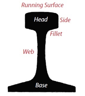
When rail workers are laying train tracks, they often use a flat-bottom steel rail that resembles the steel I-beam girders of construction. The rail has a wide base or foot, a narrow web and a head (wider than the web, but not as wide as the foot). The weights of the rails vary from 80 to 160 pounds (36 to 73 kilograms) per yard depending upon the type of train operating on the tracks and the country. Segments of rail track may connect to one another by bolted plates called fishplates, but most modern rail segments are welded together to provide a smooth ride. The rails are inclined slightly towards each other, typically on a slope of 1 in 20, and the rims of the train wheels are angled in the same way (“coning”). This helps guide the vehicles of the train along the track. Each wheel also has a flange, which sticks out from one edge all the way around. This makes sure the train does not “derail” (come off the track) and helps guide the train on sharp curves. Tracks where electric trains or electric trams run are equipped with an electrification system such as an overhead electrical power line or an additional electrified rail i.e. third rail.
_
Steel tracks can be straight or curved to steer the train since steel is easily bent into shape. Depending upon the topography, some curves may be slightly angled or banked to help the train stay on the track as it negotiates the curve. At various points along the track, rails may have switches, which can move a train from one track to another. Switches and accompanying track are important for controlling traffic. For example, when two trains are operating on the same track, a switch can allow one train to pull off to a holding track while the other one passes. A switch also can change a train’s direction like moving it from a north-south track to an east-west one. Many railroad stations have switching yards where trains are assembled and moved onto various tracks. Finally, signals along the tracks keep the train operators informed of traffic conditions ahead. Signals control train traffic much like traffic lights control automobile traffic on roads. Besides signals, many locomotives have radios and computer terminals that monitor traffic conditions using information supplied by signalling centers, which are similar to air traffic control stations.
_____
_____
Rails:
Early rails were made of wood, cast iron or wrought iron. All modern rails are hot rolled steel with a cross section (profile) approximate to an I-beam, but asymmetric about a horizontal axis. The head is profiled to resist wear and to give a good ride, and the foot profiled to suit the fixing system. Unlike some other uses of iron and steel, railway rails are subject to very high stresses and are made of very high quality steel. It took many decades to improve the quality of the materials, including the change from iron to steel. Minor flaws in the steel that may pose no problems in other applications can lead to broken rails and dangerous derailments when used on railway tracks. By and large, the heavier the rails and the rest of the trackwork, the heavier and faster the trains these tracks can carry. Rails represent a substantial fraction of the cost of a railway line. Only a small number of rail sizes are made by steelworks at one time, so a railway must choose the nearest suitable size. Worn, heavy rail from a mainline is often reclaimed and downgraded for re-use on a branchline, siding or yard.
_
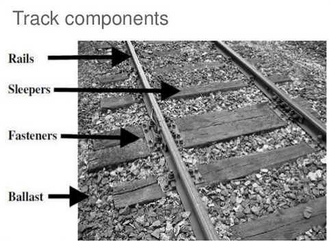
Rail development:
The rails have evolved from cast iron plates to specially alloyed steels, which are rolled to a standard shape and specially heat-treated to obtain the desired properties. The figures above show the progression of rail development. Present day steel rails are vastly superior to their predecessors in both strength and wear qualities, however defects still develop. The heavy loads and high speed of today’s trains can cause rails to fail in service unless regular inspections are performed.
_
The earliest aspects of railroad infrastructure are, of course, the track and roadbed. Railroad track, as with railroading itself, has its roots in England where for years coal mines had been using horses or mules to pull carts that used flanged wheels to operate on wooden or strap-iron rails (which was essentially a wooden rail with a piece of flat iron attached to the top). This type of track remained in use as late as the 1840s (by this point strap-rail was the norm) until solid iron “T”-rail was developed by Robert Stevens, president of the Camden & Amboy Railroad, it was a revolutionary design still used to this day. The unstable and dangerous strap-rail (which was simply thin pieces of iron attached to wooden planks) that caused the deadly phenomenon of “snake heads” (which was an iron strap that came loose and was peeled upward by a passing car wheel and it acted as a can opener when the next train passed over the broken rail literally ripping the train apart and almost always killing passengers and sometimes crewmen) was replaced by solid iron ‘T’ rails. Today ‘T’ rail is replaced with ‘I’ rail.
_
Rail profile:
The rail profile is the cross sectional shape of a railway rail, perpendicular to its length.
_
Why do a rails have a particular shape like I?
These are shaped so for following purposes:
- The top portion or the HEAD of the rail is thicker to take up the impact of the fast moving wheels, and carry the load of trains preventing abrasion of the tracks.
- The WEB of the rail is to uplift the train from the ground level; and to provide clear cover (distance) between wheel base plus flanges and the sleeper/ ballast layer.
- The FOOT provides two-fold purpose. Easy clamping i.e. fixing to the sleeper beneath it because of wider area as well as greater surface area helps in load transfer to the sleeper more efficiently which further transfers the load to ballast and later sub-base.
Upper half should be wide enough to support the wheel and lower half should be wide & thick enough for clamping. Taking out extra materials saves significant amount of iron without compromising over strength thus giving it ‘I’ shape. It has to be symmetrical so that it can be used on the left and the right track.
The usual, Flat Footed rails used for Broad Gauge lines is shown below with its components. This is typical shape of the cross-section of a track laid with Flat-footed Rails. The Bull headed rails resemble the ‘I’ shape more correctly.
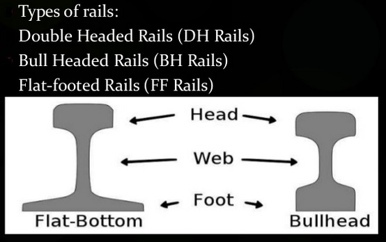
Types of rails:
- Double Headed Rails (DH Rails)
- Bull Headed Rails (BH Rails)
- Flat-footed Rails (FF Rails)
_
Rail weights and sizes:
Two commonly used rail profiles: a heavily worn 50-kg/m profile and a new 60-kg/m profile. The weight of a rail per length is an important factor in determining rails strength and hence axleloads and speeds. Weights are measured in pounds per yard or kilograms per metre; the pounds-per-yard figure is almost exactly double the kilograms-per-metre figure. Rails in Canada, the United Kingdom and United States are described using imperial units. In Australia, metric units are used as in mainland Europe. Commonly, in rail terminology Pound is a contraction of the expression pounds per yard and hence a 132–pound rail means a rail of 132 pounds per yard.
Rails are made in a large number of different sizes. Some common European rail sizes include:
- 40 kg/m (81 lb/yd)
- 50 kg/m (101 lb/yd)
- 54 kg/m (109 lb/yd)
- 56 kg/m (113 lb/yd)
- 60 kg/m (121 lb/yd)
In the countries of former USSR 65 kg/m (131 lb/yd) rails and 75 kg/m (150 lb/yd) rails (not thermally hardened) are common. Thermally hardened 75 kg/m (150 lb/yd) rails also have been used on heavy-duty railroads like Baikal–Amur Mainline, but have proven themselves deficient in operation and were mainly rejected in favor of 65 kg/m (131 lb/yd) rails.
_
Rail gauge:
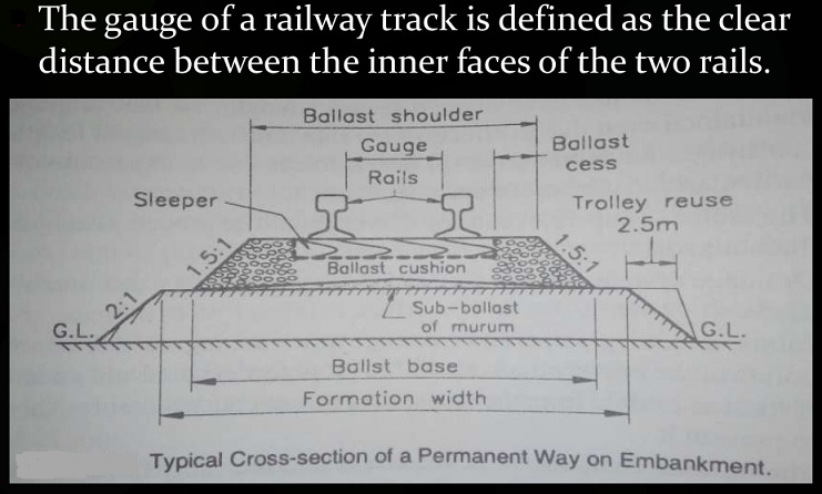
The gauge of a railway track is defined as the clear distance between the inner faces of the two rails.
Dimension of gauges
- Broad Gauge (BG) 1676mm (5’6”)
- Standard Gauge (SG) 1435mm
- Meter Gauge (MG) 1000mm
- Narrow Gauge (NG) 762mm (2’6”)
- Light Gauge 610mm
Broad gauge is where the rails are spaced more widely apart than 1,435 mm (4 ft 8 1⁄2 in) which is called standard gauge. Many early railroads were broad gauge, for example the Great Western Railway in the UK which adopted 7 ft (2,134 mm) gauge until it was converted to standard gauge in the 1860s – 1890s. Russia still has over 80,000 km (50,000 mi) of broad gauge [1,520 mm (4 ft 11 27⁄32 in)] railroads. Broad gauge is also normal in Spain and Portugal [1,668 mm (5 ft 5 21⁄32 in)], in India and Sri Lanka [1,676 mm (5 ft 6 in)], as well as Ireland and used in some parts of Australia [1,600 mm (5 ft 3 in)].
_
Height and width of rails:
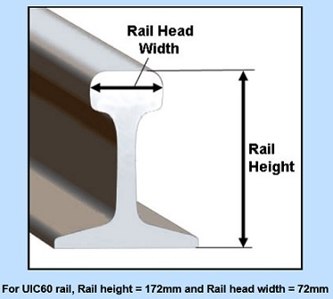
_
Length of Rails:
Rails should be made as long as possible since joints between rail lengths are a source of weakness. As manufacturing processes have improved, rail lengths have increased. Long rails are flexible, and there is no problem going around curves.
On Indian Railways the standard lengths are the following: Length = 12.80 m. (42 ft.) for BG and Length = 11.9 m. (39 ft.) for MG
Length = 39 feet (11.9 m) in United States and 60 feet (18.3 m) in London and North Western Railway (UK).
_
Weight and section of rail are governed by many factors:
- Gauge of track
- Max. Permissible speed
- Type and spacing of sleepers
- Depth of ballast cushion
- Heaviest moving load likely to cross over the rail
- Spacing of sleepers
_
Maximum axle load that can be carried by a rail depends on its weight:
In India the capacity will be calculated as follows:
Max axle load = 560 X sectional weight of rail in kg/m
For 52 kg rail, max. axle load = 560 X 52 = 29.12 tonnes
_
Track Geometry Parameters:
- Surface (left, right)
- Cross-level (super-elevation)
- Twist (warp)
- Alignment (left, right)
- Curvature
- Gauge
______
Functions of Rails:
Rails are similar to steel girders. These are provided to perform the following functions in a track.
- Rails provide a continuous and level surface for the movement of trains.
- Rails provide a pathway which is smooth and has very little friction.
- Rails serve as a lateral guide for the wheels.
- Rails bear the stresses developed due to vertical loads transmitted to them through axles and wheels of rolling stock as well as due to braking and thermal forces.
- Rails carry out the function of transmitting the load to a large area of the formation through sleepers and the ballast.
_______
Requirements of Ideal rail:
- The section of the rail should be such that the load of each wheel is transferred to the sleepers without exceeding the permissible stresses
- The section of the rail should be able to withstand the lateral forces caused due to fast moving trains.
- The bottom of head and top of foot should be given such shapes that fishplates can be easily fitted.
- The centre of gravity of the rail section should preferably coincide the centre of the height of the rail so that maximum tensile and compressive stresses are nearly equal.
- The web of the rail section should be such that it can safely bear the vertical load without buckling.
- The head of the rail should be sufficiently thick for adequate margin of vertical wear.
- The foot of rail should provide sufficient bearing area on the underlying sleepers so that the compressive stresses on the timber sleeper remain within permissible limits.
- The section of the rails should be such that the ends of two adjacent rails can be efficiently jointed with a pair of fish plates.
- The surfaces for rail table and gauge face should be sufficiently hard to resist the wear.
- The contact area between the rail and wheel flange should be as large as possible to reduce the contact stresses.
- The specimen of rail should be able to withstand the blow of a falling weight in the test specified by the specifications
- The composition of the steel should conform to the specifications adopted for its manufacture by Open Hearth of Duplex Process
- The overall height of the rail should be adequate to provide sufficient stiffness and strength as a simply supported beam.
- The foot of the rail should be wide enough so that the rail is stable against overturning.
- There should be balanced distribution of metal in head, web and foot.
_____
Joining rails:
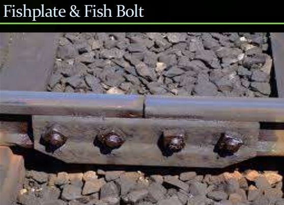
Rails are produced in fixed lengths and need to be joined end-to-end to make a continuous surface on which trains may run. Jointed track is made using lengths of rail, usually around 20 m (66 ft) long (in the UK) and 39 or 78 ft (12 or 24 m) long (in North America), bolted together using perforated steel plates known as fishplates (UK) or joint bars (North America). Fishplates are usually 600 mm (2 ft) long, used in pairs on either side of the rail ends and bolted together (usually four, but sometimes six bolts per joint). The bolts may be oppositely-oriented so that in the event of a derailment and a wheel flange striking the joint, only some of the bolts will be sheared, reducing the likelihood of the rails misaligning with each other and exacerbating the seriousness of the derailment. This technique is not applied universally, European practice being to have all the bolt heads on the same side of the rail. Small gaps which function as expansion joints are deliberately left between the rail ends to allow for expansion of the rails in hot weather. If these gaps are not left then the tracks might have enormous stress in them while expanding due to heat which can cause buckling of rails and derailment. European practice was to have the rail joints on both rails adjacent to each other, while North American practice is to stagger them. Because of the small gaps left between the rails, when trains pass over jointed tracks they make a “clickety-clack” sound. Unless it is well-maintained, jointed track does not have the ride quality of welded rail and is less desirable for high speed trains. However, jointed track is still used in many countries on lower speed lines and sidings, and is used extensively in poorer countries due to the lower construction cost and the simpler equipment required for its installation and maintenance. A major problem of jointed track is cracking around the bolt holes, which can lead to breaking of the rail head (the running surface). This was the cause of the Hither Green rail crash which caused British Railways to begin converting much of its track to continuous welded rail. So for more modern usage, particularly where higher speeds are required, the lengths of rail are welded together to form continuous welded rail (CWR).
_
Continuous welded rail (CWR):
Throughout most of the 19th century iron was the primary choice for railroad track and every other structure being built. However, in the 1890s the much stronger and durable steel was introduced. Steel was not only much stronger than iron but because it had a longer lifespan railroads were willing to pay a little more for it as in the end it meant an improved bottom line. It was not until the 1950s that railroad track would see another major change. That decade saw the first use of continuous welded rail (CWR), also known as ribbon rail, which is laid in lengths of 1,500 feet or so (roughly a 1/4-mile), rather than 39-foot track bolted together. Aside from saving railroads millions in maintenance costs and derailments, CWR does not buckle, because it resists thermal expansion and contraction. Once the benefits of CWR were realized the industry quickly began replacing its most heavily trafficked main lines with the new type of railroad track and by the 1970s most of these routes employed it. Even better for railroads was the fact that CWR did not necessarily have to be purchased new. If a rail line already contained the desired track weight (such as 100, 110, or 120-pound rail) it could simply be welded into strings and relaid costing only the maintenance time required.
_
The advantages to be gained from the use of CWR made its adoption almost inevitable once its practicability was established. Apart from the more comfortable ride for passengers these advantages included economic ones, such as an extension of rail life by between 30 per cent and 40 per cent, savings in the cost of track maintenance, extended sleeper life, and reduction in fuel costs and wear and tear on rolling stock, as well as the important gain in safety resulting from the elimination of rail joints. The latter have always been the weakest point in conventional jointed track and by far the greatest number of rail breaks, and those potentially the most dangerous, have been associated with the fishbolt holes at rail ends. The one drawback to CWR is its tendency to kink, or turn into spaghetti, during the high heat of summer. Known as sun kinks this phenomenon can result in either slow orders or the movements to be suspended entirely until the night or late evening when cooler temperatures allow the track to settle back into place. However, warm temperatures are needed when installing CWR as doing so in cold weather when the steel tends to contract can result in buckling and warping when warmer weather prevails. CWR has become a science into itself as railroads must make sure they install the rail correctly and in warm enough temperatures to keep kinking from occurring.
_______
Railroad tie/sleeper:
_
A railroad tie/railway tie/crosstie (North America) or railway sleeper (British Isles, Australasia, and Africa) is a rectangular support for the rails in railroad tracks. Generally laid perpendicular to the rails, transverse ties are laid to support the rails. They transmit wheel load from the rails to the ballast and subgrade, hold the rails upright and keep them spaced to the correct gauge. Railroad ties are traditionally made of wood, but pre-stressed concrete is now also widely used, especially in Europe and Asia. Steel ties are common on secondary lines in the UK; plastic composite ties are also employed, although far less than wood or concrete. As of January 2008, the approximate market share in North America for traditional wood ties was 91.5%, the remainder being concrete, steel, azobé (red ironwood) and plastic composite. Approximately 3,520 wooden crossties are used per mile of mainline railroad track in the US (distance between ties is nominally 18″ including one tie and the crib), 2,640 per mile (30 per 60 ft rail) on main lines in the UK. Rails in the US may be fastened to the tie by a railroad spike; iron/steel baseplates screwed to the tie and secured to the rail by a proprietary fastening system such as a Vossloh or Pandrol are commonly used in Europe.
_
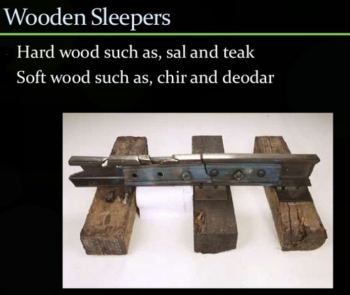
Classification of sleepers/ties:
(i) Wooden sleeper
(ii) Metal sleeper, Cast iron sleeper, Steel sleeper
(iii) Concrete sleeper, Reinforced concrete Sleeper (R.C.C), Prestressed Concrete Sleeper
_
Railroad ties, also known as crossties or sleepers are the primary lateral support for the rails themselves, anchoring the track and giving it a solid, sound base upon which trains can pass over. Throughout the years crosstie technology has improved to the point that today, the common hardwood tie which has been properly treated with creosote can last at least 30-40 years before needing replaced. While the basic design and function of the tie has not changed much in more than a century, today’s technologies have allowed other materials to be utilized notably concrete and even plastics/composites that generally enhance its livelihood. In any event, while railroads have employed these new ties in some instances, especially concrete on heavily used main lines, wood remains the preferred choice due to its cost and generally-good life expectancy.
_
Today ties have a uniform size and thickness, usually at least 8-10 inches thick and about 8-10 feet in length, depending on what they are being used for (i.e., for switch outs or along a main line). There are also important components that hold railroad ties firmly to the rails. The most common of these in the simple spike, which is a basic anchor that is driven into the tie. However, there is also the tie plate, in which the spikes are driven into. This component not only provides a place to drive the spikes but also as a means of housing the rail and helping to distribute the weight over a broader area of the tie itself. Finally, there is the rail anchor. This component simply keeps the rails from shifting north and south as the train passes over. With the ballast the entire track infrastructure is complete providing for a strong, yet flexible operating surface. Today railroad ties are mass produced and are still most often of hardwood although with concrete’s added benefit of allowing for faster and heavier trains it is also becoming a top choice, particularly overseas and in Europe where passenger trains dominate. The one drawback to concrete is that because of its rigid qualities it does not have the same flexibility as wood, or even composite ties. However, its inherent strengths and longevity, even over wood, more than make up for its primary weakness as in the future you will almost surely see more and more main lines employing concrete ties.
______
Ballast:
Ballast (usually crushed stone), as it is known, is another important part of railroad infrastructure. Although it may just look like plain ole gravel this stone plays a vital role in acting as a support base for the railroad ties and rails as well as allowing for proper drainage of water away from the rails (which is why the stone is always sloped downward and away from track). You may be wondering how such a term came to define the stone which supports the railroad track structure. Interestingly, it has its roots dating back to early times when stone was used as ballasting for sailing ships. In today’s railroad industry the use of ballast, its application, and purpose has changed little since it was first employed and will likely always remain an important component as a part of the track structure. According to Brian Solomon’s book Railway Maintenance, The Men and Machines That Keep the Railroads Running, today the typical layout for a well-ballasted railroad track system is stone lined to the top of the railroad ties protruding roughly 14 inches to either side, tapering away on a “3-to-1” slope to an eventual distance of 9 feet, 10 inches from the center-of-track with the stone being about one-foot deep below the bottom of the ties.
_
These stones (called track ballast) serve four primary purposes:
- Load-bearing (it distributes and bears the weight of the railroad ties)
- Facilitation of water drainage away from the ties
- Keeps out vegetation that could interfere with the structure of the track
- Helps keep the ties in place
_
Ballast must regularly be cleaned or added as when dirt and grime builds up within the rock it reduces its ability to properly drain water. Ballast also acts as a support base for the railroad track structure giving it strength and rigidity but also allowing for flexibility when trains pass over. Limestone or quartz is often most used as ballasting because it is a hard stone that will lock together providing for extra strength. According to Brian Solomon’s book Railway Maintenance, The Men and Machines That Keep the Railroads Running, today’s trains can exert a force of 100 psi when passing over track and the stone used for ballasting must be able to withstand this constant abuse.
_
Optimum ballast gradation:
The ballast that is seen under the railway tracks in India are mostly prepared by crushing locally available rocks to generate specific-sized stones. In India, stones measuring 20 mm to 65 mm are permitted to be used as ballast. These sizes are slightly bigger than in many other countries, where even 9 mm ballast is used. The ballast has to fulfil two key objectives. They must have high shear strength to provide maximum stability and minimum track deformation. And, they must have high permeability to allow adequate drainage of water from the tracks in the rainy season. The size of ballast is also referred to as ballast gradation. Now, ballast of larger sizes does not allow for very tight packing; the void is large. This is good for the drainage function, but not ideal for providing maximum stability to the tracks. Because of the loose packing and presence of large voids, when load is applied on the ballast, for example, by a running train, it tries to rearrange itself. In the process, many of the stones break, parts of them getting converted into small granules. Besides these granules, there are also several foreign materials that get mixed into the ballast due to various processes. The trains, for example, carry coal or iron ore. Some of these drop from the wagons and get mixed with the ballast. Dust and mud, and a variety of other materials such as plastics and soil, too, settle in. This is called ballast fouling. Initially, this fouling leads to filling up the voids and helps in packing the ballast tightly. But with time, it starts to create problems. It facilitates the movement of the ballast and makes it easier for the sleepers to shift. This in turn can change the delicate alignment of the rails in the track, which can lead to a derailment. To deal with a problem like this, Indian Railways has to periodically carry out what is called deep-screening of the tracks. In this process, the tracks are lifted and the fouling is cleaned before replacing the tracks. This exercise, as of now, is randomly carried out. Prof Anbazhagan P and his team at the department of civil engineering at the Indian Institute of Science, Bangalore, have now tried to develop a method through which it would be possible to identify the tracks that need immediate deep-screening by studying the nature and extent of ballast fouling. The team has defined an “optimum” fouling point and “critical” fouling point to check state of fouling in the track. If the ballast has reached “optimum” fouling point, deep-screening is recommended immediately. If “critical” fouling point is reached, a track must not be used until it is deep-screened. Anbazhagan says his current research is to focus to define the “optimum” ballast gradation that would be the best suited for performing both the functions of allowing drainage and providing stability to the tracks. Many countries have already defined this “optimum” gradation for their own railway lines. He says these studies can be useful for the existing railway system and future high speed rails.
_
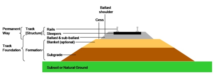
One often forgotten aspect of the ballasting system is what is known as sub-ballast or sub-grade. This layer of crushed stone or even pavement, as some railroads today now use acts as a moister barrier and added support system for the railroad track structure above (including the rails, ties, and ballast). It is always the first component of the track structure to be laid down and is a very important, unseen component. If the railroad track did not have a sub-ballasting system, or very poor one at best, the rails and railroad ties would eventually become water-logged and fail (causing a derailment, or worse, a washout).
_
The figure below shows profile of rail-track-ballast system:
_
Slab track (or ballastless track) would be preferable over ballast any day. It is basically track fixed directly to reinforced concrete slabs and has the advantage of increased stability and lower maintenance costs. It is however expensive, so sleepers and ballast are used instead. In some countries, slab track is used extensively on high speed, high frequency lines, such as Japan or around some areas where the track must be stable such as in tunnels or around stations. This is of course dependant on the amount of investment in rail infrastructure.
______
In the United States, the Federal Railroad Administration has developed a system of classification for track quality. The class of a section of track determines the maximum possible running speed limits and the ability to run passenger trains. The quality of railroad track is commonly divided into nine principal classes by FRA on the basis of track structure, track geometry, and inspection frequency and method. The higher the track class, the more stringent are the track safety standards and thus a higher maximum train speed is allowed.
| Track type | Freight train | Passenger train |
| Excepted | <10 mph (16 km/h) | not allowed |
| Class 1 | 10 mph (16 km/h) | 15 mph (24 km/h) |
| Class 2 | 25 mph (40 km/h) | 30 mph (48 km/h) |
| Class 3 | 40 mph (64 km/h) | 60 mph (97 km/h) |
| Class 4 | 60 mph (97 km/h) | 80 mph (129 km/h) |
| Class 5 | 80 mph (129 km/h) | 90 mph (145 km/h) |
| Class 6 | 110 mph (177 km/h) | |
| Class 7 | 125 mph (201 km/h) | |
| Class 8 | 160 mph (257 km/h) | |
| Class 9 | 220 mph (354 km/h). | |
_______
Note:
On a straight track, there is no outer rail and inner rail. When a track is curved to right, as you enter the curve, rail on right side is inner rail and rail on left side is outer rail. When a track is curved to left, as you enter the curve, rail on right side is outer rail and rail on left side is inner rail. The same terminology for right and left wheel.
______
______
Wheels:
_
A train wheel or rail wheel is a type of wheel specially designed for use on rail tracks. A rolling component is typically pressed onto an axle and mounted directly on a rail car or locomotive or indirectly on a bogie (UK), also called a truck (North America). Wheels are cast or forged (wrought) and are heat-treated to have a specific hardness. New wheels are trued, using a lathe, to a specific profile before being pressed onto an axle. All wheel profiles need to be periodically monitored to ensure proper wheel-rail interface. Improperly trued wheels increase rolling resistance, reduce energy efficiency and may create unsafe operation. A railroad wheel typically consists of two main parts: the wheel itself, and the tire (or tyre) around the outside. A rail tire is usually made from steel, and is typically heated and pressed onto the wheel, where it remains firmly as it shrinks and cools. Monobloc wheels do not have encircling tires, while resilient rail wheels have a resilient material, such as rubber, between the wheel and tire.
_
The wheels of train perform the following three functions:
- The generic function of wheel i.e. carrying the car-body of the train.
- Prevention of derailment by incorporating flanges.
- Differential [vide infra].
_
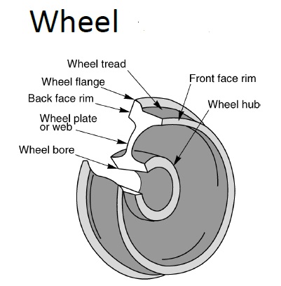
Wheel flange:
Flange is the inner section of a wheel that rides between the two rails. The angle between the wheel tread and flange is often specific to the rail to prevent wheel climb and possible derailments. The wheel flange is part of the wheel tire.
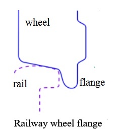
Most train wheels have a conical geometry, which is the primary means of keeping the train’s motion aligned with the track. Train wheels have a flange on one side to keep the wheels, and hence the train, running on the rails, when the limits of the geometry based alignment are reached, e.g. due to some emergency or defect. Some wheels have a cylindrical geometry, where flanges are essential to keep the train on the rail track.
_
Wheel tread:
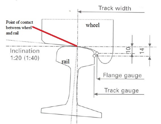
It is the slightly conical section (often with a 1 in 20 slope) of a railroad wheel that is the primary contact point with the rail.
_
Coning of Wheels:
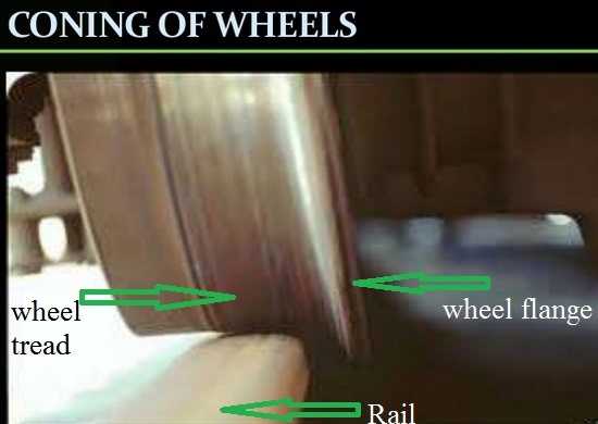
Wheel tread is present in the shape of cone with a slope of 1 in 20. When wheel are moving on track there is a chance of lateral movement. Without coning it will cause a sudden impact on the sides of rails. Coning of wheels is mainly done to maintain the vehicle in the central position w.r.t to the track. Due to coning of wheels, smooth riding possible, but the pressure on the inner edge may cause its wearing. Gauge widening happens sometimes. If base plates are not provided, sleepers under outer rails may damage. To minimize these effects, tilting of rails is done by the use of inclined base plates.
_
Wheel-rail interface:
It is the on-contact interaction between wheels and rails. The term is used in connection with the design and management of their interaction.
_
The most basic wheel:
- Coned wheel – 1/20 to 1/40
- Angular velocity constant for both discs
- Flanged wheel: flange on inside
- 7-10 mm flange clearance
- Single piece or tire-on-disc
- Made of steel by casting or forging
_
Role of conicity + constant angular velocity:
- Provides guidance on straight tracks
- Mechanism of motion gives rise to oscillation
- Differential action on curved tracks
- Easy manufacturing by casting
_
Role of inside flange:
- Final restraint on curves/unusuals
- Gives guidance on curves and changing tracks
- Stability through gravitational stiffness
_
Wheel failure zones:
Thermal cracks: Tread, Plate
Surface contact/rolling contact fatigue/spalling: Tread
Loose wheel: Hub, Bore
Excessive wear: Flange, tread
_
Wheel failure:
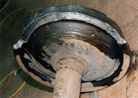
The most common type of wheel failure that may cause derailment is various out of roundness failures such as wheel flats, wheel tread wear and shelling, oval wheels, wheel profile failure etc. By themselves they seldom cause derailments, but wheel flats, wheel tread failures and out of roundness of wheels may increase the load on the bearing whilst wheel flats may also rupture rails, in particular under cold weather conditions. Wheel profile failures in combination with difficult track geometry are a common contributor to derailments. Wheel failures are much more pronounced in cold weather.
_
What would cause a steel wheel to wear out?
Many of the same things that damage car tires: Sudden stops. Sweeping curves. Lots of miles. While many of us change our car tires every 20,000 miles or so, Metro rail wheels can travel as far as 700,000 miles before they need to be replaced. Good thing because changing the wheels on a single rail car can take more than a week, depending on the design of the car. Re-profiling a steel wheel is the process of removing a thin layer of the wheel tread and flange with a large “wheel truing” machine. The truing machine restores the wheel’s roundness, tread taper and flange thickness to create good ride quality and steering.
_______
_______
Physics of train motion:
_
Train Resistance:
Train resistance is the force resisting the motion of train on track. When the tractive force developed by train is greater than the train resistance, then the train will start to accelerate. Specific resistance is equivalent to the train resistance per tonne i.e. train resistance / weight of train. The resistance offered by a train to move from stop is called Starting Train Resistance. The resistance offered by it to keep it moving at a specified speed is known as Rolling Train Resistance. In other words force needed to start a train from stationary position is starting resistance and force needed to keep a train moving at certain speed is rolling resistance. Starting resistance, appears at the time of starting, is to overcome the non-elastic effects of track & wheel surface, inertia and bearing friction. Starting Resistance depend upon the type of bearings, weight per axle & temperature of the bearing and drops rapidly as the train speed increases. It may be noted that the entire train does not start at a time. There is always some slackness in the coupling and by pushing the train backward, all the coupler are brought in slack position. While pulling in such condition, the entire train starts one by one with tightening of the couplers. There is no derived formula for starting resistance. Based on the different measurements, empirically Train and Loco Resistance are taken as 4 and 6 kg/tonne. Starting resistance is generally not much of a problem with the very large tractive effort available with modern diesel locomotives, except on steeper grades.
_
On straight & level track, train resistance consist of following resistances:
- Friction Resistance a.k.a. starting resistance
- Rolling Resistance
- Air Resistance
____
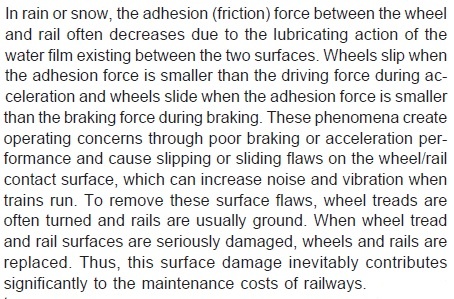
Rail adhesion:
Rail adhesion relies on the friction between a steel wheel and a steel rail. Adhesion is one of the most important term used in Railways parlance signifying the ability of efficient heavy haul and safe braking. Adhesion is caused by friction. Available adhesion between the driving wheels and the track depends on the weight per wheel, irregularities of contact surfaces, environmental conditions etc. and determine the force that can be applied before the wheels begin to slip or slide during traction or braking respectively. Adhesion limits the tractive and braking effort per traction and braking wheel respectively. Friction can be reduced when the rails are greasy, because of rain, oil or decomposing leaves which compact into a hard slippery lignin coating. The slipping and sliding phenomena are about stability in the front-rear direction. The stability in the left-right direction is guaranteed by the shape of the wheels. Adhesive percentage is defined as ratio expressed in percentage of tractive effort at wheel slip and vertical load on driving wheels.
_
Less friction = poor adhesion = wheels slide in braking (long min stopping distance)
Less friction = poor adhesion = wheels slip in traction (loss of hauling capacity)
_
Adhesion is caused by friction, with maximum tangential force produced by a driving wheel before slipping given by:
Fmax= coefficient of friction X Weight on wheel
For steel on steel, the coefficient of static friction can be as high as 0.78, under laboratory conditions, but typically on railways it is between 0.35 and 0.5, whilst under extreme conditions it can fall to as low as 0.05. Thus a 100-tonne locomotive could have a tractive effort of 350 kilonewtons, under the ideal conditions (assuming sufficient force can be produced by the engine), falling to a 50 kilonewtons under the worst conditions.
_
The coefficient of friction is not always the same for objects that are motionless and objects that are in motion; motionless objects often experience more friction than moving ones, requiring more force to put them in motion than to sustain them in motion.
- The static coefficient of friction is the coefficient of friction that applies to objects that are motionless.
- The kinetic or sliding coefficient of friction is the coefficient of friction that applies to objects that are in motion.
- Rolling coefficient of friction is different than sliding coefficient of friction.
__
Factors effecting adhesion:
- Condition of rail and wheel contact surface e.g. wet, dry. oily, slippery, etc.
- Type of track and sleeper density
- Rate of increase in torque applied to wheel.
_
Wheel slip:
Slipping happens when the force applied to move the wheels is larger than the friction between the wheel and the rails which can be resisted. Friction is needed to stop the wheel from slipping. The greatest effort is required from a locomotive when starting. At this time, if the engineer applies too much power to the wheels (i.e., for a steam locomotive, he opens the regulator too far) the turning force applied to the wheel will greatly exceed the opposing friction force affected by the surface of the rail, and the wheel will turn without being able to move the train forward. Wheel slip is not that bad a phenomena, it is speculated that maximum tractive effort during startup is obtained with a certain amount of wheel slip. Thus controllers have been designed for trains to monitor for wheel slip which permits a certain amount of slipping after which power to the wheels is automatically reduced. For Russian trains climbing up a grade, this slip is normally 1.5% to 2.5%. Slip (also known as creep) is normally roughly directly proportional to tractive effort. An exception is if the tractive effort is so high that the wheel is close to substantial slipping (more than just a few percent), then slip rapidly increases with tractive effort and is no longer linear. With a little higher applied tractive effort the wheel spins out of control and the adhesion drops resulting in the wheel spinning even faster. This is the type of slipping that is observable by eye—the slip of say 2% for traction is only observed by instruments. Such rapid slip due to a slippery rail reduces the tractive effort and hence haulage capacity and damages rail and wheel. Wheel slip was common with steam engines as they started to move due to the excessive torque often generated at low speed. Steam engines carried sand dispensing gear to increase traction at the start of motion.
Method to improve adhesion: – Clean rails regularly – Use sand while starting – Immediately cut off power if wheels slip.
__
Creep:
The behaviour of adhesion railways is determined by the forces arising between two surfaces in contact. This may appear trivially simple from a superficial glance but it becomes extremely complex when studied to the depth necessary to predict useful results. The first error to address is the assumption that wheels are round. A glance at the tyres of a parked car will immediately show that this is not true: the region in contact with the road is noticeably flattened, so that the wheel and road conform to each other over a region of contact. If this were not the case, the contact stress of a load being transferred through a point contact would be infinite. Rails and railway wheels are much stiffer than pneumatic tyres and tarmac but the same distortion takes place at the region of contact. Typically, the area of contact is elliptical, of the order of 15 mm across. The distortion is small and localised but the forces which arise from it are large. In addition to the distortion due to the weight, both wheel and rail distort when braking and accelerating forces are applied and when the vehicle is subjected to side forces. These tangential forces cause distortion in the region where they first come into contact, followed by a region of slippage. The net result is that, during traction, the wheel does not advance as far as would be expected from rolling contact but, during braking, it advances further. This mix of elastic distortion and local slipping is known as “creep” (not to be confused with the creep of materials under constant load).
The definition of creep in this context is:
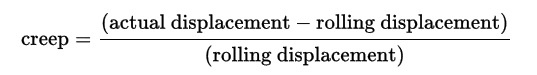
_
In analysing the dynamics of wheelsets and complete rail vehicles, the contact forces can be treated as linearly dependent on the creep (Kalker’s linear theory, valid for small creepage) or more advanced theories can be used from frictional contact mechanics. The forces which result in directional stability, propulsion and braking may all be traced to creep. It is present in a single wheelset and will accommodate the slight kinematic incompatibility introduced by coupling wheelsets together, without causing gross slippage, as was once feared. Provided the radius of turn is sufficiently great (as should be expected for express passenger services), two or three linked wheelsets should not present a problem. However, 10 drive wheels (5 main wheelsets) are usually associated with heavy freight locomotives.
__
Rolling resistance:
Rolling resistance, sometimes called rolling friction or rolling drag, is the force resisting the motion when a body (such as a ball, tire, or wheel) rolls on a surface. It is mainly caused by non-elastic effects; that is, not all the energy needed for deformation (or movement) of the wheel, roadbed, etc. is recovered when the pressure is removed. Two forms of this are hysteresis losses, and permanent (plastic) deformation of the object or the surface (e.g. soil). Another cause of rolling resistance lies in the slippage between the wheel and the surface, which dissipates energy. Note that only the last of these effects involves friction, therefore the name “rolling friction” is to an extent a misnomer. Rolling resistance is the term coined to account for the energy loss at the point of contact instead of rolling friction. In analogy with sliding friction, rolling resistance is often expressed as a coefficient times the normal force. This coefficient of rolling resistance is generally much smaller than the coefficient of sliding friction.
_
Any coasting wheeled vehicle will gradually slow down due to rolling resistance including that of the bearings, but a train car with steel wheels running on steel rails will roll farther than a bus of the same mass with rubber tires running on tarmac. Factors that contribute to rolling resistance are the (amount of) deformation of the wheels, the deformation of the roadbed surface, and movement below the surface. Additional contributing factors include wheel diameter, speed, load on wheel, surface adhesion, sliding, and relative micro-sliding between the surfaces of contact. The losses due to hysteresis also depend strongly on the material properties of the wheel or tire and the surface. For example, a rubber tire will have higher rolling resistance on a paved road than a steel railroad wheel on a steel rail. Also, sand on the ground will give more rolling resistance than concrete.
_
Empirical calculation of rolling resistance:
Rolling resistance of a train can be calculated by using empirical expression RR= A+BV+CV^2 Kg/ton, where ‘A’, ‘B’ & ‘C’ are constants, V is speed in Kmph and RR is rolling resistance of trains in Kg/ton. Constant ‘A’ mainly depends rolling resistance coefficient between wheel and rail and weight of train independent of speed. Constant ‘B’ mainly depends upon the sliding friction between the flange of the wheel & the inner face of the rail. Constant ‘C’ depends upon the cross-section area of train, space in-between coaches, equipment under the coaches, air resistance of the sides, draft and turbulence created by the train etc. Contribution of term “CV^2” is more visible with speed going more than 70 kmph. At high speed, aerodynamic drag becomes dominant.
_
Rolling resistance coefficient is very small of the order of 0.0001 as compared to sliding friction coefficient of 0.6 between two steel bodies. This is how Physics explains why rolling is easier than sliding.
Rolling resistance coefficient of rail road vs. road is as follows:
| Rolling Resistance Coefficients | |
| 0.001 – 0.002 | railroad steel wheels on steel rails |
| 0.001 | bicycle tire on wooden track |
| 0.002 | bicycle tire on concrete |
| 0.004 | bicycle tire on asphalt road |
| 0.008 | bicycle tire on rough paved road |
| 0.006 – 0.01 | truck tire on asphalt |
| 0.01 – 0.015 | car tires on concrete, new asphalt, cobbles small new |
| 0.02 | car tires on tar or asphalt |
| 0.02 | car tires on gravel – rolled new |
| 0.03 | car tires on cobbles – large worn |
| 0.04 – 0.08 | car tires on solid sand, gravel loose worn, soil medium hard |
| 0.2 – 0.4 | car tires on loose sand |
Thus Rolling Resistance Coefficient = 0.01 means that it would only take 0.01 pounds to tow a vehicle weighing one pound. For a 1000-pound vehicle, it would take10 pounds.
_
This also explains the main reasons for higher efficiency of rail transport as compared to Road. Trains can move a ton over 400 miles with one gallon of fuel because it’s very easy to just keep rolling on the tracks. Efficiency is slightly lost due to prevailing sliding friction between flange and inner face of rail which does not exists in road transport and higher tare weight per unit carrying capacity which is not so in road transport.
_
Ever wonder why trains have steel wheels, rather than tires like a car?
It’s to reduce rolling friction. When your car is driving on the freeway, something like 25 percent of the engine’s power is being used to push the tires down the road. Tires bend and deform a lot as they roll, which uses a lot of energy. The amount of energy used by the tires is proportional to the weight that is on them. Since a car is relatively light, this amount of energy is acceptable (you can buy low rolling-resistance tires for your car if you want to save a little gas). Since a train weighs thousands of times more than a car, the rolling resistance is a huge factor in determining how much force it takes to pull the train. The steel wheels on the train ride on a tiny contact patch — the contact area between each wheel and the track is about the size of a dime. By using steel wheels on a steel track, the amount of deformation is minimized, which reduces the rolling resistance. In fact, a train is about the most efficient way to move heavy goods.
The downside of using steel wheels is that they don’t have much traction. Traction when going around turns is not an issue because train wheels have flanges that keep them on the track. But traction when braking and accelerating is an issue. A locomotive can generate 64,000 pounds of thrust. But in order for it to use this thrust effectively, the eight wheels on the locomotive have to be able to apply this thrust to the track without slipping. The locomotive uses a neat trick to increase the traction. In front of each wheel is a nozzle that uses compressed air to spray sand, which is stored in two tanks on the locomotive. The sand dramatically increases the traction of the drive wheels. The train has an electronic traction-control system that automatically starts the sand sprayers when the wheels slip or when the engineer makes an emergency stop. The system can also reduce the power of any traction motor whose wheels are slipping.
_
Energy Efficiency of Rail vs. Truck vs. Air
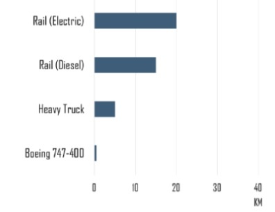
The figure above shows distance travelled for one ton of Cargo using 1 kWh of Energy. The transportation of freight relies on a variety of modes, each having its own level of energy performance. Rail is more efficient than trucks on roads and flying freight. Maritime shipping is more efficient than rail but the reach of maritime shipping is limited to port facilities.
_
Centrifugal force on curve:
The centrifugal (“to flee from the center”) force is the inertia that makes a body on a curved path want to continue outward in a straight line. It’s what keeps passengers in their seats on a looping roller coaster and throws unsecured kids off carousels. Centrifugal force is a function of the square of the train’s velocity divided by the radius of the curve; the smaller and tighter the curve, or the faster the train, the greater the centrifugal force. As it increases, more and more of the weight of the train is transferred to the wheels on the outermost edge of the track, something even the best-built trains have trouble coping with. That’s where the concepts of minimum curve radius and super-elevation, or banking, come in. Banked curves, in which the outer edge of the track is higher than the inner edge, balance the load on the train’s suspension. Since gravity pulls a train downward and centrifugal force pulls it outward, a track banked at just the right angle can spread the forces more evenly between a train’s inner and outer wheels, and help to keep it on the track.
_
Superelevation or canting of rails:
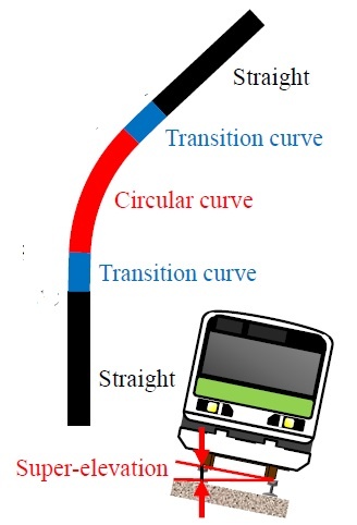
The outside rail on a curve is usually higher than the inside rail. The elevation of the outside rail relative to the inside rail is called superelevation.
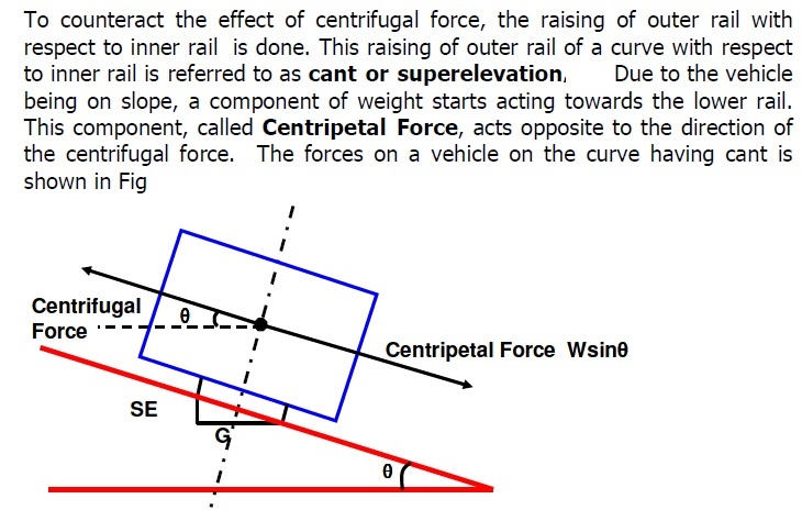
Assuming a suitably maintained track, maximum track speed through curves is limited by the “centrifugal force” which acts to overturn the train. To compensate for this force, the track is superelevated.
_
The speed at which the centrifugal force is perfectly offset by the tilt of the track is known as the balancing speed on curves:
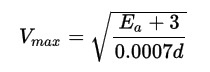
where Ea is the amount in inches that the outside rail is superelevated above the inside rail on a curve and d is the degree of curvature in degrees per 100 feet (30 m). Vmax is given in miles per hour i.e. balancing speed on curve.
_
Normally, passenger trains run above the balancing speed, and the difference between the balancing superelevation for the speed and curvature and the actual superelevation on the curve is known as unbalanced superelevation. Track superelevation is usually limited to 6 inches (150 mm), and is often lower on routes with slow heavy freight trains in order to reduce wear on the inner rail. The allowed unbalanced superelevation will cause trains to run with normal flange contact. The points of wheel-rail contact are influenced by the tire profile of the wheels. Allowance has to be made for the different speeds of trains. Slower trains will tend to make flange contact with the inner rail on curves, while faster trains will tend to ride outwards and make contact with the outer rail. Either contact causes wear and tear and may lead to derailment if speeds and superelevation are not within the permitted limits. Many high-speed lines do not permit the use of slower freight trains, particularly with heavier axle loads. In some cases, the wear or friction of flange contact on curves is reduced by the use of flange lubrication.
_
But canting the tracks isn’t a cure-all—a passenger train can tilt only so far before people fall out of their seats. So the minimum curve radius comes into play. Imagine that a curved portion of track is actually running along the outer edge of a large circle. How big must that circle be to insure that a train’s centrifugal force can be managed with only a reasonable amount of banking? It’s relatively easy to calculate these forces and the ways to counteract them, so it’s relatively easy to set a safe maximum speed for a certain kind of track. Tracks rated for fifty miles per hour need almost no banking and can have a curve radius of fifteen hundred feet, while a train traveling at a hundred and twenty miles per hour needs a track with significant banking, and a minimum curve radius of more than a mile and a half. However, badly maintained tracks, trains, or signals can sometimes contribute to a derailment.
_
The maximum speed a train can proceed around a turn is limited by the radius of turn, the position of the centre of mass of the units, the wheel gauge and whether the track is superelevated or canted. For a wheel gauge of 1.5 m, no canting, a centre of gravity height of 3 m and speed of 30 m/s (108 km/h), the radius of turn is 360 m. For a modern high speed train at 80 m/s, the toppling limit would be about 2.5 km. In practice, the minimum radius of turn is much greater than this, as contact between the wheel flanges and rail at high speed could cause significant damage to both. For very high speed, the minimum adhesion limit again appears appropriate, implying a radius of turn of about 13 km. In practice, curved lines used for high speed travel are superelevated or canted so that the turn limit is closer to 7 km.
_
Curve resistance (railroad):
In railroad engineering, curve resistance is a part of train resistance, namely the additional rolling resistance a train must overcome when travelling on a curved section of track. When a train goes around a curve, a centrifugal force push the train outward which increase the sliding friction resistance between outer wheel flange & the inner face of the outer rail. In addition to this, the outer wheel rotates faster than the inner wheel causing transverse slip thus adding to sliding friction. To overcome curve resistance, outer rail is gradually lifted above the level of the inner rail and difference in height between the inner and outer rail on a curve is called superelevation or cant. The necessary cant in a curve depends on the expected speed of the trains and the radius. If a train goes around a curve at speed such that the component of centrifugal force in the lateral direction is equal to the component of gravitational force in the opposite direction there is very little curve resistance. This speed is called balancing speed of the curve. If train speed is either higher or lower from curve balancing speed, the curve resistance increases due to the unbalance in forces which tends to pull the vehicle sideways.
_
Curve resistance is typically measured in per mile, with the correct physical unit being Newton per kilo-Newton or N/kN. Older texts still use the unit of kilogram-force per tonne or kgf/t, which mixes unit of force and a unit of mass. Sometimes also kg/t was used, which confused the resisting force with a mass. Curve resistance depends on various factors, the most important being the radius and the superelevation of a curve. Since curves are usually banked by superelevation, there exist some speed at which there will be no sideways force on the train and where therefore curve resistance is minimum. At higher or lower speeds, curve resistance may be a few (or several) times greater. Formulas typically used in railway engineering in general compute the resistance as inversely proportional to the radius of curvature (thus, they neglect the fact that the resistance is dependent on both speed and superelevation). The Russian experiments show that all these formulas are inaccurate. At balancing speed, they give a curve resistance a few times too high (or worse). However, these approximation formulas are still contained in practically all standard railway engineering textbooks.
__
Gradient resistance:
When the train travels upward, a component of its gravitational force works in a direction opposite to its motion and vice versa. Gradient Resistance is the force required to overcome train movement due to component of gravitational force acting on the train. If train is moving upward at a slope of θ, then the mass of the train (W) has two components; one perpendicular to the track (i.e. W X g X Cos θ) & the other along the track (i.e. W X g X Sin θ). The component along the track is known as gradient resistance.
Gradient Resistance = W X g X Sin θ Kilo Newton;
An up-grade produces a resistive force (+ve value) while a down-grade produces an accelerating force (-ve value). Value of gradient resistance is independent of train speed.
___
In a nutshell,
On straight & level track,
Train Resistance = Friction Resistance + Rolling Resistance + Air Resistance
On straight, curved and graded track,
Total Train Resistance = Train Resistance + Gradient Resistance + Curve Resistance
Total Train Resistance = Friction Resistance + Rolling Resistance + Air Resistance + Gradient Resistance + Curve Resistance
Note that some formulae of rolling resistance include air resistance in it.
_____
Tractive Effort:
The force at rail wheel contact exerted by a locomotive is called Tractive Effort. Tractive effort of the train is equivalent to the force developed by the traction units at the wheel rims for moving the train. In order to start a train and accelerate it to a given speed, the locomotive(s) must develop sufficient tractive force to overcome the train’s drag (resistance to motion), which is a combination of inertia, axle bearing friction, the friction of the wheels on the rails (which is substantially greater on curved track than on tangent track), and the force of gravity if on a grade. Once in motion, the train will develop additional drag as it accelerates due to aerodynamic forces, which increase with the square of the speed. Drag may also be produced at speed due to truck (bogie) hunting, which will increase the rolling friction between wheels and rails. If acceleration continues, the train will eventually attain a speed at which the available tractive force of the locomotive(s) will exactly offset the total drag, causing acceleration to cease. Balancing speed of train corresponds to the speed at which tractive effort of the train is equal to train resistance. At this speed, acceleration of train is supposed to zero. This top speed will be increased on a downgrade due to gravity assisting the motive power, and will be decreased on an upgrade due to gravity opposing the motive power. Once tractive effort and train resistance become equal, the speed cannot be further increased. The loco cannot continuously work on full power and hence potential tractive effort should be substantially higher than train resistance for better train operation. This also helps in attaining maximum speed quickly. Tractive effort can be theoretically calculated from a locomotive’s mechanical characteristics (e.g., steam pressure, weight, etc.), or by actual testing with drawbar strain sensors and a dynamometer car. Power at rail is a railway term for the available power for traction, that is, the power that is available to propel the train.
Power (kW) = Speed (m/s) X Tractive effort (kN)
____
Rotating mass:
Rotating mass of train is equivalent to the rotational Inertia of the train, transformed by gear ratio and wheel diameter respectively. The equivalent non-rotating mass of train may be defined as a function of its true static mass and its rotational inertia. It is based on the principle that the total energy stored in the object is a combination of its translational kinetic energy and its rotational kinetic energy and mentioned below:
Equivalent non-rotating mass of train = Static mass of train + Rotational inertia of train X (Gear ratio / wheel radius) 2
Above relationship is independent of the vehicle speed, so the consideration is valid at any velocity, and is independent of vehicle power. Generally, rotating mass of a metro train is considered 6 to 8 % of the tare mass of train.
_______
Hunting oscillation on railway wheel-sets:
Hunting oscillation is a self-oscillation, usually unwanted, about an equilibrium. The expression came into use in the 19th century and describes how a system “hunts” for equilibrium. The expression is used to describe phenomena in such diverse fields as electronics, aviation, biology, and railway engineering. A classical hunting oscillation is a swaying motion of a railway vehicle (often called truck hunting) caused by the coning action on which the directional stability of an adhesion railway depends. It arises from the interaction of adhesion forces and inertial forces. At low speed, adhesion dominates but, as the speed increases, the adhesion forces and inertial forces become comparable in magnitude and the oscillation begins at a critical speed. Above this speed, the motion can be violent, damaging track and wheels and potentially causing derailment. Shortly after the onset of hunting, gross slippage occurs and the wheel flanges impact on the rails, potentially causing damage to both.
_
Hunting oscillation front view:
_
_
Hunting oscillation top view:
_
The problem was first noticed towards the end of the 19th century, when train speeds became high enough to encounter it. This behaviour limited trains to operate at speeds of about 225 km/h (140 mph) or less and led to a number of research projects in the 1960s using hover trains and maglev systems to avoid it and reach higher speeds. But after empirical studies by the British Rail Research Division in the 1960s, remedial measures, particularly in the design of suspension systems, have been introduced permitting speeds exceeding 290 km/h (180 mph). As a result of this research, most high-speed trains today still use steel wheels, rather than more expensive technologies.
______
______
How train stays and runs on rail:
Figure below shows the shape and location of wheels and rails on straight track. This diagram is exaggerated to show the principal of the wheel/rail interface on straight track. Note that the flanges do not normally touch the rails.
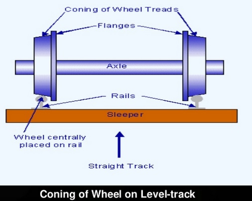
_
Railway wheels sit on the rails without guidance except for the shape of the tyre in relation to the rail head. Contrary to popular belief, the flanges should not touch the rails. Flanges are only a last resort to prevent the wheels becoming derailed – they’re a safety feature. The wheel tyre is coned and the rail head slightly curved as shown in the figure above. The rails are also set at an inward angle. Ideally, the wheel profile should be determined by agreement between the railway infrastructure owner and the rolling stock owner. Of course, it varies from place to place but it is rarely a simple angle. It’s usually a carefully calculated compound form. With respect to the rail angle, in the UK for example, it is set at 1 in 20 (1/20 or 0.05). In the US and France it’s usually at 1/40. Light rail systems operating over roadways will have special profiles.
_
It may be thought that the wheels are kept on the tracks by the flanges. However, close examination of a typical railway wheel reveals that the tread is burnished but the flange is not – the flanges rarely make contact with the rail and, when they do, most of the contact is sliding. The rubbing of a flange on the track dissipates large amounts of energy, mainly as heat but also including noise and, if sustained, would lead to excessive wheel wear. Centring is actually accomplished through shaping of the wheel. The tread of the wheel is slightly tapered, coning of wheels. When the train is in the centre of the track, the region of the wheels in contact with the rail traces out a circle which has the same diameter for both wheels. The velocities of the two wheels are equal, so the train moves in a straight line. If, however, the wheelset is displaced to one side, the diameters of the regions of contact, and hence the tangential velocities of the wheels at the running surfaces are different and the wheelset tends to steer back towards the centre. Also, when the train encounters an unbanked turn, the wheelset displaces laterally slightly, so that the outer wheel tread speeds up linearly, and the inner wheel tread slows down, causing the train to turn the corner. Some railway systems employ a flat wheel and track profile, relying on cant alone to reduce or eliminate flange contact.
_
Understanding how the train stays on the track, it becomes evident why Victorian locomotive engineers were averse to coupling wheelsets. This simple coning action is possible only with wheelsets where each can have some free motion about its vertical axis. If wheelsets are rigidly coupled together, this motion is restricted, so that coupling the wheels would be expected to introduce sliding, resulting in increased rolling losses. This problem was alleviated to a great extent by ensuring the diameter of all coupled wheels was very closely matched.
_
With perfect rolling contact between the wheel and rail, this coning behaviour manifests itself as a swaying of the train from side to side. In practice, the swaying is damped out below a critical speed, but is amplified by the forward motion of the train above the critical speed. This lateral swaying is known as hunting oscillation [vide supra]. The limitation on maximum speed was imposed not by raw power but by encountering an instability in the motion. The kinematic description of the motion of tapered treads on the two rails is insufficient to describe hunting well enough to predict the critical speed. It is necessary to deal with the forces involved. There are two phenomena which must be taken into account. The first is the inertia of the wheelsets and vehicle bodies, giving rise to forces proportional to acceleration; the second is the distortion of the wheel and track at the point of contact, giving rise to elastic forces. The kinematic approximation corresponds to the case which is dominated by contact forces.
_
Trains stay on the tracks because of its weight and the coning wheels, not the lip or flange on the inside of the wheel:
More specifically, because
- the outside diameter of the wheel is smaller than the inside (+wheels are inside the track)
- the tracks are always the same distance apart
- the axle is locked
When you put it all together, if the train was to move to one side, that side would then have a larger diameter wheel on the track, so that side of the train starts travelling faster than the other side, steering it back towards the middle.
______
______
How train turns on curved track:
Steering is not required in a locomotive because navigation is achieved by the rails/tracks. The train’s wheels are fixed and it is only the rails that give direction to the moving train. The provision of differential is there in every 3+ wheeler land vehicles, from a cycle rickshaw to cars to trucks to buses. While negotiating the curve, the distance travelled by the outer wheel pair is more than the distance travelled by the inner wheel pair. In order to achieve this, the motion of the two wheels connected together on one axle, should be independent of each other. This is achieved in case of cars by incorporating a differential gear. The power of the car engine is transmitted to the two wheels of the driven axle through a differential gear. However, coming back to the trains, since both the wheels are pressed fitted to the axle; the motion is NOT independent to each other. The rotational velocity of both the wheels remains the same. Hence, now the question arises that, how the train negotiates a curve, when the rotational speed of both the wheels are same. How will the two wheels fitted to an axle, will travel two different distances when they cannot travel at two different speeds? In trains, the wheel is profiled such that it itself performs the function of the differential.
_
If we look closely, the profile of the wheel, we can notice that it is slightly tapered from flanged side to the non-flanged side i.e. coning of wheel. Hence, the diameter of the wheel towards the flanged side will be more than the diameter of the wheel towards the non-flanged side. When the train is negotiating a curve, the body of the train tends to align itself such that when, a train is negotiating a right turn, the point of contact between the wheel and rail tend to get shifted towards the right side as centrifugal force tries to shift train and its wheel-set laterally towards left side. Hence, for the left wheel, the point of contact between the wheel and rail will be nearer to the flanged side and for the right wheel, the point of contact between the wheel and rail will be towards non-flanged side. See figure below. Hence, for the left wheel, the cross-section of the wheel with higher diameter will be in contact with the rail, and for the right wheel, the cross-section of the wheel with lower diameter will be in contact with the rail. Now, the rotational velocity of both the wheels is same, however, since during curve, different diameter cross-section of each wheel will be actually be running on rails, the distance travelled by outward wheel while negotiating the curve (left wheel in case of right turn) will be more than the distance travelled by the inner wheel (right wheel in case of right turn). Hence, in order to fulfil all the requirements of the wheels of the train, the flange always have to be inwards. A wheel with an outward flange will never be able to fulfil the above requirements. Role of flange of wheel when train moves on curved track is to prevent derailment but train motion on curved track occurs due to conicity of wheels and not flanges. Note that coning helps, not only in covering turns, but also to maintain the train in center of tracks during normal running of train on straight track.
_
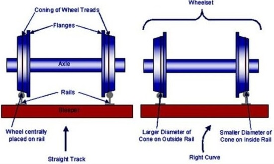
_
The flange of the outer wheel will touch the curved rail only when the movement of the train round is not in exact symmetry with the geometry of the track. This can occur due to incorrect speed or poor mechanical condition of the track or train. It often causes a squealing noise. It naturally causes wear. Many operators use flange or rail greasing to ease the passage of wheels on curves. Devices can be mounted on the track or the train. It is important to ensure that the amount of lubricant applied is exactly right. Too much will cause the tyre to become contaminated and will lead to skidding and flatted wheels. There will always be some slippage between the wheel and rail on curves but this will be minimised if the track and wheel are both constructed and maintained to the correct standards.
_
Wheels shape experiment:
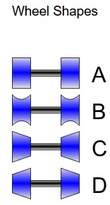
There was a curved track and four sets of wheels. Each set of wheels had a different cross-section (as shown above). To no great surprise, when one rolled the flat wheels (A) down the track, they rolled perfectly straight and fell off at the first curve. The double-flanged wheels (B) also ran perfectly straight (which is surprising until one thinks about it). The outside-flanged wheels (C) actively veered off to one side or the other. The inside-flanged wheels (D) were self-centering and wobbled their way to the end of the track without derailing. It is a fantastic demonstration of mechanical self-centering (as wheel D drifts left, the diameter of the left wheel increases which makes it travel further, forcing the axle to swerve right).
_

In above video from Numberphile, a YouTube channel dedicated to mathematics and science, Tadashi Tokieda, Director of Studies in Mathematics at Trinity Hall, Cambridge, explains how two sets of plastic cups, taped together on opposite ends, demonstrate the difference between stability and instability. When the tops of the cups are taped together, the cups are able to roll all the way down a set of parallel tracks without falling off. But when the cups are taped together at the bottom, they will always veer to the left or right and eventually roll right off. The results have nothing to do with how perfectly the cups are centered at the top of the track before they roll. As they veer to the right or left, the diameter of the cups on either side changes, resulting in what is essentially a pair of connected wheels that are each a different size. Because a larger wheel rolls farther than a smaller one in the same amount of time, the taped cups never roll perfectly straight. However, the version where the cups are taped together at the top is able to continuously self-correct itself as it rolls, allowing it to make its way all the way down the tracks without falling off. As Tokieda explains, it’s that unique self-steering behavior that allows a train to stay on the tracks as it goes around corners. A track’s outer rail is actually physically longer than the inner one, which would require two perfectly cylindrical wheels to turn at two different speeds on either side. To solve that problem, engineers designed train wheels with an angle so that as the train navigates a corner, the wheels can shift from side-to-side, essentially changing their sizes in real-time. The wheels on one side end up with a larger diameter, covering more distance to handle the longer outer track, while the wheels on the other side get smaller to handle the shorter distance on the inner track. It all happens automatically thanks to centrifugal forces pushing the train outwards as it rounds a corner, which means no one has to do anything to ensure the train doesn’t derail.
_____
______
How train change track while running:
There are switches in the tracks, with moving parts that lead the train either to the left track or the right track. The switches are usually remotely controlled from a traffic operations center. For drivers, there are signals that indicate that the switches are locked in the correct position. Trains switch tracks using a simple conventional mechanism known as “Switch and Crossover”. To make a train change its track, a special mechanical arrangement is made. This arrangement is known as a railroad switch and it consist of pair of rails, known as switching rails or points, that are linked to one another. As the name suggests, the switching rails can direct or guide the train, either on straight path or on the diverging path which is established by a curved rail line. When trains “change tracks” it is the track that changes first. The train just follows the changed track. The track has to align properly or the wheels won’t continue along the rail. If you look closely you will see a “flange” on the inside of the wheel. This rides along the inside of the rail. When trains switch from track to track the flange is just following the inside path of the way the rail is aligned. A vehicle with outside flanges cannot negotiate the points and crossings designed for wheels with inside flanges. The flanges of a railroad wheel are on the inside because it is easier to make a switch that operates on the inside flanges than on outside flanges. Switches could be made to operate with outside flanges, but, they would be much more complicated and expensive. The railroad switch can only be in one of the two positions at a time. If it is locked the train will change the track. If it is open, it will go straight-through. It is very important that the switch is set up carefully. Most train derailments take place at the point when it goes from one track to another track. A loose set up is a guarantee of making train jump off the track, a disaster. However, railway authorities around the world has expertise the art of train track changing. Most times the process is so smooth, that one even doesn’t notice it. However an experienced traveller can make out with the sound of the train, that indeed the track is changed.
_
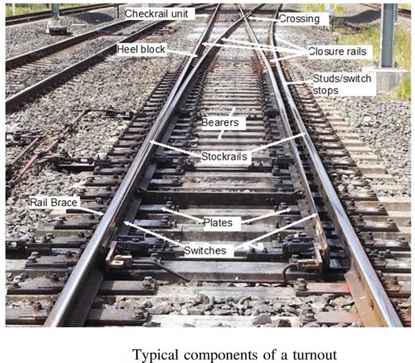
A railroad switch, turnout or [set of] points is a mechanical installation enabling railway trains to be guided from one track to another, such as at a railway junction or where a spur or siding branches off. The switch consists of the pair of linked tapering rails, known as points (switch rails or point blades), lying between the diverging outer rails (the stock rails). These points can be moved laterally into one of two positions to direct a train coming from the point blades toward the straight path or the diverging path. A switch generally has a straight “through” track (such as the main-line) and a diverging route. The handedness of the installation is described by the side that the diverging track leaves. Right-hand switches have a diverging path to the right of the straight track, when coming from the point blades, and a left-handed switch has the diverging track leaving to the opposite side. In many cases, such as rail yards, many switches can be found in a short section of track, sometimes with switches going both to the right and left (although it is better to keep these separated as much as feasible). Sometimes a switch merely divides one track into two; at others, it serves as a connection between two or more parallel tracks, allowing a train to switch between them. In many cases, where a switch is supplied to leave a track, a second is supplied to allow the train to reenter the track some distance down the line; this allows the track to serve as a siding, allowing a train to get off the track to allow traffic to pass (this siding can either be a dedicated short length of track, or formed from a section of a second, continuous, parallel line), and also allows trains coming from either direction to switch between lines. A straight track is not always present; for example, both tracks may curve, one to the left and one to the right (such as for a wye switch), or both tracks may curve, with differing radii, while still in the same direction.
_
The operation of a railroad switch:
In this animation, the red track is the one travelled during a facing-point movement. The switch mechanism, shown in black, may be operated remotely using an electric motor or hand-operated lever or from a nearby ground frame. When the wheels reach the switch, the wheels are guided along the route determined by which of the two points is connected to the track facing the switch. In the illustration, if the left point is connected, the left wheel will be guided along the rail of that point, and the train will diverge to the right. If the right point is connected, the right wheel’s flange will be guided along the rail of that point, and the train will continue along the straight track. Only one of the points may be connected to the facing track at any time; the two points are mechanically locked together to ensure that this is always the case. A mechanism is provided to move the points from one position to the other (change the points). Historically, this would require a lever to be moved by a human operator, and some switches are still controlled this way. However, most are now operated by a remotely controlled electric motor or by pneumatic or hydraulic actuation, called a point machine. This both allows for remote control and for stiffer, strong switches that would be too difficult to move by hand, yet allow for higher speeds.
_
If a switch becomes worn or the operating rods become damaged, it is possible for the flange to split the switch, and go through the switch in the direction other than what was expected. This happens when the flange strikes a small gap between the fixed rail and the set switch point (whichever is touching the main line); this forces the switch open, and the train is diverted down the incorrect track. This can either happen to the locomotive, in which case the whole train can be directed onto the wrong track, with potentially dangerous results, or it can occur at any point through the train, when a random truck is directed down a different track from the rest of the train; if this happens on the front truck of a car, the usual result is derailment, as the trailing truck of the preceding car attempts to go one way, while the leading truck of the following car tries to go another. If it happens to the trailing truck of a car, the front truck will follow one track, while the trailing truck follows a parallel line; this causes the whole car to “crab”, or move sideways down the track (derailment often results eventually, due to the lateral forces applied when the train tries to brake or accelerate). This can have disastrous results if there is any obstacle between the lines, as the car will be propelled into it sideways. It would be possible, at least theoretically, to build a rail switch with linkages strong enough that they would not bend under the force of the flanges of train wheels pushing one of the points away from the adjacent fixed rail, so that the points would never move during a trailing-point movement, at least as long as the speed of the train was not excessive. Then, in a trailing-point movement along the route that the points were not set to, the switch would not be damaged, but instead the train would derail. Obviously, it is preferable for the switch to give way and be damaged than for the train to derail, causing damage to it and possible injury or loss of life to people aboard the train or nearby.
_
High-speed operation at switches:
Generally, switches are designed to be safely traversed at low speed. However, it is possible to modify the simpler types of switch to allow trains to pass at high speed. More complicated switch systems, such as double slips, are restricted to low-speed operation. On European High Speed Lines, it is not uncommon to find switches where a speed of 200 km/h (124.3 mph) or more is allowed. Switches were passed over at a speed of 560 km/h (348.0 mph) during the French world speed run of April 2007. The conventional way to increase turnout speeds is to lengthen the turnout and use a shallower frog angle. Higher speeds are possible without lengthening the turnout by using uniformly curved rail and a very low entry angle; however, wider track centers may be needed.
_
Switch Operation in cold conditions:
In cold conditions, snow and ice can prevent the correct operation of switches. In the past, people were employed by railway companies to keep the switches clear by sweeping the snow away, and this is still used in some countries, especially on minor lines. Some were provided with gas torches for melting ice. More recently, switches have had heaters installed in the vicinity of the points so that the temperature of the rails in these areas can be kept above freezing. The heaters may be powered by gas or electricity. In cases where gas or electric heaters cannot be used due to logistical or economical constraints, anti-icing chemicals can be applied to create a barrier between the metal surfaces of the switch and ice. Heating alone may not be enough to keep switches functioning in snowy conditions. If the snow is particularly sticky, as it may be in temperatures just below freezing, chunks of ice may accumulate on trains. When the train passes over some switches, the shocks, possibly in combination with slight heating caused by braking or a city microclimate, may cause the chunks of ice to fall off, jamming the switches. The heaters need time to melt the ice, so if service frequency is high, there may not be enough time to melt the ice before the next train arrives, disrupting services. Possible solutions are installing higher capacity heaters, reducing the frequency of the timetable or applying anti-icing chemicals like ethylene glycol to the trains.
______
______
Train Sound:
Why is sound produced when the train moves over the track?
Why is this sound not continuous but in a particular rhythm?
The rails (permanent way) are of standard length, and wheels of the coaches (under carriage) are fitted at standard places underneath the coaches. When the coaches are on the move, the wheels transit from one rail to the next one and because of a small gap at fishplates between the rails, the sound is produced. In view of the standard length of the rails and the placement of the wheels under the coaches there is the rhythm. When the train is running at high speed the interval between the rhythms is less while the interval is long when the train is running at slow speed. In continuous welded rail, rail is ¼ mile long, so it provides a quiet, smooth ride in comparison to jointed track. Indian Railway is experimenting with the rails that have their ends cut at 45 degrees angles. In this when the coach is on the move from one rail to the other (the next one) there is no sound since the wheel is already on the next rail, before leaving the earlier one. In this the fish plates have to be used instead of welding the joints.
_
Rail squeal:
Rail squeal is a screeching train-track friction sound, commonly occurring on sharp curves. The noise can be annoying to nearby residents. Squeal is presumably caused by the lateral sticking and slipping of the wheels across the rail head. The flange of the outer wheel may touch the outer rail on curve generating squeal. The vibrations in the wheel increases until a stable amplitude is reached. Lubricating the rails has limited success. Speed reduction also appears to reduce noise levels. The mechanism that causes the squealing also is the cause of wear and tear that is happening to both rails and wheels.
______
______
Railway accidents:
Train accidents cause damage to infrastructure and rolling stock as well as service disruptions, and may cause casualties and harm the environment. Accordingly, improving train operating safety has long been a high priority of the rail industry and the government. Train accidents occur as a result of many different causes; however, some are much more prevalent than others. Furthermore, the frequency and severity of accidents also varies widely, depending on the particular accident cause. Efficient allocation of resources to prevent accidents in the most cost-effective manner possible requires understanding which factors account for the greatest risk, and under which circumstances. Assessment of the benefits and costs of strategies to mitigate each accident cause can then be evaluated and resources allocated so that the greatest safety improvement can be achieved for the level of investment available.
_
There are a variety of different reasons that railroad accidents occur, and some of these include:
- Train conductor negligence
- Train derailment
- Improper maintenance of the train tracks
- Faulty equipment
- Collision with another train
- Collision with a car, bus or truck trying to cross train tracks
- Collapsed bridges
- Faulty train crossings
_
Accident by track type:
Four types of tracks are recorded in the FRA (Federal Railroad Administration) database—main, siding, yard, and industry tracks. These track types are used for different operational functions and consequently have different associated accident types, causes, and consequences. Train accidents are categorized into derailment, collision, highway–rail grade crossing accident, and several other less frequent types. When there is more than one type of accident, the type of accident that occurred first would be designated for all reports related to it. For example, a derailment caused by a collision would be classified as a “collision.” Highway–rail grade crossing accidents in the FRA database include only those that occur at the highway–rail interface and involve at least one highway user.
_
Railway accidents in the US:
In the United States alone, there are approximately 600 railroads, hundreds of thousands of miles of tracks, and over 209,000 railroad crossings. Although railroads are not used as often as they were in centuries past, they still remain quite active. Unfortunately, serious and fatal accidents involving trains also remain active. According to the National Transportation Safety Bureau, nearly every 2 hours, a person or vehicle is hit by a train in the U.S. Rail accidents and/or incidents include the following scenarios:
- Derailment
- Train-train collisions
- Train-car collisions
- Train-person collisions
- Damage to property
Each year nearly 1,000 people are killed in train related accidents. Additionally, United States train and railroad accident statistics estimate that almost every two weeks a train derailment leads to a chemical spill. Some of these spills are so serious that they require the evacuation of local residents. Aside from being extremely tragic and devastating, train and railroad accidents can be very complex and difficult for the victims.
_
Rail accident fatalities in the EU:
In 2015, 1808 significant railway accidents have been reported in the EU-28, in which a total of 963 persons were killed; another 684 persons have been seriously injured. At the level of the EU (however without Croatia and Luxembourg for time series consistency), the number of fatalities has gradually decreased, from 1517 in 2007 to 948 in 2015 (-37 %). Suicides occurring on the railways are reported separately, and with 2762 reported cases in 2015, these outnumber by a considerable margin the victims accounted for in the railway safety statistics. To measure the relative safety of rail transport, the number of accidents and the related number of victims have to be linked to traffic performance (expressed in passenger-kilometres and tonne-kilometres). As the number of passengers killed in rail accidents is very low each year, it is important to keep in mind that one single accident – or even one single victim – can have a big impact when comparing countries or the annual number of passengers killed per billion passenger-kilometres. Bulgaria registered the highest ratio in 2015 (1.29 passengers killed per billion passenger-kilometres) ahead of Czech Republic (0.74): all the other reporting countries recorded a ratio below 0.6 in 2015. For a large majority of countries, this indicator increased or remained stable between 2014 and 2015. Only Spain, Poland, Switzerland and Turkey showed this ratio decrease in 2015 compared to 2014.
_
Comparative Rail Safety:
China: one death per 55.3 billion passenger-km
Japan: one death per 51.4 billion passenger-km
EU: one death per 12.8 billion passenger-km
South Korea: one death per 6.7 billion passenger-km
India: one death per 6.6 billion passenger-km.
US: one death per 3.4 billion passenger-km.
China not only has the safest passenger trains, but also by far the busiest tracks.
_
Analysis of train derailment causes in Victoria, Australia, between 2007 and 2013:
Between January 2007 and December 2013, Transport Safety Victoria recorded 122 mainline derailments. Passenger trains accounted for 19% of mainline derailments whereas freight trains accounted for 52%. Track maintenance vehicles and locomotives running without wagons or coaches attached accounted for the remaining 29% of derailments. Infrastructure defects were determined to be a causal factor in 56% of derailments, operations related factors in 40% of derailments, and rolling stock in 12% of derailments. No cause could be determined in 10% of derailments, whereas some derailment incidents identified more than one cause.
Rail safety in Australia:
The responsibility for rail safety in Australia is shared by government and industry. The present database contains frequency counts of the following safety-critical event types:
- Derailment
- Collision
- Level Crossing Occurrence
- Signal Passed at Danger (SPAD)
- Loading Irregularity
- Track and Civil Infrastructure Irregularity
As the data is collected and published on a jurisdictional basis, frequency counts for each of the above occurrences should be normalised according to the size of the industry. The normalising data provided is
- Train kilometres
- Freight-train kilometres
- Passenger-train kilometres
- Total track kilometres
In addition, frequency counts are provided for
- Deaths
- Serious Injuries
______
Classification of railway accidents, both in terms of cause and effect, is a valuable aid in studying rail accidents to help to prevent similar ones occurring in the future. Systematic investigation for over 150 years has led to the railways’ excellent safety record (compared, for example, with road transport). Ludwig von Stockert (1913) proposed a classification of accidents by their effects (consequences); e.g. head-on collisions, rear-end collisions, derailments. Schneider and Mase (1971) proposed an additional classification by causes; e.g. driver’s errors, signalmen’s errors, mechanical faults. Similar categorisations had been made by implication in previous books e.g. Rolt (1956), but Stockert’s and Schneider/Mase’s are more systematic and complete. With minor changes, they represent best knowledge.
______
Classification of rail accidents by effects:
Collisions:
- Head-on collision
- Rear collision
- Slanting collision
- Collisions with buffer stops
- Collisions with obstructions of the track (may also cause derailment)
Derailments:
- Plain track
- Curves
- Junctions
Other:
- Fires, explosions and release of hazardous chemicals (including sabotage/terrorism)
- People falling from trains, collisions with people on tracks
_____
Classification of rail accidents by causes:
- Trespassing railway tracks
- Drivers’ errors
- Passing signals at danger
- Excessive speed
- Mishandling of the engine (e.g. boiler explosions)
- Failure to check brakes and safety systems as well as sand reserve
- Failure to stop at required positions, e.g. level crossings with defective equipment or shunting movements that lead to occupied tracks.
- Signalmen’s errors
- Allowing two trains into same occupied block section
- Incorrect operation of signals, points or token equipment
- (Mechanical) failure of rolling stock
- Poor design
- Poor maintenance
- Undetected damage
- Overloading or freight that is not adequately secured.
- Fire starting from combustion motors, electric cables or equipment, leaking fuel or cooling oil
- Civil engineering failure
- Track (permanent way) faults
- Bridge and tunnel collapses
- Poor track or junction layout
- Acts of other people
- Other railway personnel (shunters, porters, maintenance personnel, etc.)
- Non-railway personnel
- Accidental e.g. Accidental track obstruction e.g. with road vehicles or by working construction vehicles
- Deliberate (vandalism, terrorism, suicide, extortion, sabotage) e.g. Deliberate track obstruction with road vehicles or (heavy) objects, Intentional damage to infrastructure like tracks, points or signals, Level crossing misuse and Trespassing.
- Natural causes
- Track obstruction or damage by landslides, avalanches, floods, trees
- Fog or snow that obscure signals or the current position of the train
- Wet leaves (or their remains) making the tracks slippery.
- Contributory factors
- Strength of rolling stock
- Fire hazards or dangerous goods in the train, in involved road vehicles or the vicinity
- Effectiveness of brakes
- Inadequate rules
______
_______
Derailment and its causes:
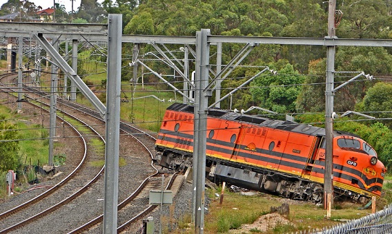
_
Train derailments are one of the major undesirable events to be considered in railway safety system and potentially pose serious hazards to human health and safety. A derailment is when a railroad car or locomotive is no longer properly supported by the rails under it. Not all railroad accidents cause derailments. A derailment is one type of railroad incident. Train derailments are like flat tires on cars – they do happen, and depending on how fast you are going and where you are, it can be a minor delay, or a major problem. Train tracks are sort of like roads in that they are designed, classified, and maintained for different speeds. Some train tracks are maintained to a very high level, to handle many trains a day, and very high speeds. Other tracks are maintained for an occasional train moving at 10mph or so. There are 9 classes of railroad track in the US, from 10mph up to 220mph. Railroads with the heaviest traffic are inspected daily to make sure that everything is in good shape. A railroad track inspector will slowly drive down the section of track with a special truck, and stop and inspect anything that doesn’t look or feel right. Most of the derailments that happen are low-speed derailments, and not something the general public needs to worry about. A low-speed derailment is not a big deal. Just because a train car derails doesn’t mean it will tip over, catch fire, or explode. The rail is only about 6 inches high – the car will bounce along the ballast and wooden ties until the train comes to a stop. To put the car back on the rails, you need to raise it up about 6 inches or so – often it is done just by making a ramp out of oak timbers (wood), and just pulling the car back on to the rails. Often there is very little to no damage to the railroad car. These types of derailments often happen in railroad yards with lots of switches, where trains cross from one track to another. A derailment does not mean someone failed to do their job, was negligent, or not paying attention – like a flat tire, sometimes they just happen. Occasionally trains do derail at high speeds, with dangerous cargo that could catch fire and explode, but that doesn’t happen very often – maybe once a year or so, and those incidents are usually on the national news.
_
Derailments are the most common type of train accident, and preventing them has long been a focus of the rail industry and the government. Most previous studies have focused on main-line derailments, with less research published on yard and siding derailments. The derailment-cause distribution on main lines differs from distributions on yard or siding tracks, in part because of the different nature of operations in these two settings. Understanding the top causes affecting train derailment occurrence and number of cars derailed on different tracks provides additional insight into the development, evaluation, prioritization, and implementation of accident prevention strategies given a specific set of operating conditions.
_
Weighing in the thousands of tons, trains are behemoths that, once moving, take great energy and space to slow down or come to a stop. A derailment occurs when a vehicle such as a train runs off its rails. This does not necessarily mean that it leaves its track. Although many derailments are minor, all result in temporary disruption of the proper operation of the railway system, and they are potentially seriously hazardous to human health and safety. Usually, the derailment of a train can be caused by a collision with another object, an operational error, the mechanical failure of tracks, such as broken rails, or the mechanical failure of the wheels. In emergency situations, deliberate derailment with derails or catch points is sometimes used to prevent a more serious accident. During the 19th century derailments were commonplace, but progressively improved safety measures have resulted in a stable lower level of such incidents. In the US, derailments have dropped dramatically since 1980 from over 3,000 annually (1980) to 1,000 or so in 1986, to about 500 in 2010.
_
Derailment is where one or more rolling stock wheels leave the rail or track during railway operations.
Running Line Derailment is any derailment that affects the safe operation of a running line.
Includes:
- The derailment of a train which has been authorised to depart and has commenced its journey to operate on a running line.
- Track machine derailments if they are traveling on the line as a running train.
- Shunting derailments occurring on running lines within station limits.
- A derailment in a yard or siding that results in the running line being obstructed or interferes with the safe operation of a running line.
- A derailment on a portion of track closed for maintenance or other purposes that results in obstruction of a non–closed running line or interferes with the safe operation of a non–closed running line.
Excludes:
- A derailment on a portion of track closed for maintenance or other purposes where there is no possibility that the safe operation of any non-closed running line is affected.
- Derailments of rolling stock on loop lines, equipped with roll out protection (e.g. derailers) to protect the main line, which are temporarily being used for the stabling of rolling stock.
- Derailments on balloon loops during the loading and unloading process not involving a train that has been authorised to depart and has commenced its journey to operate on a running line.
_
Derailment is caused by three main factors. There can be mechanical reasons, like broken rails, or lack of maintenance of tracks. Derailment caused by mechanical reasons has reduced over the years. Derailment can also be caused due to functional reasons, a result of high speed, poor signalling or human error. The third and most important reason for derailment is geotechnical. Derailment is caused by misalignment of rails and sleepers because of problems with the foundation on which it rests.
_
Derailment statistics:
In the recent past, several accidents due to derailing of trains have been reported in various parts of India. In the 6-year period between 2009-10 and 2014-15, there were a total of 803 accidents in Indian Railways killing 620 people and injuring 1855 people. 47% of these accidents were due to derailment of trains. According to Indian official figures, of a total of 586 rail accidents in the last five years, nearly 53 per cent were due to derailments. The worst accident was the Nov 20, 2016 derailment of the Indore-Patna Express near Kanpur which resulted in 150 deaths and over 150 injuries. Openly accessible data shows that over 40 per cent of all rail accidents in India have been cases of the train going off the rails. A 2014 study in the US found that derailments are most common class of railway accidents i.e.70% of all accidents.
_
According to a report by the Scientific American, between 2001 and 2010, of the 58,299 train accidents that occurred, 54,889 – or 94 per cent – were train derailments. Almost anything can derail a train under the right circumstances including a defect in the track itself, however almost nothing will. Broken rails and welds are the most common cause of train derailments. They account for more than 15 percent of derailments, according to data from the Federal Railroad Administration. Broken rails and welds were more than twice as likely to have been the cause of train derailments than the second and third leading causes—track geometry and bearing failure. Track geometry, which includes such things as train alignment, gauge and elevation, was responsible for 7.3 percent of derailments and bearing failure was responsible for 5.9 percent.
_
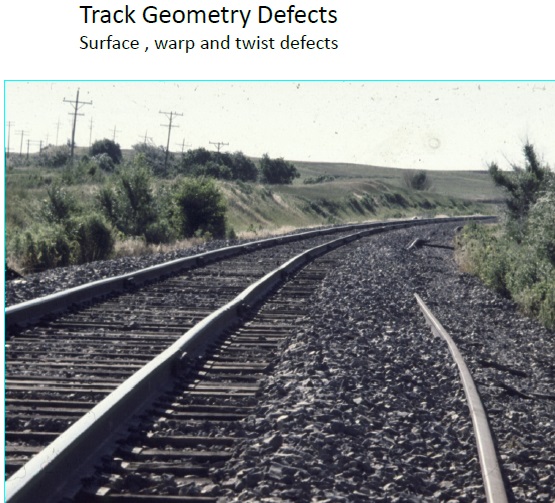
Track geometry defects appear in about 50% of accidents where more than one cause is present, with track twist the most significant appearing in about 30%. Wheel profile defects appear in about 20% of accidents where more than one cause is present. Wagon wrongly loaded appears in about 10% of accidents where more than one cause is present. Train mishandling appears in 10% of accidents where more than one cause is present.
_
About 70% of low speed derailments occur in or around stations.
About 25% of low speed derailments are immediately severe (potential for loss of containment).
About 30% of high speed derailments occur in or around stations.
About 50% of high speed derailments are immediately severe.
_
Figure below shows causes of main-track derailment in the US:
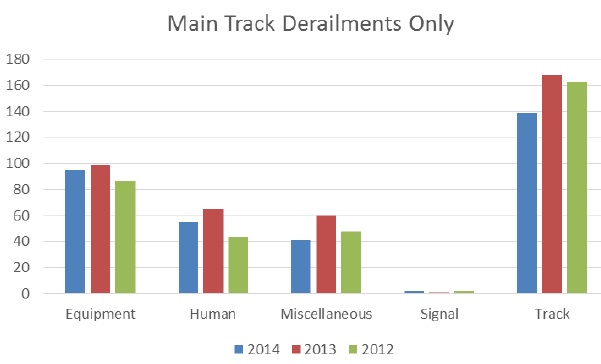
_
_
Figure below shows causes of track failure resulting in derailments in the US:
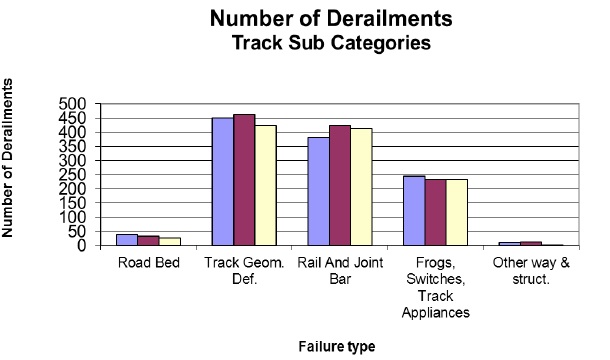
______
______
Derailments result from one or more of a number of distinct causes; these may be classified as:
- the primary mechanical failure of a track component (for example broken rails, gauge spread due to sleeper (tie) failure)
- the primary mechanical failure of a component of the running gear of a vehicle (for example axlebox failure, wheel breakage)
- a fault in the geometry of the track components or the running gear that results in a quasi-static failure in running (for example rail climbing due to excessive wear of wheels or rails, earthworks slip)
- a dynamic effect of the track-vehicle interaction (for example extreme hunting, vertical bounce, track shift under a train, excessive speed)
- improper operation of points, or improper observance of signals protecting them (signal errors)
- as a secondary event following collision with other trains, road vehicles, or other obstructions (level crossing collisions, obstructions on the line)
- train handling (snatches due to sudden traction or braking forces, referred to as slack action in North America).
_______
A study analysis produced this ranking of derailment causes for Europe:
1 Axle ruptures
2 Excessive track width
3 Wheel failure
4 Skew loading
5 Excessive track twist
6 Track height or cant failure
7 Rail failures
8 Spring and suspension failure
______
The U.S. Federal Railroad Administration categorises derailments differently, for the use of professionals in the industry:
- Rail, joint bar and anchoring
- Track geometry defect
- General switching rules
- Wheels
- Axles and journal bearings
- Switches
- Frogs, switches and track appliances
- Bogie (truck) components
- Train handling / train make-up
- Highway rail grading
_______
Derailment causes according to 103 accidents study:
- Infrastructure causes (including combinational causes where infrastructure is a contributing cause) accounting for 35% – 45% of derailments within the 103 accidents studied:
- By far the most significant cause in this category is track geometry failure. It is interesting to note that in many of the cases where faulty track geometry has been a derailment cause the track geometry has been significantly outside allowable limits, and this condition has been known by the infrastructure owner.
- Superstructure failures are the next most common cause, although at a significantly lower incidence level.
- Rolling stock failures (including combinational causes where rolling stock is a contributing cause) account for approximately 35 % of derailments within the 103 accidents studied:
- The most significant cause of accidents in this category is axle failures, resulting from hot axle boxes. It is interesting to note when considering derailments caused by this cause that Hot Axle Box Detectors (HABD) are by no means an absolute mitigation. From this accident analysis authors have identified a number of derailments where the freight train passed a HABD shortly before a derailment occurred. These events occurred in Sweden, Germany and Austria where HABD are relatively densely populated. Wheel failures and bogie suspension and structure failures are the next most common cause.
- Operational causes (including combinational causes where operational is a contributing cause) accounting for about 25% of derailments within the 103 accidents studied:
- The most significant cause of accidents in this category are those caused by poor train loading.
- 40 – 50 % of operational causes are related to improper loading in terms of skew loading or insufficient load fastening.
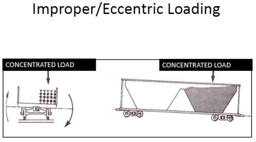
- Finally authors note that derailment is very often a result of a combination of several causes. Typical examples are
- Track twist, narrow curve with high cant and low train speed or train braking.
- Track twist and twisted or skew loaded wagons.
- Track geometry fault and strong compression forces in train due to poorly managed train composition or less than optimal train handling by the driver.
_______
Shannon carefully examines the various causes of derailments, and classifies them thus:—
(a) Incorrect gauge.
(b) Defects of surface, slacks and humps.
(c) Track out of alignment—“kick outs.”
(d) Unsuitable cant on curves.
(e) Curve worn rails.
(f) Broken rails.
(g) Points which may be open, or have a tendency to open.
(h) Defects in vehicles—defective springs, broken axles, worn or loose tyres.
(i) Difference in heights of coupled vehicles.
(j) Defects which may cause the frame of bogies to bind or catch on the main truck frame.
(k) Speed too high. The limitation of speed is due to sharp curvature, rough and weak track and unsuitable vehicles.
(l) Sudden application of brakes.
(m) Unequal distribution of the moveable load on the various wheels.
(n) Coupling of vehicles having different amount of overhang (shorts between bogies).
(o) Moving points when the train is passing over them.
(p) Propulsion of a heavy train round sharp curves.
_______
_______
The life of rails in track is determined primarily by:
- Wear – which occurs primarily on the gauge face of the high rails in the sharper curves, due to the high wheel flanging forces. Some wear also occurs on the running surfaces of all rails due to wheel/rail interaction and also due to rail maintenance (grinding).
- Plastic Flow – This can occur in both high and low rails, primarily in curves subjected to higher axle load operations (> 20 tonnes). Plastic flow is due to the applied wheel/rail contact stresses exceeding the strength of the material.
- Defects – which can develop in all rails (and welds), because of a wide range of reasons. Rail defects develop in any type of rail, or rail welds, as a result of several conditions. These conditions normally will originate from the rail manufacturing process; cyclical loading; and impact from rolling stock, rail wear, and plastic flow. There are many effects that influence rail defects and rail failure. These effects include bending and shear stresses, wheel/rail contact stresses, thermal stresses, residual stresses and dynamic effects. Defects are of major concern since, if not detected in time, they can grow and possibly cause rail failures, or at least necessitate expensive rail maintenance. The occurrence of rail defects has generally increased because of the much longer rail lives obtained through various improvements, which have reduced the rail wear and hence have allowed the defects to develop. A majority of the flaws found in rails are located in the head, however, flaws are also found in the web and foot. This means that the entire rail needs to be inspected.
These defects include
- Head and Web separation
- Foot and Web separation
- Horizontal and Vertical Split Web
- Bolt Hole Cracks
- Piped Rail
- Defective Welds
- Rail Corrosion
- Rail damage
_
Defects due to contact stresses or rolling contact fatigue (RCF):
‘Gauge corner cracking’ (cracks on the gauge corner) and ‘head checking’ (cracks on the head of the rail) are both examples of the more general phenomenon of rolling contact fatigue (RCF) which occurs in bodies in rolling contact. Such bodies can damage one another in various ways depending upon the severity of the contact pressure and the shear or ‘tearing’ forces in the area where the bodies come into contact. For most trains this ‘contact patch’ is about the size of a five pence coin, and the behaviour in this contact patch creates the forces between the wheel and rail that lead to RCF. Rolling contact fatigue can cause damage in the form of surface cracks by wearing away the rail, or through plastic flow of the materials. In the initial stages, RCF creates short cracks that grow at a shallow angle, but these can sometimes grow from a shallow to a steep angle. This ‘turndown’ tends to occur when cracks reach 30 mm in length, and at this stage the probability of rail fracture becomes much higher. Among the tools available for managing RCF, the most powerful ones continue to be development and adoption of improved rail steels, optimized wheel-rail profiles, friction management, and rail grinding.
________
Broken rails:
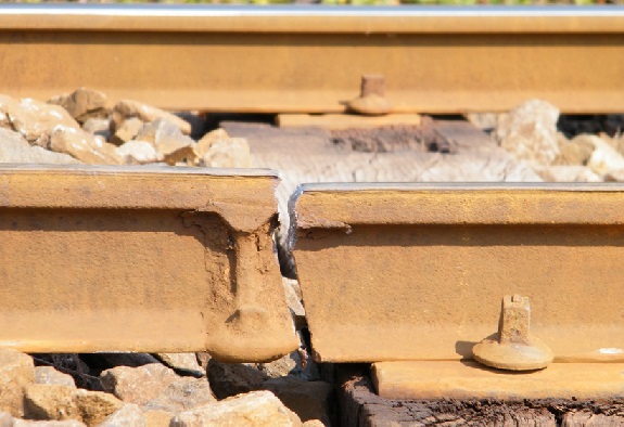
Broken Rail is a fracture of the rail in a running line including a broken joint or weld, or detachment of a piece from the rail which necessitates an immediate stoppage of traffic or the immediate imposition of a speed restriction lower than that currently in force. A traditional track structure consists of two rails, fixed at a designated distance apart (known as the track gauge), and supported on transverse sleepers (ties). Some advanced track structures support the rails on a concrete or asphalt slab. The running surface of the rails is required to be practically continuous and of the proper geometrical layout. In the event of a broken or cracked rail, the rail running surface may be disrupted if a piece has fallen out, or become lodged in an incorrect location, or if a large gap between the remaining rail sections arises.
- In jointed track, rails are usually connected with bolted fishplates (joint bars). The web of the rail experiences large shear forces and these are enhanced around the bolt hole. Where track maintenance is poor, metallurgical fatigue can result in the propagation of star cracking from the bolthole. In extreme situations this can lead to a triangular piece of rail at the joint becoming detached.
- Metallurgical changes take place due to the phenomenon of gauge corner cracking (in which fatigue microcracking propagates faster than ordinary wear), and also due to the effects of hydrogen inclusion during the manufacturing process, leading to crack propagation under fatigue loading.
- Local embrittlement of the parent metal may take place due to wheel spin (traction units rotating driving wheels without movement along the track).
- Rail welds (where rail sections are joined by welding) may fail due to poor workmanship; this may be triggered by extremely cold weather or improper stressing of continuously welded rails, such that high tensile forces are generated in the rails.
- The fishplates (joint bars) in jointed track may fail, allowing the rails to pull apart in extremely cold weather; this is usually associated with uncorrected rail creep.
_
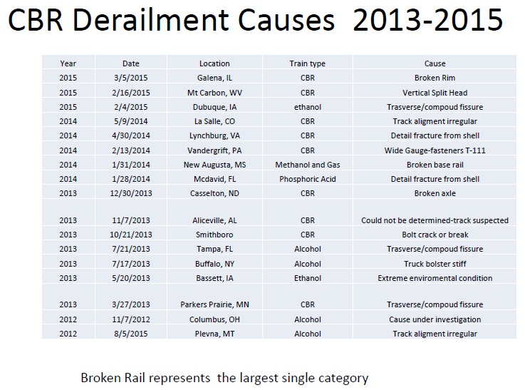
CBR means Crude By Rail, transporting crude oil by train. Broken rail represents the largest single category of CBR derailment.
_
Gauge widening:
Derailment may take place due to excessive gauge widening (sometimes known as road spread), in which the sleepers or other fastenings fail to maintain the proper gauge. In lightly engineered track where rails are spiked (dogged) to timber sleepers, spike hold failure may result in rotation outwards of a rail, usually under the aggravating action of crabbing of bogies (trucks) on curves. The mechanism of gauge widening is usually gradual and relatively slow, but if it is undetected, the final failure often takes place under the effect of some additional factor, such as excess speed, poorly maintained running gear on a vehicle, misalignment of rails, and extreme traction effects (such as high propelling forces). The crabbing effect referred to above is more marked in dry conditions, when the coefficient of friction at the wheel to rail interface is high.
_
Lack of maintenance:
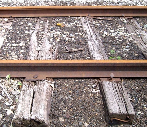
The problems in this piece of track include track that is badly out of alignment, cross-level across the rails is bad, less visible but significant are many rotted ties, consecutive ties missing spikes and loose joint bars. Also note the brush and lack of adequate drainage. Ballast was marginal with evidence of mud having leeched up at some joints.
_
Rotted cross ties:
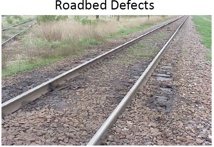
The evidence here is the standing spike on the right and a tie plate that has cut into the tie. On the left the tie plate is loose and there is a split radiating out from the spike along the center of the tie. Note the cinder ballast.
_
Head worn rail:
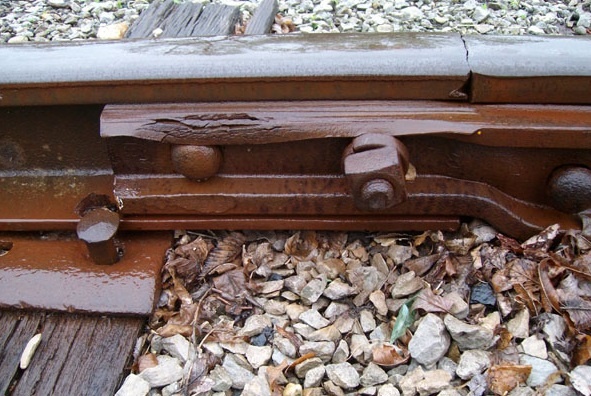
The rail on the left side of the joint has a worn head. It is obvious when looking at the top left of the joint bar. The lip of the joint bar is rolled down and torn by the flanges of passing cars actually riding on the flange instead of the rail head.
_
Rail end break:
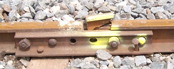
This rail broke out through a bolt hole. It happened to be on the field side of a curve and was an invitation for a derailment.
_
Failed joint:
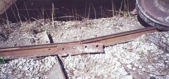
This joint failed under the weight of a passing train moving at walking speed. Note the rotted ties and missing track bolts. A few solid ties and four tight bolts could have avoided this problem. The car rolled over and its wheel is visible on the upper right.
_
Spread rail due to defective ties:
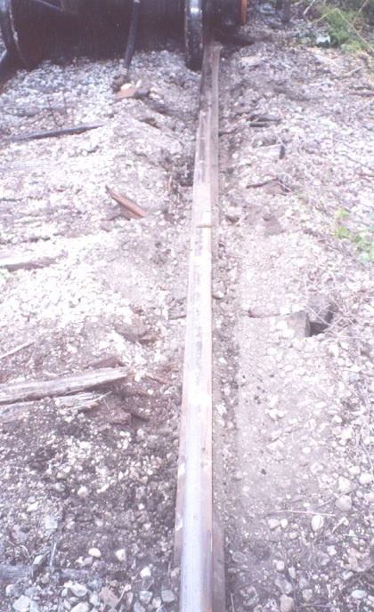
This is a rail that spread under a passing car. It was caused by defective ties. There is only one good tie in the photo, when there should be a majority of spike-holding ties. Note that a derailed car will cut through defective ties, this complicates rerailing efforts and adds to the overall expense.
_
Lubrication of moving parts of Vehicles:
There is no doubt that bogie centres and side bearers, horn cheeks, etc., should be well lubricated, but the claim that absence of lubrication does cause a derailment has not been proven, though, of course, lubrication does decrease the resistance to traction on curves and renders derailment less likely. It is principally on traversing curves that the benefit of lubricating the side bearers is felt.
__
Hogged Rails:
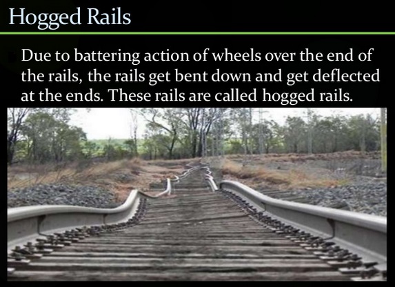
_
Kinks in Rails:
It is when the ends of adjoining rails move slightly out of position, “shoulders” or “kinks” are formed.
_
Buckling of Rails:
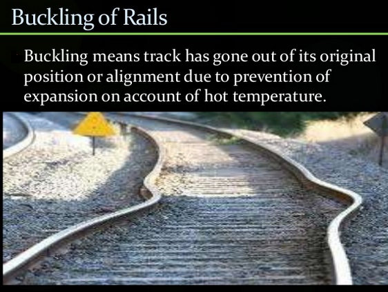
In hot weather the rail steel expands. This is managed by stressing continuously welded rails (they are tensioned mechanically to be stress neutral at a moderate temperature) and by providing proper expansion gaps at joints and ensuring that fishplates are properly lubricated. In addition, lateral restraint is provided by an adequate ballast shoulder. If any of these measures are inadequate, the track may buckle; a large lateral distortion takes place, which trains are unable to negotiate. Thermal expansion of long continuous sections of rail tracks is the driving force for rail buckling. This phenomenon resulted in 190 train derailments during 1998-2002 in the US alone. Earlier rails were laid with gaps in order to stop the rail buckling when it expanded when heated. Unfortunately, if the rail moves longitudinally through the shoes after repeated thermal expansion or much wear, the gaps close, and on the next really hot day the rail buckles and you have a derailment on the cards. American tracks tend to be continuous welded rail, which means that the quarter-mile steel tracks are welded together and tied down along the way. Longer tracks means trains can travel faster and smoother, give less friction between the train and the tracks, and are easier to maintain. Because the tracks don’t have a lot freedom to move, they’re tied down at high temperatures (95 – 100°F) to try and reduce the amount of expansion in the summer heat. When the rails are already heated by weather, the added energy from the train traveling over the tracks can be enough to cause them to become too hot. Since the rails are restricted from expanding along their length, they expand in the next easiest direction: out, causing buckling of rail. As temperatures rise and the tracks heat up, train companies want to reduce the amount of stress the rails are under. The load the train puts on the track (vertically) is dependent on the speed of the train, the diameter of the train’s wheels, and the weight that the train is carrying. To change the amount of vertical load on the track, the diameter of the wheels can’t change, nor can the weight of the train, so the only thing to change is the speed. So trains have to slow down when it is hot.
______
Defective wheels:
The running gear — wheelsets, bogies (trucks), and suspension — may fail. The most common historical failure mode is collapse of plain bearings due to deficient lubrication, and failure of leaf springs; wheel tyres are also prone to failure due to metallurgical crack propagation. Modern technologies have reduced the incidence of these failures considerably, both by design (specially the elimination of plain bearings) and intervention (non-destructive testing in service).
______
Unusual track interaction:
If a vertical, lateral, or crosslevel irregularity is cyclic and takes place at a wavelength corresponding to the natural frequency of certain vehicles traversing the route section, there is a risk of resonant harmonic oscillation in the vehicles, leading to extreme improper movement and possibly derailment. This is most hazardous when a cyclic roll is set up by crosslevel variations, but vertical cyclical errors also can result in vehicles lifting off the track; this is especially the case when the vehicles are in the tare (empty) condition, and if the suspension is not designed to have appropriate characteristics. The last condition applies if the suspension springing has a stiffness optimised for the loaded condition, or for a compromise loading condition, so that it is too stiff in the tare situation. The vehicle wheelsets become momentarily unloaded vertically so that the guidance required from the flanges or wheel tread contact is inadequate.
_____
Improper operation of control systems:
Junctions and other changes of routing on railways are generally made by means of points (switches — movable sections capable of changing the onward route of vehicles). In the early days of railways these were moved independently by local staff. Accidents — usually collisions — took place when staff forgot which route the points were set for, or overlooked the approach of a train on a conflicting route. If the points were not correctly set for either route — set in mid-stroke — it is possible for a train passing to derail. To prevent the unintended movement of freight vehicles from sidings to running lines, and other analogous improper movements, trap points and derails are provided at the exit from the sidings. In some cases these are provided at the convergence of running lines. It occasionally happens that a driver incorrectly believes s/he has authority to proceed over the trap points, or that the signaller improperly gives such permission; this results in derailment. The resulting derailment does not always fully protect the other line: a trap point derailment at speed may well result in considerable damage and obstruction, and even a single vehicle may obstruct the clear line.
_____
Derailment following collision:
If a train collides with a massive object, it is clear that derailment of the proper running of vehicle wheels on the track may take place. Although very large obstructions are imagined, it has been known for a cow straying on to the line to derail a passenger train at speed such as occurred in the Polmont rail accident. The most common obstructions encountered are road vehicles at level crossings (grade crossings); malicious persons sometimes place materials on the rails, and in some cases relatively small objects cause a derailment by guiding one wheel over the rail (rather than by gross collision). Derailment has also been brought about in situations of war or other conflict, such as during hostility by Native Americans, and more especially during periods when military personnel and materiel was being moved by rail.
_______
Harsh train handling and human error:
The handling of a train can also cause derailments. The vehicles of a train are connected by couplings; in the early days of railways these were short lengths of chain (“loose couplings”) that connected adjacent vehicles with considerable slack. Even with later improvements there may be a considerable slack between the traction situation (power unit pulling the couplings tight), and power unit braking (locomotive applying brakes and compressing buffers throughout the train). This results in coupling surge. More sophisticated technologies in use nowadays generally employ couplings that have no loose slack, although there is elastic movement at the couplings; continuous braking is provided, so that every vehicle on the train has brakes controlled by the driver. Generally this uses compressed air as a control medium, and there is a measurable time lag as the signal (to apply or release brakes) propagates along the train. If a train driver applies the train brakes suddenly and severely, the front part of the train is subject to braking forces first. (Where only the locomotive has braking, this effect is obviously more extreme). The rear part of the train may overrun the front part, and in cases where coupling condition is imperfect, the resultant sudden closing up (an effect referred to as a “run-in”) may result in a vehicle in tare condition (an empty freight vehicle) being lifted momentarily, and leaving the track. This effect was relatively common in the nineteenth century.
_
On curved sections, the longitudinal (traction or braking) forces between vehicles have a component inward or outward respectively on the curve. In extreme situations these lateral forces may be enough to encourage derailment. A special case of train handling problems is overspeed on sharp curves. This generally arises when a driver fails to slow the train for a sharp curved section in a route that otherwise has higher speed conditions. In the extreme this results in the train entering a curve at a speed at which it cannot negotiate the curve, and gross derailment takes place. The specific mechanism of this may involve bodily tipping (rotation) but is likely to involve disruption of the track structure and derailment as the primary failure event, followed by overturning. An example of speeding on a curve would be the May 2015 Philadelphia train derailment involving an Amtrak train traveling at 106 mph (171 km/h), twice the maximum allowable speed of 50 mph (80 km/h).
_
Human Error:
2012 research from the Transportation Research Record showed that broken welds, or rails, were a leading cause of derailment on main tracks, but human error was more likely to lead to derailment on siding tracks or train yards. Human error can include:
- inadequate braking operations,
- improper handling of the train
- failure to use switches properly
- Engineer distraction and negligence
- Excessive speed
These kinds of errors were most common at speeds of less than 10 miles per hour, although speeding was also a leading problem involving operator error. When the train operates at faster than 25 miles per hour, human error causes typically disappeared and equipment failures reigned supreme instead. Most common for equipment failure were broken wheels, journal and axle defects, and bearing failure. Most operator error derailments have a chain of events leading up to them. They may start with something as simple as fatigue, which leads to less alertness, poor judgement, and slower reaction time. Eventually minor problems become major incidents because the operator fails to recognize problems and take corrective action. Stress can also induce some of this. Overall, few operator error incidents are caused by incompetence, but rather by fatigue, stress, or distractions.
_______
Natural disaster: floods, landslides, rock slides, washouts, tornadoes etc. can cause derailment:
Derailment due to flooding:
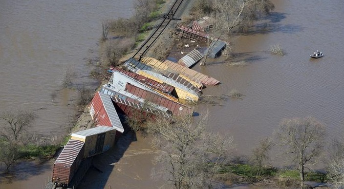
______
Weather:
Many factors can cause an accident, from too great a speed to operator fatigue. We won’t know the cause of the most recent ones until investigations are complete, but weather may be a factor. When it is very cold, as it has been across much of North America/ Europe/Russia, steel rails and train car wheels can contract and become brittle. If the steel has a manufacturing flaw, no matter how small, it can spread rapidly in the cold weather. You get real cold weather and a rail can just snap … a wheel will shatter like a piece of glass.
_
High number of cracks reported by Southern Railway in India attributed to huge swing in temperatures:
Southern Railway has recorded the maximum number of rail fractures in the country raising concern over the safety of train operations. Official data (up to May 2016) reveal that the zone reported 43 rail fractures and three accidents. Though timely intervention of engineers and engine drivers has contributed immensely in detecting and rectifying rail fractures, the menace, some railway officials say, remains a threat to safety. While a simple crack may not be of much concern, a fracture causing separation of the track could lead to derailment of trains. Engineers say extreme weather condition is the primary reason for rail fractures. While the track breaks due to linear expansion in summer, the same happens in winter due to contraction. Tamil Nadu has hot weather conditions almost all through the year. The difference between the highest and lowest temperature in 24 hours has an impact on the rails. In many States, winters remain cold all through the day. In this State, the temperature is high during the day and drops in the night…the wide variation in numbers can cause the cracks.
_
The Power of Wind:
Can winds actually cause a freight train to derail?
With the winds blowing roughly from north to south, and the train tracks running east to west, the winds would exert the maximum amount of force against the north sides of the box cars. If the strong winds were already blowing against the side of the train to start, and then a gale-force wind from a storm-outflow derecho struck the side of the train as well, it could easily have destabilized the entire line and spilled it off the tracks. NOAA scientists have examined several incidences, with ones in Kansas in May 2014, Texas in 2013, and North Dakota in 2006, just as a few examples. Strong winds – from 60-80 miles per hour – with sudden changes in wind direction, played a major role. Your average box car from a freight train, even if it’s empty, represents 20-30 tons worth of steel. That’s a lot especially when you string 30 of them together and add an even heavier locomotive to the front (and possibly back as well). The train’s weight certainly would help it stay on the tracks, but 30+ rail cars represent a lot of surface area to push against, especially when the blasts of wind can potentially affect the entire length of the train all at once.
______
______
Mechanics and Mechanism of derailment:
Since the inception of the railway in England in 1825, train derailment has been a problem troubling railway scientists and technologists alike. Train derailment, which occurs frequently in many countries of the world, has become a centennial problem. One reason is insufficient understanding of the mechanics of derailment, which means feasible precaution measures are not taken. Since the launch of the speed-up campaign in the Chinese railways, the operation speed of the freight trains has increased from 50–60 km/hr to 80 km/hr. Proportionately, more and more derailment accidents have taken place, particularly on straight lines, constituting a grave threat to safety and a serious interference to the normal order of railway transportation.
_
Understanding the science behind trains can help identify the causes of accidents—and lead us to safer railways. Many factors influence the cause of derailments. In the field of vehicle engineering, these are axle load, imbalance between the right and left-side static wheel loads, spring constants of the primary and secondary suspensions, the height of the vehicle center-of -gravity and so on. In the field of track engineering, curve radius, superelevation, twist, track irregularities and so on. Beside these factors, the friction coefficients between the wheels and each rail in both the tread and flange areas, and the train speed also play important roles.
_
It’s extremely difficult to derail a train. Due to sheer weight it hard to derail them, but remember this when parked next to a track waiting to cross as a train is coming through. They are not bolted or attached to the wheels at all. They sit on a 7 to 10 inch king pin, and the weight is all that keeps them on. Empty rail cars are very easy to derail. Back up a few feet from the cross guards and give the tracks some space. It can sometimes take over a mile to brake a locomotive. Stopping/starting trains is an arduous process compared to something like a car, and because of that momentum, it makes it impossible for an engineer to stop a locomotive in time when a car is parked on the tracks or if someone stumbles on to them.
_____
There are two broad categories of derailment:
- Sudden derailments: Instant dismounting of wheel from rail.
- Gradual derailments: Gradual climbing of flange on the rail.
_
Sudden derailments:
When derailing forces are quite high on a wheel, it may suddenly jump off from the rail table and the rolling stock derails. In this case, no flange mounting marks are available on the rail table. However the wheel drop marks can be seen on ballast or sleepers.
The possible causes for a sudden derailment are:
- Sudden shifting of load
- Improper loaded vehicle
- Excessive speed on curve or turn out
- Sudden variation in draw bar forces induced due to improper train operations (sudden braking or acceleration)
- Broken wheels/springs or suspension gear components.
- Failure of track or vehicle component
- Obstruction on track.
_
Gradual Derailments (Mounting of wheel flange):
On the track, the wheel flange travels performing lateral movements as well due to clearances between rail face and wheel flange. If the derailment occurs due to climbing of wheel flange, the derailing wheel first rubs with the inside face of the rail and grazing/rubbing marks are seen on the inside edge of one of the rails. Thereafter due to excessive lateral flange forces, wheel flange mounts on the rail table and drops on the other side causing derailment. In this type off accident, wheel flange mounting marks are also clearly visible on the rail.
_______
Derailing on curves:
Before reaching the overturning speed, a slow, heavy freight train is far more likely to derail on a curve by rail rollover, wide gage, or wheel climb.
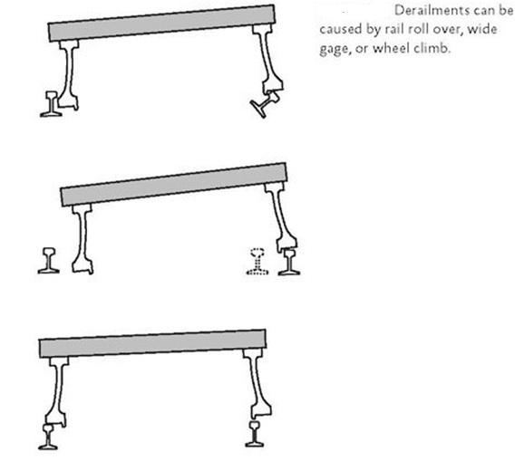
_
Wheel climb (flange climb derailment):
It is the process of a flange climbing up and often off the inside or gauge side of the rail. It is a major source of derailments. Wheel climb is more likely to occur in curves with wheels whose flanges are worn or have improper angles. “Wheel climb derailments,” also occur when a train moves through switches. When switches or wheels are damaged due to excessive wear and tear, the wheel and switch point misalign — often resulting in derailments. Proper rail lubrication as well as the use of guard rails and switch point protectors can also minimize the risk of derailments.
_
The tracks are constantly moving around (and constantly being readjusted) because of settlement and train forces. The track spikes do not prevent the rails from overturning but do keep them from spreading. Rail overturning is thwarted by the downward wheel forces. If the wooden cross ties are rotted, inertial loading on curves may widen the rails.
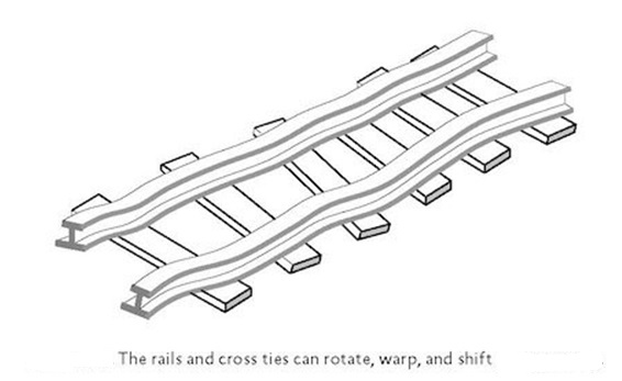
_
Standards are established for maximum distance between rails (gauge), maximum dips in each rail (profile), and maximum deviation from straightness (alignment). Higher classes of track require tighter requirements to operate safely at higher speeds. For example, freight trains are limited to 40 mph (64 km/h) on Class 3 track and 60 mph (97 km/h) on Class 4 track. Although track geometry today is measured automatically with high-speed cars using laser sensors, the standards are based on low-tech methods of measuring the deviation from a 62-foot (18.8-m) string pulled tight. Every 62 feet (18.8 m) of Class 3 track can deviate up to 1.5 inches (3.8 cm) from straight and dip up to 2.25 inches (5.7 cm). The Acela operates at 150 mph (241 km/h) on Class 8 track. Every 31 feet (9.4 m) of Class 8 track can deviate up to 0.5 inch (1.27 cm) from straight and dip up to 1 inch (2.54 cm). For all trains operating above 125 mph (201 km/h), at least one train per day has sensors to measure, quantify, and record the location of any rough track. Concrete, instead of wood, is used for ties on Class 8 track. The concrete is less susceptible to shifting and water damage. At least once annually Class 8 track gage stability is checked with a special car that loads the rail sideways with a force of 10,000 lbs (44.5 kN). Class 8 track is also inspected twice a year with ultrasonic sensors for internal fatigue cracks.
______
Overturn derailment and flange climb derailment at curves:
“Train overturn derailments” are different phenomena from “flange climb derailments” and they are rather simple phenomena, but it is very important to grasp the basic phenomena and to recognize the safety limit against them. The vehicle is overturned when the curving speed exceeds the speed limit, where the resultant force vector composed by the centrifugal force, the gravity and the inertial force of lateral vibration goes toward outside of the track from the gravity center of the vehicle. Therefore “Overturn” is different phenomena from “flange climb”, and the lateral contact forces between wheel and rail rarely influence to the overturn movement of the vehicle.
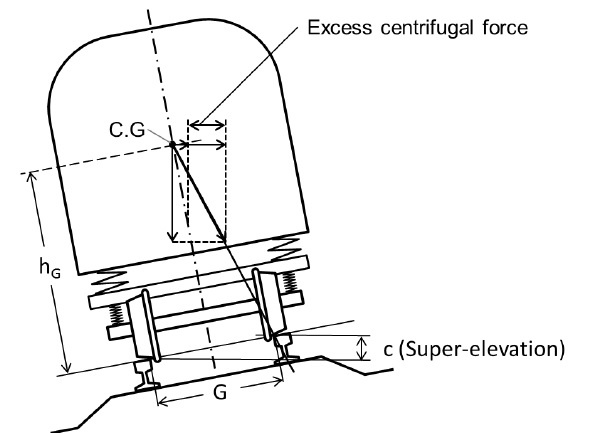
_
“The leading vehicles of the train at the entrance of curve” or “the trailing vehicles of the train at the exit of curve” are overturned. The high gravity center vehicles are easy to overturn. The critical speed is heavily influenced by the ratio of “C.G height of the vehicle” to “track gauge width”.
___
Too fast on a curve:
The derailment typically occurs where there is a curve. The safe speed is determined by the curve radius and the height difference between the inner and the outer rail. It works similar to a car. A moving vehicle has inertia and wants to continue to move in a straight line. At a curve something forces it to change direction. The higher the speed, the stronger this force needs to be. If the force is not strong enough, the vehicle can’t follow the curve. The car will go off the road, the train will derail. If the centrifugal inertial loading is excessive, the locomotive begins to tip. The flange of the wheel catches on the rail and the locomotive starts to rotate, as shown in figure below.
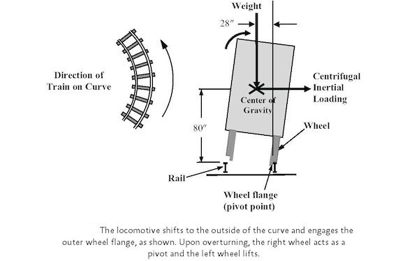
In fact, that’s why the flanges are on the inside of the wheels. If the flanges were on the outside, the slightest bit of wheel lift would slide the locomotive off the tracks.
___
Too slow on curve:
If the railroad car is made top heavy and the right wheel is lifted enough (even at zero mph), eventually the car tips over counter-clockwise. The car tips over at zero mph when the weight load points outside the inner rail, as shown in the figure below:
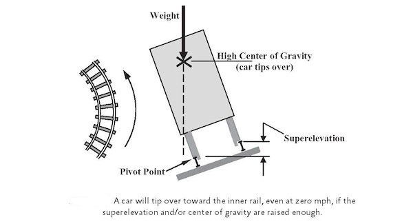
_
On curves the outer rail is elevated so that, at a certain critical speed, the centrifugal force is balanced and the load on all the wheels is equalised. The speed under which this condition takes place will be called normal speed. When the truck is passing over the curve at normal speed the load is carried on the centre bearing and the bogies are free to swivel. If the speed is greater than normal the truck will tilt outward, and if it is less than the normal the car will tilt inward. In both of these cases the side bearers toward which the truck tilts assist the centre bearing to carry the weight of the truck body. This pressure on the side bearings grips the truck and prevents it from swivelling freely.
_
When the truck enters a curve, the front wheels being on a partially elevated track and the rear wheels on a level track, it is subjected to a severe twist, and if the framing is rigid the load is carried by two side bearings diagonally opposite each other. (Where vehicles such as passenger coaches have good springing and long bodies and are therefore more or less flexible, this does not result, but on short trucks and tenders where the distance between the wheel centres is comparatively short, it holds true.) There is a tendency for wheels to climb the rail of curves, and the only reason that wheels do not climb in their effort to swivel the truck around the curve is because of the excessive vertical load which comes on them.
_
Stucki examines at great length the action of trucks passing through curves (a) entering, (b) passing, (c) leaving, and in conclusion arrives at:
(1) That curves should be maintained true curves, and that there should be sweet transition from curve to curve and curve to straight, and that great attention should be paid to super-elevation.
(2) Under normal conditions there would be no pressure between wheel flanges and rails.
(3) That where track or truck imperfections exist there are, in every curve, at least six points where there is a danger of wheels climbing the rail.
(4) Therefore, to minimise these tendencies, it is advisable to make the side bearings as frictionless as possible.
As a distinguished engineer has said, the great majority of derailments can be traced back to imperfections in the track surface, and that variations in cross level do produce lateral oscillations of the vehicles which, if not absorbed in the springs, must result in derailment. The best protection against derailments is good track.
__
The causes of the excess of curving speed are different among various accidents.
For example,
a) too early acceleration at the exit of curve,
b) driver’s snooze,
c) driver’s misunderstanding of safety limit of curving speed,
d) braking delay.
It is important to take appropriate countermeasures for each cause, but it is also important to design vehicles and infrastructure, taking train running speed plan into consideration for securing the safety margin against train overturn.
_______
Flange climb (wheel climb) derailment on outer rail:
L/V ratios:
The tendency to derail is often described by the L/V ratio, where L is the lateral force and V is the vertical force at the wheel-track interface, as shown in the figure below:
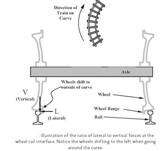
The value of L is determined by the load on both wheels of the wheelset multiplied by the coefficient of friction, plus the centrifugal force. In Japan, the “climbing-up derailments” on sharply curved track have been studied in detail after the “Tokyo subway Nakameguro accident”, and the report by the investigation committee indicates that (1) the derailment coefficient L/V depends heavily upon the friction coefficient, and (2) the friction coefficient changes every moment according to the conditions present. But the sliding on the wheel on the low rail is not lateral — the wheel tread is actually sliding backwards (i.e. rotating less rapidly than the forward speed requires) and the lateral friction force generated is limited by the vector of the sliding action.
_
The higher the L/V ratio, the more likely the car is to derail.
There are rough guidelines for L/V limits.
Wheel climb may occur if:
L/V greater than 1 for new freight cars with new wheels on new, straight track
L/V greater than 0.82 may be unstable on curves
L/V greater than 0.75 can be unstable for worn wheels and worn rail
L/V greater than 0.68 may overturn a poorly constrained rail
Rails spaced too close together can also encourage wheel climb.
The stated L/V ratios are merely rules of thumb, not rigid predictors. There are many other factors that interact, such as the condition of the trucks, rails, and wheels and whether or not the car body is bouncing on its suspension.
The L/V ratio can also vary greatly as the wheels and rail wear and as the contact location changes. A worn rail on the outside of a curve is shown in the figure below.
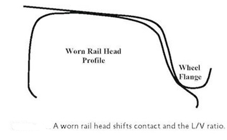
_
The guidance system of practical railway vehicles relies on the steering effect of the conicity of the wheel treads on moderate curves (down to a radius of about 500 m, or about 1,500 feet). On sharper curves flange contact takes place, and the guiding effect of the flange relies on a vertical force (the vehicle weight). A flange climbing derailment can result if the relationship between these forces, L/V, is excessive. The lateral force L results not only from centrifugal effects, but a large component is from the crabbing of a wheelset which has a non-zero angle of attack during running with flange contact. The L/V excess can result from wheel unloading, or from improper rail or wheel tread profiles. Wheel unloading can be caused by twist in the track. This can arise if the cant (superelevation) of the track varies considerably over the wheelbase of a vehicle, and the vehicle suspension is very stiff in torsion. In the quasi-static situation it may arise in extreme cases of poor load distribution, or on extreme cant at low speed. If a rail has been subject to extreme sidewear, or a wheel flange has been worn to an improper angle, it is possible for the L/V ratio to exceed the value that the flange angle can resist.
_
Recently, flange-climb derailments of light-weight commuter trains on tight curves at low speed have tended to increase. This leads to a need for establishing safety evaluation methods against flange-climb derailments. To estimate the level of safety against flange-climb derailment, we traditionally use the “derailment coefficient” known as “Nadal’s equation”. When the derailment coefficient is smaller than the calculated value by Nadal’s equation, we judge that there is no risk of flange-climb derailment. On the other hand, in some cases, time-series computer simulations based on vehicle dynamics model may be used to calculate the derailment coefficients for various scenarios. However, because this method needs long calculation time, it is not suitable to evaluate many cases that consist of combinations of numerous conditions.
_
The Nadal formula, also called Nadal’s formula, is an equation in railway design that relates the downward force exerted by a train’s wheels upon the rail, with the lateral force of the wheel’s flange against the face of the rail. This relationship is significant in railway design, as a wheel-climb derailment may occur if the lateral and vertical forces are not properly considered.
_
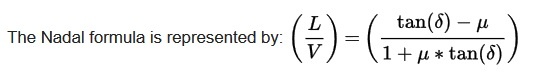
In this equation, L and V refer to the lateral and vertical forces acting upon the rail and wheel, δ is the angle made when the wheel flange is in contact with the rail face, and μ is the coefficient of friction between the wheel and the rail.
_
Typically, the axle load for a railway vehicle should be such that the lateral forces of the wheel against the rail should not exceed 50% of the vertical down-force of the vehicle on the rail (L/V 0.5). Put another way, there should be twice as much downward force holding the wheel to the rail, as there is lateral force which will tend to cause the wheel to climb in turns. This ratio is accomplished by matching the wheelset with the appropriate rail profile to achieve the L/V ratio desired. If the L/V ratio gets too high, the wheel flange will be pressing against the rail face, and during a turn this will cause the wheel to climb the face of the rail, potentially derailing the railcar.
_
The Nadal formula assumes the wheel remains perpendicular to the rail—it does not take into account hunting oscillation of the wheelset, or the movement of the wheel flange contact point against the rail. A variation of the Nadal formula, which does take these factors into consideration, is the Wagner formula. As the wheelset yaws relative to the rail, the vertical force V is no longer completely vertical, but is now acting at an angle to the vertical, β. When this angle is factored into the Nadal formula, the result is the Wagner formula. Nadal’s quotient has been widely adopted in the assessment of the risk of a derailment. Although recent studies have sometimes criticized that criterion, it still serves as the basis of new criteria and regulations.
______
Wheel-rail interaction vis-à-vis flange climb derailment:
Nearly all practical railway systems use wheels fixed to a common axle: the wheels on both sides rotate in unison. Tramcars requiring low floor levels are the exception, but much benefit in vehicle guidance is lost by having unlinked wheels. The benefit of linked wheels derives from the conicity of the wheel treads—the wheel treads are not cylindrical, but conical. On idealised straight track, a wheelset would run centrally, midway between the rails.
_
The example shown below uses a right-curving section of track. The focus is on the left-side wheel, which is more involved with the forces critical to guiding the railcar through the curve.
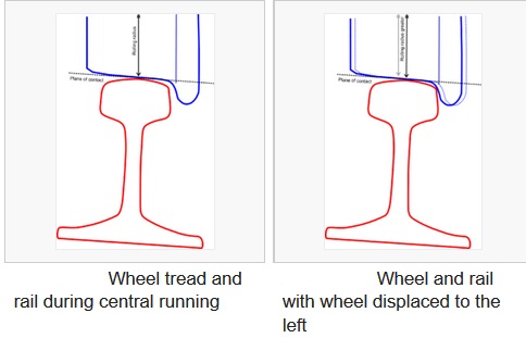
Diagram above left shows the wheel and rail with the wheelset running straight and central on the track. The wheelset is running away from the observer. (Note that the rail is shown inclined inwards; this is done on modern track to match the rail head profile to the wheel tread profile.) Diagram above right shows the wheelset displaced to the left, due to curvature of the track or a geometrical irregularity. The left wheel (shown here) is now running on a slightly larger diameter; the right wheel opposite has moved to the left as well, towards the centre of the track, and is running on a slightly smaller diameter. As the two wheels rotate at the same rate, the forward speed of the left wheel is a little faster than the forward speed of the right wheel. This causes the wheelset to curve to the right, correcting the displacement. This takes place without flange contact; the wheelsets steer themselves on moderate curves without any flange contact. The sharper the curve, the greater the lateral displacement necessary to achieve the curving. On a very sharp curve (typically less than about 500 m or 1,500 feet radius) the width of the wheel tread is not enough to achieve the necessary steering effect, and the wheel flange contacts the face of the high rail.
__
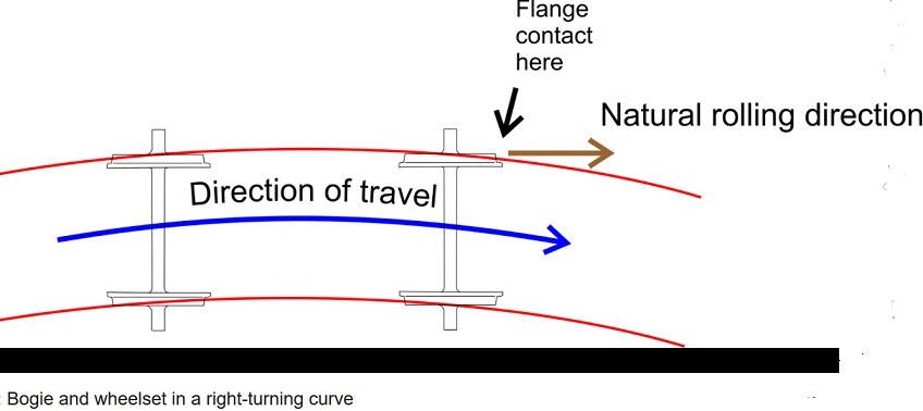
Diagram above shows the running of wheelsets in a bogie or a four-wheeled vehicle. The wheelset is not running parallel to the track: it is constrained by the bogie frame and suspension, and it is yawing to the outside of the curve; that is, its natural rolling direction would lead along a less sharply curved path than the actual curve of the track. The angle between the natural path and the actual path is called the angle of attack (or the yaw angle). As the wheelset rolls forward, it is forced to slide across the railhead by the flange contact. The whole wheelset is forced to do this, so the wheel on the low rail is also forced to slide across its rail. This sliding requires a considerable force to make it happen, and the friction force resisting the sliding is designated “L”, the lateral force. The wheelset applies a force L outwards to the rails, and the rails apply a force L inwards to the wheels. Note that this is quite independent of “centrifugal force”. However at higher speeds the centrifugal force is added to the friction force to make L. The load (vertical force) on the outer wheel is designated V, so that in figure below the two forces L and V are shown.
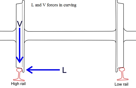
The steel-to-steel contact has a coefficient of friction that may be as high as 0.5 in dry conditions, so that the lateral force may be up to 0.5 of the vertical wheel load.
_
During this flange contact, the wheel on the high rail is experiencing the lateral force L, towards the outside of the curve. As the wheel rotates, the flange tends to climb up the flange angle. It is held down by the vertical load on the wheel V, so that if L/V exceeds the trigonometrical tangent of the flange contact angle, climbing will take place. The wheel flange will climb to the rail head where there is no lateral resistance in rolling movement, and a flange climbing derailment usually takes place. In figure below left the flange contact angle is quite steep, and flange climbing is unlikely. However, if the rail head is side-worn (side-cut) or the flange is worn, as shown in figure below right the contact angle is much flatter and flange climbing is more likely.
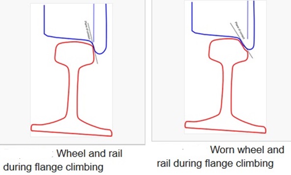
_
Once the wheel flange has completely climbed onto the rail head, there is no lateral restraint, and the wheelset is likely to follow the yaw angle, resulting in the wheel dropping outside the rail. An L/V ratio greater than 0.6 is considered to be hazardous. It is emphasised that this is a much simplified description of the physics; complicating factors are creep, actual wheel and rail profiles, dynamic effects, stiffness of longitudinal restraint at axleboxes, and the lateral component of longitudinal (traction and braking) forces.
_______
Sudden Application of Brakes and derailment:
Shannon, in his work on Derailments, disposes most thoroughly of this theory as a cause of derailments. If thought were given to the thousands of times yearly, on most railways, that sudden applications of the brakes are made, without any ill effect resulting, this theory would be ruled out as a causative factor in derailments. But it is extraordinary how widespread is this theory of bunching (always coupled with a sudden application of the brakes), and how persistently it is advanced without a shred of supporting evidence. Shannon says, and says correctly, that when the vacuum brake has been applied throughout the train, if all the brakes are adjusted alike so that each vehicle is retarded by a force proportional to its weight, no vehicle will have any effect on any other in the train. Although such a nice adjustment cannot be expected in practice, yet under working condition when all brakes are on throughout the train, one vehicle will exert but little pull or push on another. When the brake is being applied it acts so quickly that even under the most favourable conditions the speed of the vehicle in front will not be retarded more than two miles per hour before the brake acts on the vehicle behind it. While this difference in speeds will, no doubt, result in a slight shock (if the train is running with loose couplings at the time of the application of the brakes) and slight tendency to derailment on a curve, it is most unlikely to be the sole cause of a derailment; more severe shocks are caused by banking engines pushing a train in the rear in ordinary operations or when steam is shut off and an engine is allowed to “drift.” What Shannon means, in simple words, is that the application of the brake throughout the train is to all intents and purposes instantaneous on each vehicle. Tests on 200 axles have given a complete application throughout in 3 1/2 seconds—this leaves little time for crowding. The shocks caused by a sudden application of the engine brake must be greater than those caused by an application of the vacuum brake; yet, Shannon says, he could not trace one case in which the Board of Trade officers have ascribed a derailment to this cause. Others have also examined many Board of Trade accident returns and cannot find “Brake Application” even mentioned in this connection. The so called “bunching” derailments really result from oscillation brought about by track irregularities and defective springs; this, of course, apart from positive defects in tracks or trucks.
________
Brake failure and derailment:
One common misconception is that brake failures often lead to derailments. This is almost never the case. Airbrakes, which all freight trains use, are designed to work the opposite the way the brakes in your car work. It takes energy to turn the brakes off. In action, airbrakes work like this: Each train car has its own isolated tank of air, which squeezes that car’s brakes. When the train is running, these air tanks are always on, trying to clamp the brakes tight. To make the car move, the main brakeline— an independent system—pumps air to counteract those air tanks and release the brakes. That sounds inefficient, but the idea is that in the event of a malfunction of the main airbrake line—if it breaks open, for example—all the brakes will squeeze against the wheels, violently stopping the train rather than letting it run away. The only way an airbrake failure can lead to a derailment is if the train had been left on the tracks without its emergency brakes on—and for many hours—while the train car’s individual air tanks inevitably leaked air. It’s a farfetched scenario, but it has happened.
_______
Turnout (railroad switch/point) related derailment:
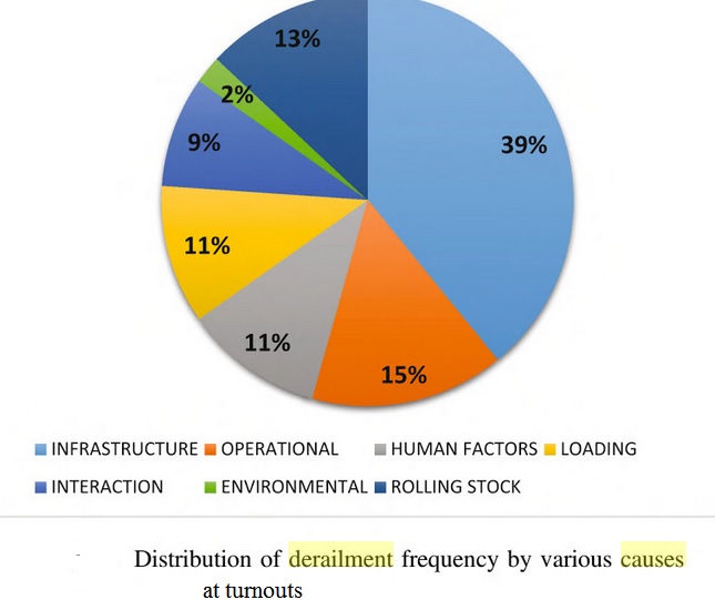
Far more common is moving too fast on a turnout. On a turn-out the track crosses over with sharp turns to merge onto a parallel track. The engineer must slow the train for the turnout or risk overturning. Turnout-related derailments collectively cause almost the half of all train derailments in the UK. Understanding what types of causes contribute to derailments at turnouts is highly likely to provide the fundamentals for preventing such accidents as well as developing cost-effective maintenance strategies. This also results in reducing railway transportation risk, allowing the railway operators to sustain a smooth operation. In railway engineering, the term turnout is used to describe a mechanical installation by means of which flanged vehicles are able to be diverted from one track to another. Although turnouts have a close similarity in their design and method of installation, the engineering process in building their constituents may be vastly different, giving rise to their complexity.
_______
Slippery rail:
Slippery rail or low railhead adhesion, is a condition of railways (railroads) where contamination of the railhead causes trains to experience less adhesion (grip). This can lead to wheelslip when the train is taking power, and wheelslide when the train is braking. The most common cause of contamination is fallen moist leaves that lie on and cling to the top surface of the rails of railway tracks. The condition results in significant reduction in friction between train wheels and rails, and in extreme cases can render the track temporarily unusable. In Britain, the situation is colloquially referred to as “leaves on the line”. In the United Kingdom, it was estimated that the autumn leaves problem cost the rail industry GBP 60 million (USD 115 million) a year.
_
The loss of friction between wheels and rail results in loss of tractive force — the wheels begin to spin, and in some instances the train is unable to move. In braking, substantial loss of friction results in reduced braking force. Braking distances are considerably longer, and in extreme cases the wheels may even lock up, causing the train to slide. Modern locomotives and multiple units are equipped with Wheel slide protection to counter slippery rail conditions. Locked wheels can self-grind flat spots on the steel tyres, especially if the wheels are still sliding when arriving at a non-greasy section of rail, e.g. one that has previously been sanded. This causes the wheels to go out of profile (known colloquially as ‘wheel flats’), which subsequently leads to severe vibration and the need for the wheels to be re-profiled or re-tyred at great expense. In extreme cases, the build-up of leaf material can electrically insulate the wheels from the rails, resulting in a failure of signalling equipment to detect the presence of the train. Where the problem is severe, Track Circuit Actuators fitted to trains can help alleviate the problem.
_
Low adhesion can also be caused by crushed insects resulting in derailment:
There are many substances which can cause low adhesion when they are deposited on the railhead. In Victoria, Australia, train wheels crushing plagues of introduced Portuguese millipedes which were crossing the tracks, caused passenger rail operator V/Line to be penalised more than $700,000 for cancellations and poor punctuality in one quarter of 2001. In 2009, railway tracks at Tallarook in central Victoria were also affected by a Portuguese millipede plague, causing several trains to be cancelled. The crushing of Portuguese millipedes is suspected to have caused a crash between two trains at Clarkson near Perth, Western Australia, in September 2013. Slippery rails caused by caterpillars were reported in Queensland in 1938. Crushed locusts affected train operations on the Otavi Mining and Railway Company in German South-West Africa (modern Namibia) in 1924.
_
Mitigation measures for slippery rail:
Treatment measures generally involve some system to jet or blast the accumulated deposit away, or to coat it with a high-friction material. Blasting is usually carried out with water jets, often in combination with mechanical scrubbing apparatus. The coating method usually involves depositing sand in a paste on to the rail; as the sand may exacerbate the risk of unwanted insulation, the sand mix sometimes contains metal particles. The coating is applied from special trains. Locomotives and Multiple units are fitted with sanders which apply a fine layer of dry sand on the railhead. This assists adhesion during braking and acceleration. Wheel Slide Protection (WSP) equipment is fitted to passenger trains to manage the behaviour of wheel sets in low adhesion conditions. When the train is braking, it behaves like the ABS system (anti-skid braking system) in cars by releasing the brake on any axle if it detects that it is locking up. WSP can also control the traction system to prevent wheel spin when applying power. Where trains have difficulty stopping during low adhesion conditions the greatest risk is of passing a signal at danger or ‘over running’ a station. At these times train drivers adopt ‘defensive driving’, which involves braking earlier and more gently than usual. Also less power is applied when starting trains.
______
Can a Coin placed on the tracks derail a train?
No.
As far as a coin is concerned, its size and mass is not significant enough to cause a train to run off the rail. In short, the coin will have no effect at all. In fact the coin the will be flattened and stick to the track. In other cases, the coin is nowhere to be seen; it gets stuck to the wheels and simply fly out at harmful speeds. Trains don’t care much about anything on the tracks. Stones are reduced to dust. Coins are reminted. People and animals are exploded like meat filled balloons. A really big rock does have the capacity to derail the train, but for that you will have to ensure that the rock is of high structural integrity like granite and not lime stone or red stone. That done, now you will have to arrange for the transportation of that big, 8-10 ton to be kept on both the rails as this will generate the required jolt to take the train down.
_______
_______
Some examples of derailments with underlying causes and mechanisms:
_
- Primary mechanical failure of a track component:
In the Hatfield rail crash in England in 2000, which killed four people, rolling contact fatigue had resulted in multiple gauge corner cracking in the surface; 300 such cracks were subsequently found at the site. The rail cracked under a high speed passenger train, which derailed. In the earlier Hither Green rail crash, a triangular segment of rail at a joint became displaced, and lodged in the joint; it derailed a passenger train and 49 persons died. Poor maintenance on an intensively operated section of route was the cause.
_
- Primary mechanical failure of a component of the running gear of a vehicle:
In the Eschede train disaster in Germany, a high speed passenger train derailed in 1998, killing 101 people. The primary cause was the fracture from metal fatigue of a wheel tyre; the train failed to negotiate two sets of points and struck the pier of an overbridge. It was the most serious railway accident in Germany, and also the most serious on any high speed (over 200 kilometres per hour) line. Ultrasonic testing had failed to reveal the incipient fracture.
_
- Dynamic effects of vehicle – track interaction:
In 1967 in the UK there were four derailments due to buckling of continuously welded track (CWR): at Lichfield on 10 June, an empty carflat train (a train of flat cars for transporting automobiles); on 13 June an express passenger train was derailed at Somerton; on 15 July a freightliner train (container train) was derailed at Lamington; and on 23 July an express passenger train was derailed at Sandy. The official report was not entirely conclusive as to the causes, but it observed that the annual total of buckling distortions was 48 in 1969, having been in single figures in every previous year, and that [heat-related] distortions per 1,000 miles per annum were 10.42 for CWR and 2.98 for jointed track in 1969, having been a maximum of 1.78 and 1.21 in the previous ten years.
_
- Improper operation of control systems:
In the Connington South rail crash on 5 March 1967 in England, a signaller moved the points immediately in front of an approaching train. Mechanical signalling was in force at the location, and it was believed that he improperly replaced the signal protecting the points to danger just as the locomotive passed it. This released the locking on the points and he moved them to lead to a loop line with a low speed restriction. The train, travelling at 75 miles per hour (121 km/h), was unable to negotiate the points in that position and five persons died.
_
- Secondary events following collision:
A passenger train was derailed in the Polmont rail accident in the UK in 1984 upon hitting a cow at speed; the train formation had the locomotive at the rear (propelling) with a light driving-trailer vehicle leading. The cow had strayed on to the line from adjacent agricultural land, due to deficient fencing. 13 persons died in the resulting derailment.
_
- Train handling effects:
The Salisbury rail crash took place on 1 July 1906; a first class only special boat train from Stonehousepool, Plymouth England, ran through Salisbury station at about 60 miles per hour (97 km/h); there was a sharp curve of ten chains (660 feet, 200 m) radius and a speed restriction to 30 miles per hour (48 km/h). The locomotive overturned bodily and struck the vehicles of a milk train on the adjacent line. 28 people were killed. The driver was sober and normally reliable, but had not driven a non-stopping train through Salisbury before.
_
- Broken rail:
In February 2015, an oil train derailed in West Virginia, spilling nearly 400,000 gallons of oil, and forcing 1,000 evacuations. In the months following the accident, the National Transportation Safety Board (NTSB) determined the cause of the derailment to be a broken rail on the track. In one of the worst train accidents in the history of India, at least 150 people were killed and over 200 were injured when 14 coaches of Indore-Patna Express derailed at Pukhrayan near Kanpur on November 19, 2016. The intensity of the damage suggested that the train was at its peak speed. The Indore-Patna Express train derailment could have been reportedly caused by cracked tracks. This could be a fallout of “rail fracture”, reported The Times of India, which is caused by expansion and contraction of tracks with change in weather. Using improper fittings in tracks could also cause a fracture, according to the HT report.
_
- Human error and speed:
There have been several other derailments in the UK due to trains entering speed-restricted sections of track at excessive speed; the causes have generally been inattention by the driver due to alcohol, fatigue or other causes. Prominent cases were the Nuneaton rail crash in 1975 (temporary speed restriction in force due to trackwork, warning sign illumination failed), the Morpeth accident in 1984 (express passenger sleeping car train took 50 miles per hour (80 km/h) restricted sharp curve at full speed; alcohol a factor; no fatalities due to the improved crashworthiness of the vehicles). In May 2015, Amtrak 188 derailed in north Philadelphia, killing 8 people and injuring over 200 others. In the months after the accident, the NTSB found that the train was going over 100 miles per hour in an area with a speed limit of 50 miles per hour. The engineer was found to have been distracted at the time of the accident. The distraction led to the excessive speed at the time of the curve, which should normally be taken at a much lower speed. Human error and speed in particular, continues to be a common cause of train accidents and derailments throughout the world. In 2013, a train travelling from Madrid to Ferrol, in northwestern Spain, derailed just as it was about to enter the Santiago de Compostela station. At least seventy-eight people were killed, and dozens were injured. Video of the accident shows the train entering the curve at what seems to be a high speed; the passenger cars detach from the engine and derail, while the engine stays on the tracks for a few more seconds before it, too, leaves the rails and hits a wall. Unofficial reports claim that the train was going as fast as a hundred and twenty miles per hour on track rated for only fifty mph. Unlike Japan’s Shinkansen or France’s T.G.V., which run on dedicated tracks, the Madrid-Ferrol route is a hybrid line, much like Amtrak’s Acela Express. Only part of the track is configured for high-speed travel; the rest is shared with slower trains, and can handle only their more restricted speeds. Historically, many of the world’s worst train accidents on sharp curves—the 1918 Malbone Street wreck in the New York City subway system, which killed at least ninety-three people (figures vary), or the Metro derailment in Valencia, Spain, in 2006, which killed forty-three—were simply caused by the trains going too fast.
_
- Point failure caused derailment of Mumbai local train near Mahim in 2017:
Even as the railways announced a probe into the derailment of four compartments of a harbour line train at Mahim, officials suspect that a point failure was behind the accident. Points are sections of a track, which help the trains move from one railway line to another. These points can fail under extreme weather or if debris are stuck under the tracks. The train was operating at the optimum speed of 15 km/hr. The initial probe shows what appears to be a point failure.
_
- Landslide derailment:
9 coaches of Duronto Express derail near Thane on August 29, 2017 in India. No casualties or injuries were reported, officials said. A portion of the tracks were breached due to landslide after heavy rains in the Kasara Ghats section in the last three days.
_
- Landslip derailment and subsequent collision at Watford:
Just before 07:00 hrs on Friday 16 September 2016, a London-bound passenger train operated by London Midland struck a landslip at the entrance to Watford slow lines tunnel. The leading coach of the 8-car train derailed to the right. The train came to a halt in the tunnel about 28 seconds later with the leading coach partly obstructing the opposite track. About nine seconds later, the derailed train was struck by a passenger train travelling in the opposite direction. The driver of the second train had already received a radio warning and had applied the brake, reducing the speed of impact. Both trains were damaged, but there were no serious injuries to passengers or crew. However, had the first train been derailed only a short distance further to the right the consequences would have been much more severe. The landslip occurred during a period of exceptionally wet weather. Water from adjacent land flowed into the cutting close to the tunnel portal and caused soil and rock to wash onto the track. The site had not been identified by Network Rail as being at risk of a flooding-induced landslip. Both trains were crewed by a driver and a guard. The drivers each contacted the signaller to inform him of the accident and request the evacuation of passengers. The guards checked on their passengers to confirm that there were no casualties, and made regular announcements to keep passengers informed.
_
- Human error and maintenance of track:
Thirteen coaches of the Puri-Haridwar Utkal Express derailed at Khatauli, near Muzaffarnagar in Uttar Pradesh India, killing at least 23 people. A portion of the track had been disjointed and was being welded in order to be put back in place as part of ‘routine maintenance’. But no one bothered to put a traffic blockade in place, as required, and the welding could not be completed before the train passed through. Permanent way in railway parlance is the structure consisting of the rails, fasteners, sleepers and ballast, plus the underlying subgrade. The safe running of trains depends on the level of maintenance of the track and hence the role of a PWI (permanent way inspector) is crucial and he is answerable for the delay/omissions in this regard. He is supposed to conduct regular inspections, trolley inspections, foot plate inspection (by travelling in engine of running train) over his section. Whenever, repairs have to be undertaken, PWI is obliged to take permission from traffic department for blocking or cautioning. But the reality is that the traffic authorities, in a bid to maintain punctuality in train running, are reluctant to give such permission. Therefore, without obtaining permission, PWI usually undertakes minor repair and maintenance work by observing the safety standards in the area under his jurisdiction from time to time but without seeking permission. The result is that punctuality of running trains is unaffected. The dark reality is that the Indian Railways network gives more importance to punctuality at the cost of safety. Under the prevailing circumstances, PWI undertakes short cut. At his own level, without putting signage of BLOCK and CAUTION, maintenance work is undertaken. Railway engines and coaches continue to run as per their normal speed on Under Maintenance tracks. The grave risk is undertaken to maintain punctuality. According to knowledgeable sources, in the case of this accident, the concerned PWI was undertaking the maintenance work through his gang. Fishplates were loosened as usual. A number of trains passed even when fishplates were loosened. One train passed a few minutes before the accident on the ill-fated track. Rails had not been removed. Trains usually pass on track with loose fishplates or rail fracture. The engine and five bogies of the ill-fated train (Utkal Express) had already covered the loose fishplated track. As the train was running at the speed of 100 km per hour, loose fishplates led to misalignment of rails, causing the accident. Had the concerned PWI communicated CAUTION to the driver even when the train was 200 meters from the accident site, the driver could have reduced the speed from 100 to 50 and averted the accident.
______
______
Oil train derailment (especially in Canada and United States):
The United States is experiencing an unprecedented boom in shale oil production, leading to a dramatic growth in petroleum crude oil traffic by rail. In 2014, U.S. railroads carried over 500,000 tank carloads of petroleum crude oil, up from 9500 in 2008 (a 5300% increase). In light of continual growth in crude oil by rail, there is an urgent national need to manage this emerging risk. This need has been underscored in the wake of several recent crude oil release incidents. In contrast to highway transport, which usually involves a tank trailer, a crude oil train can carry a large number of tank cars, having the potential for a large, multiple-tank-car release incident.
_
Lac-Mégantic rail disaster:
The Lac-Mégantic rail disaster occurred in the town of Lac-Mégantic, in the Eastern Townships of the Canadian province of Quebec, at approximately 01:15 EDT, on July 6, 2013, when an unattended 74-car freight train carrying Bakken Formation crude oil rolled down a 1.2% grade from Nantes and derailed downtown, resulting in the fire and explosion of multiple tank cars. The freight train, designated “MMA 2”, was 4,701 ft (1,433 m) long and weighed 10,287 metric tons. The train was composed of five head-end locomotives, one remote-control “VB” car (a former caboose) used to house the Locotrol equipment necessary for MMA’s single-engineer train operation, one loaded box car used as a buffer car followed by 72 non-pressure dangerous goods DOT-111 tank cars loaded with petroleum crude oil (Class 3, UN 1267). Each tank car carried 113,000 litres (25,000 imp gal; 30,000 US gal) of crude oil. Forty-two people were confirmed dead, with five more missing and presumed dead. More than 30 buildings in the town’s centre, roughly half of the downtown area, were destroyed, and all but three of the thirty-nine remaining downtown buildings had to be demolished due to petroleum contamination of the townsite. The 62 tank cars that derailed released almost 2 million gallons of Bakken crude that exploded into a wall of flames 100 feet high. Oil that did not burn spilled into waterways and lakes. The cleanup of contamination is expected to take 2 years and cost more than $200 million. The extensive damage to the town has led the provincial government to start a rebuild of the business center at a new location.
_
Four trains hauling crude oil have derailed in the U.S. and Canada since mid-February 2015, rupturing tank cars, spilling their contents, polluting waterways and igniting spectacular fires that burned for days. The derailments have deepened safety concerns that if an oil-train accident were to occur in a populated area, the results could be disastrous. “Recent incidents have proven once again that derailments of trains carrying this product are dangerous, and can be catastrophic,” said Sarah Feinberg, acting administrator of the Federal Railroad Administration.
__
US federal study predicts ten oil train derailments per year: a 2015 study:
Dangerous wrecks expected to average 10 a year, putting large numbers of people at risk, according to Department of Transportation projection. According to federal authorities’ own predictions, potentially deadly oil train accidents are likely to be commonplace in the United States over the next two decades, with derailments expected to occur an average of 10 times a year, costing billions of dollars in damage, and putting a large number of lives at risk. Any one of the 207 expected derailments, if it occurs near a population center, could kill 200 people and cause $6 billion in damage, according to the reporting. DOT researchers say that they expect crashes to cause at least $4.5 billion in damages over the next twenty years. Many insist that, over the long term, society must move away from fossil fuel extraction and the health and environmental hazards it poses—from climate change to transport by rail and pipeline. “The reality is that there’s no way to safely transport highly volatile crude from the Bakken oil field in North Dakota or heavy crudes from the Alberta tar sands,” said Jared Margolis of the Center for Biological Diversity. “Instead these fossil fuels should be left in the ground, both for our safety now and to avoid the impending climate catastrophe.”
_
Why are so many oil trains crashing? Track problems may be to blame:
Smoke and flames erupt from the scene of a train derailment March 5, 2015, near Galena, Ill. A BNSF Railway freight train loaded with crude oil derailed in a rural area where the Galena River meets the Mississippi. The only sign of trouble aboard a Norfolk Southern train, hauling roughly 9,000 tons of Canadian crude in western Pennsylvania last year, was a moderate sway in the locomotive as it entered a bend on the Kiskiminetas River. The first 66 cars had passed safely around the curve when the emergency brakes suddenly engaged, slamming the train to a stop. The conductor trudged back nearly a mile through newly fallen snow to see what happened. Twenty-one cars had derailed, one slamming through the wall of a nearby factory. Four tank cars were punctured, sending 4,300 gallons of crude pouring out of the tangled wreckage. The cause of the accident in North Vandergrift was identified as a failure in the rails — not aging or poorly maintained tracks, but a relatively new section laid less than a year earlier. A review of 31 crashes that have occurred on oil trains since 2013 puts track failure at the heart of the growing safety problem. Track problems were blamed on 59% of the crashes, more than double the overall rate for freight train accidents, according to a Times analysis of accident reports. Investigators and rail safety experts are looking at how the weight and movements of oil trains may be causing higher than expected track failures. The growing number of trains hauling crude oil from Canada and the Northern Plains are among the heaviest on the rails today, many extending more than 100 cars in length and weighing a cumulative 19,000 tons or more. About two-thirds of the accidents resulted in spills, fires or explosions, a record that has already prompted regulators to demand stronger tank cars and other safety measures. Weight, oil sloshing and cold temperatures are among the issues that might be exacerbating the problem, according to rail safety experts. Investigators at Safety Transportation Board Canada, which is investigating the eight accidents that have occurred in that country, are beginning to suspect that the oil trains are causing unusual track damage. Petroleum crude oil unit trains transporting heavily loaded tank cars will tend to impart higher than usual forces to the track infrastructure during their operation. These higher forces expose any weaknesses that may be present in the track structure, making the track more susceptible to failure. “Wide gauge” is the single largest cause of accidents involving track defects. In the case of the Pennsylvania derailment, it was broken spikes that caused the rail to widen, even though the track had been replaced in 2012, according to Federal Railroad Administration officials. Private railroad experts have suggested that the sloshing of oil inside the cars may also be involved in the derailments. Tank cars are only partially filled with oil, allowing for expansion if the temperature increases. The tanks have internal baffles, but the liquid can still slosh as the cars move, causing higher dynamic loads. Sloshing increases the stress on the track. Federal safety experts said if sloshing does have an effect, they do not consider it significant. The Times examination of accident reports also shows the large majority of derailments occurred in below freezing temperatures, ranging down to 23 below zero in a crash this year in Ontario. As temperatures drop, steel rails progressively shrink, amplifying the potential for any existing defect to cause a failure, FRA safety experts said in interviews. Frozen ballast, the crushed rock that forms the rail bed, also causes rail to undergo greater shocks under the load of heavy trains. Federal regulators and the industry are trying to improve safety, but opinions are sharply divided about exactly what measures are needed.
_
Measures to reduce future oil train derailment disasters:
- Safer tank car standards:
The type of tank cars involved in the Lac-Megantic accident (“Class 111”) were known to be vulnerable to failure, even in low-speed accidents (e.g., Cornwall, Ont. in 1999). After a 2009 derailment in Illinois, the U.S. National Transportation Safety Board flagged the DOT-111 tanker as inadequate to carry ethanol and crude oil because of an inability to prevent a puncture in the event of a crash. Beginning in October 2011, although there was no official government request, newly built DOT-111 tankers were upgraded with several features, including “an additional outer layer of steel, and a head shield” for both ends of the car. After Lac-Megantic, Canada and the United States developed a more robust tank car standard, Class 117. This new standard features improved puncture resistance, structural strength and fractural resistance. Unfortunately, the Lac-Mégantic train was hauling the old DOT-111’s, which hadn’t been retrofitted. But even if the freight train been hauling upgraded tankers, or had the old tankers been retrofitted, the destruction still might have been unavoidable. Given the wild speed of the train, it seems unlikely that even the new DOT-111’s would have been tough enough to prevent a puncture. So beyond inventing an even more advanced, puncture-proof tanker, preventing runaway trains (especially those containing cargo like crude oil) is a priority.
- Enhanced braking:
In addition to new tank car standards, the U.S. is requiring enhanced braking standards on trains carrying flammable goods. Any train with a continuous block of 20 tank cars loaded with a flammable liquid, or 35 or more tank cars loaded with a flammable liquid dispersed throughout a train, must have a functioning two-way end-of-train (EOT) device — an electronic unit that can be mounted on the end of a freight train instead of a caboose — or a distributed power (DP) braking system, which spreads braking across different points throughout a train. Furthermore, any train with 70 or more loaded tank cars containing flammable liquids travelling at speeds greater than 48 km/h must be operated with an electronically controlled pneumatic (ECP) braking system by May 1, 2023. In short, these technologies enable more controlled braking behaviour through a more responsive and uniform application of brake pressure. Benefits would include shorter stopping distances, lower risks of derailment and lower pile-up effects in the event of a derailment.
- More information sharing:
Technology also allows more information sharing for better decision-making. For example, Protective Direction No. 36 in Canada requires railways to provide municipalities with dangerous goods reports, including information on the number of unit trains, percentage of railway cars transporting dangerous goods, information on their nature and volume and number of trains. This information is intended to inform emergency planning and responses. The U.S. is also requiring more accurate classification of unrefined petroleum-based products to ensure proper classification, packaging and record-keeping through a documented sampling and testing process. This information is to be made available to the Department of Transportation upon request.
- Human factors:
The technology to prevent rail disasters is in our hands — just as it was in 2013. While these and future technologies are likely to reduce the risks of transporting dangerous goods across Canada and the United States, the interactions between humans and other elements of the system — the “human factors” — will remain predominant. Some of the causes and contributing factors in the Lac-Megantic rail disaster were not technical failures so much as they were failures of humans to properly interact with technology: To properly maintain a locomotive engine, to have knowledge of interactions between locomotive engines and air brake systems and to properly set and test the effectiveness of handbrakes. Although technical standards were less stringent in 2013, technology did not fail us. In many of the causes and contributing factors of Lac-Megantic, it is evident that we failed to understand and interact with our technology.
______
_____
Environmental Impact of Train Derailments:
When a train derails or is involved in a crossing grade accident, the damage is not limited to the people injured or killed. Many train accidents result in environmental contamination of the surrounding area, requiring extensive remediation and cleanup. Individuals and organizations may experience significant property damage and financial loss as a result of train accidents. They may even be injured or become ill as a result of toxic substances released into the environment by a train crash. Most worrisome are the 75,000 carloads of breathable poisons that trundle around the America’s tracks every year at speeds of up to 50 miles an hour. The two most common are chlorine—the Graniteville chemical—and anhydrous ammonia, both of which can kill in particularly grisly ways if inhaled.
_
Train Derailment releases pollution:
Chlorine release:
The evening of January 5, 2005, was dry and cool in Graniteville, South Carolina. At 6:10, a 12-car Norfolk Southern freight train pulled up to the Avondale Mills textile plant, and Jim Thornton, a conductor with 18 years’ experience, climbed down from the locomotive to open a switch and let the train roll onto a siding. It was getting close to the hour by which, according to law, the crew had to quit for the day and rest. After the workers had shut down the train, Thornton called a taxi to take him, the engineer, and the brakeman to a nearby motel. It never occurred to him that, for the first time in his life, he’d failed to check the position of a switch that he’d opened. All he thought, as the crew piled into the taxi was, “Lord, mission accomplished.” Seven hours later, a second Norfolk Southern freight train—two locomotives, 25 loaded cars, and 17 empties—approached Graniteville at 49 miles an hour. The engineer expected to pass through at full speed. Instead, the open switch shot him onto the siding. He saw the parked train and tried to stop, but it was hopeless. Both locomotives and the first 16 cars of his train derailed; the engineer was killed. Three of the cars contained chlorine, a common industrial chemical; one of them sheared open. A dense white cloud of chlorine gas billowed through Graniteville. At 2:40 in the morning, police rousted 5,400 people from their beds and evacuated them. Eight more died; 72 sickened. The disaster helped push the Avondale Mills plant, which had been making cloth in Graniteville for 161 years, out of business. Four thousand people, some of them fifth-generation Avondale employees, lost their jobs. Many years after the wreck, people in Graniteville are still sick.
_
Phosphorus release:
Miamisburg Ohio Train Derailment:
On July 8, 1986, fifteen cars of a forty-four-car CSX train derailed near Miamisburg, Ohio. Some of the cars that derailed contained phosphorus. When ignited, phosphorus releases poisonous gas. Shortly after the derailment, city officials ordered thousands of Miamisburg residents to evacuate their homes. The next day, officials allowed these people to return, only to have the phosphorus ignite. One Miamisburg resident described the resulting vapor cloud as “real heavy stuff, hugging right on the ground, like fog. People had their lights on, it was so dark.” A second evacuation occurred, with approximately twenty thousand people seeking shelter at Dayton, Ohio, at the University of Dayton and the Dayton Convention Center. This was the largest evacuation to occur in Ohio’s history. By July 10, all but two hundred families had returned home, as most of the phosphorous had burned. Over three hundred people sought treatment at area hospitals due to respiratory problems. More than one billion dollars in lawsuits resulted from this derailment.
Here are some lessons learned from the incident:
- Have a solid disaster plan in place. Make sure it is up‐to‐date and complies with the county’s emergency operations plan. It should be exercised regularly.
- Based on the disaster plan, have a quick reference checklist to enact the plan.
- Establish mutual aid agreements at all levels; local, county, regional and state. Conduct training exercises based on these plans.
- Have a working knowledge of hazardous materials being transported through and within your jurisdiction. This incident prompted changes in state legislation on reporting requirements.
- Maintain a unified command structure. Once in place and working, do not be intimidated into giving up command to other arriving agencies, rather work them into the current structure.
- Use the experience and knowledge of other emergency responders, government representatives, subcontractors, shippers, manufactures and their representatives by conducting periodic information sharing and braining storming meetings.
_
Examples of Environmental Issues resulting from Train derailments:
Trains are used to carry a wide range of hazardous materials, from crude oil to chlorine and other chemicals. Oil trains alone spilled 1.15 million gallons of crude oil in 2013. Although fewer gallons of oil were released into the environment in 2014, the number of oil spills grew significantly. Freight trains have spilled other hazardous materials in recent years, including:
- Vinyl chloride
- Acids
- Caustics
- Cyanide
In some spill-causing accidents, hazardous materials are released as gases, allowing them to travel wherever the wind blows. In other instances, liquids penetrate the water supply and the land, where they ultimately into streams and rivers. Spills can result in fires and other property damage as well as the loss of business in towns that must be evacuated because of spills. In short, the damage caused by the spilling of hazardous materials in train accidents can affect almost anything in the area. People, animals, plants, and commerce can all suffer as a result of a toxic spill.
______
Sensor-dropping drones:
Firefighters used to have to personally deploy chemical sensors to determine which homes to evacuate after accidents involving trains carrying hazardous materials. Now sensors can be dropped from drones, keeping firefighters out of harm’s way and speeding the flow of information.
______
______
Collapse of bridge due to derailment:
Derailment of rail cars remains one of the most dangerous hazards for bridges over and under railway lines with the potential of harm to railway users, road users and people in nearby buildings. Although their occurrence is rare the consequences are always severe if not catastrophic. The disasters at Granville (Australia) and Eschede (Germany) are two examples which demonstrate the possible consequences of such events with high loss of lives, disruption of services and costly damages.
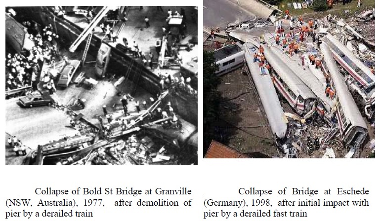
______
______
Derailment management:
In case of rail accidents, the alarm, reconnaissance and rescue will be controlled by the regional traffic control centre (dispatching centre) of the railways or by the nearest station. Should the damage warrant it, the local authorities can take control of the initial intervention (first aid) by co-ordinating the action of the means available (police, fire brigade, civil defence, health services) in close collaboration with the specialist services of the company involved. Subsequently, the rescue plan or red alert for rail disasters can be activated by higher political authorities. Protection, research, rescue and assistance measures will depend upon the intervention tactics dictated by the accident and the means available.
_
Rerailing:
Following a derailment, it is naturally necessary to replace the vehicle on the track. If there is no significant track damage that may be all that is needed. However, when trains in normal running derail at speed, a considerable length of track may be damaged or destroyed; far worse secondary damage may be caused if a bridge is encountered. With simple wagon derailments where the final position is close to the proper track location, it is usually possible to pull the derailed wheelsets back on to the track using rerailing ramps; these are metal blocks designed to fit over the rails and to provide a rising path back to the track. A locomotive is usually used to pull the wagon. If the derailed vehicle is further from the track, or its configuration (such as a high centre of gravity or a very short wheelbase) makes the use of ramps impossible, jacks may be used. In its crudest form, the process involves lifting the vehicle frame and then allowing it to fall off the jack towards the track. This may need to be repeated. A more sophisticated process involves a controlled process using slewing jacks in addition. Photographs of early locomotives often indicate one or more jacks carried on the frame of the locomotive for the purpose, presumed to be a frequent occurrence. When more complex rerailing work is needed, various combinations of cable and pulley systems may be used, or the use of one or more rail-borne cranes to lift a locomotive bodily. In special cases road cranes are used, as these have greater lifting and reach capacity, if road access to the site is feasible. In extreme circumstances, a derailed vehicle in an awkward location may be scrapped and cut up on site, or simply abandoned as non-salvageable.
_
What to do if your train derails:
A train derailment can be an extremely terrifying event, particularly because there is nothing you the passenger can do to prevent one from happening. Derailments occur for a number of reasons including excessive speed, broken/misaligned rails, mechanical failures, engineer problems, etc. If you are a passenger on a train that derails you should follow these steps:
- Stay calm and listen carefully to the announcer on the PA system.
- Look for the closest and safest emergency exit.
- As you exit the train, stay clear of the train tracks.
- Call emergency service or ambulance or police if no one else has done so.
- Maintain a safe distance from the train/subway car.
- If possible, document the scene (take photographs; gather the contact information of witnesses, etc.).
- Go directly to the hospital.
- Keep a journal.
- Conduct an Internet search and print out as many articles about the derailment as possible.
While it is understandable that distressed passengers of derailed trains often prefer to immediately rush to their loved ones or the safety of their own homes, it is important that they instead go directly to the hospital. Train derailments can and often do have a serious impact on the human body. The most common injuries resulting from train derailments are whiplash, back sprains and injury to the spinal column. Failure to seek immediate medical attention not only lead to health complications, but can also have a negative impact on your legal case, as insurance companies will often assume that if you did not go to the hospital right away that you are not hurt. Though it may seem like extra work, the importance of keeping a journal cannot be stressed enough. We all have a mechanism in our brain that suppresses horrific events from our memory bank. It is human nature to forget specific details as time goes by. A journal will help maintain the clarity of the event in your mind.
______
______
Prevention of derailment:
_
Study on derailment prevention strategy:
To gain insights into the potential safety benefits of strategies to reduce various types of derailments, a sensitivity analysis was conducted. Estimation was done to determine by what percentage main track train and car derailment rates would be reduced in the event that certain accident causes were reduced or eliminated. Four of the leading main-line accident causes were considered: broken rails or welds, track geometry defects, bearing failure, and broken wheels. There are a number of approaches in practice or being developed that may address these. Broken rail preventive measures include rail inspection, rail grinding, rail repair, and renewal. Track geometry inspection and maintenance are often based on some measurable indices, such as the track quality index. Wayside and onboard detection systems aim to identify and inform railroads and car owners about the need to remove or repair rolling stock defects before they cause an accident. Hot bearing detectors and wheel impact load detectors are commonly used to detect problems with those components. Nevertheless, these techniques and technologies are not 100% effective in eliminating all the accident causes they are intended to prevent, and research and development are ongoing to further develop their capability.
_
The effectiveness of an accident prevention strategy is defined here as the percentage of the maximum safety benefit it might potentially realize. The sensitivity analysis helps illustrate the relevant potential safety benefit that might be realized if technologies or techniques were implemented with varying degrees of effectiveness. For example, broken rails or welds caused 15.3% of train derailments and 22.7% of cars derailed; thus, if all broken-rail-related causes were eliminated, train and car derailment rates would decline by a corresponding amount. Even if only 50% of broken rails or welds could be prevented, the prevention would result in a larger percentage reduction in train and car derailment rates than would any of the other accident prevention strategies at 100% effectiveness. The effects of different accident prevention strategies may not necessarily be independent of one another. For example, improved wheel condition can reduce dynamic loading of track, thereby reducing track defect rates, and vice versa.
____
Existing preventive measures to reduce Infrastructure caused derailments
- Improved inspection routines: Timely maintenance follow-up of inspection results.
- Upgrade weak infrastructure to match present axle loads: Freight only lines are today used for loading conditions far exceeding their design standard.
- Stricter and more harmonised track geometry requirements to account for international traffic.
- Move signals which may show stop aspect away from track sections with geometry not suitable for low speed braking or acceleration, or adjust track geometry to train operating conditions. Examples: Avoid signals that can show stop aspect behind small radius curves with high cant. Alternatively redesign track geometry or install check rails.
- Greasing of track curves.
- Interlocking of points to avoid operation while occupied by rolling stock: Mainly at stations and shunting yards.
- Increased separation of freight and passenger traffic along different lines and adjustment of track geometry design to most frequent traffic type.
- Apply ‘maintenance free’ superstructure design e.g. fixed track/slab track
____
Existing preventive measures to reduce Rolling stock related derailments
- Measures to avoid Hot Axle Box derailments: Wheel load impact detectors to detect faulty wheels giving excessive vibration to bearing. Improve bearing design by applying more vibration tolerant components in bearing. Track installed detector installations to detect faulty bearings or hot axle boxes. Install Hot axle box detectors and use Bearing acoustic diagnostic.
- Measures to avoid axle shaft fatigue ruptures: Improved design standards.
- Appropriate material selection: Fault free surface corrosion protection.
- Improved in service inspection in order to detect incipient failures.
- Appropriate greasing of bogie pivots and side supports. Apply improved suspension design, e.g.. parabolic blade springs instead of trapezoidal blade springs.
____
Existing preventive measures to reduce Operational related derailments
- Training of operational staff of all types.
- Proper inspection, testing and check of wagons, train prior to departure: Improved tools to ensure quality of these activities, e.g. check lists.
- Improved tools to detect overloading, skew loading and/or insufficient fastened load: Weighing devices at terminal or along track. Visual balances on wagons.
- ATP-system to avoid SPADs and excessive speed across deviated points/turnouts.
_____
Tips to avoid Train Accidents at railway crossings:
The following are tips for commercial drivers to help you avoid an accident with a train or involving train tracks:
- Do not “race” a train to a crossing. Trains move faster than they appear, and if you can see the train, you should wait for it to pass before crossing.
- Never drive around lowered gates, even if there is no train in sight. Driving around lowered gates is illegal and extremely dangerous.
- Make sure your trailer jacks are in the “up” position. Your truck may become stuck on the railroad tracks at crossings if jacks are not retracted.
- If you get stuck on the tracks at a railroad crossing, immediately exit your vehicle and look for the emergency number posted at the crossing. Call this number, or if it’s not available call the police, so that nearby trains are alerted of your position.
- Remember that a train’s stopping distance is even greater than a commercial truck’s. A freight train moving at 55 miles per hour may need up to a mile to stop.
_____
Wheeltapper:
Wheeltapper is a historical railway occupation; people employed to tap train wheels with hammers and listen to the sound made to determine the integrity of the wheel; cracked wheels, like cracked bells, do not sound the same as their intact counterparts. The job was associated with the steam age, but they still operate in some eastern European countries.
____
Guard rails (check rail):
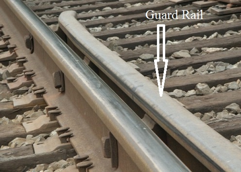
In railroad use, guard rails or check rails are placed parallel to regular running rail along areas of restricted clearance, such as a bridge, trestle, or tunnel. Check rails are also installed to guide the wheels in rigid crossings and point crossings. These have the effect of keeping the wheels of rolling stock in alignment in case of derailment. It also helps to minimize damage to the structure and allow easier post-accident cleanup. On sharp curves, guard rails may be placed inside the inner rail, where they engage the back of the flange of the wheel on that side to prevent lateral movement of wheelset to hinder flange climbing on outer rail in sharp curves. A picture below shows how check rails can be applied in curved line sections.
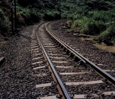
Curved Track in passenger lines with a radius of 200 metres or less should be fitted with a check rail to reduce the risk of derailment.
_
Minimising lateral impact derailment potential at level crossings through guard rails: a 2016 study:
Derailments due to lateral collisions between heavy road vehicles and passenger trains at level crossings (LCs) are serious safety issues. A variety of countermeasures in terms of traffic laws, communication technology and warning devices are used for minimising LC accidents; however, innovative civil infrastructure solution is rare. This paper presents a study of the efficacy of guard rail system (GRS) to minimise the derailment potential of trains laterally collided by heavy road vehicles at LCs. For this purpose, a three-dimensional dynamic model of a passenger train running on a ballasted track fitted with guard rail subject to lateral impact caused by a road truck is formulated. This model is capable of predicting the lateral collision-induced derailments with and without GRS. Based on dynamic simulations, derailment prevention mechanism of the GRS is illustrated. Sensitivities of key parameters of the GRS, such as the flange way width, the installation height and contact friction, to the efficacy of GRS are reported. It is shown that guard rails can enhance derailment safety against lateral impacts at LCs.
_____
Reducing Train Accidents and Derailments through Data Analysis:
In order to cut back on train accidents and derailments, major railway companies are enlisting the help of consulting firms to analyze event recorder data (the railroad equivalent of the “black box”) after incidents occur, conduct preventative evaluations as well as perform testing services. These consulting firms specialize in the application of highly analytical skills to address rail issues and have extensive experience with safety regulations and standards around the world. Additionally, these private consulting firms provide unbiased and factual reports as to what caused accidents or derailments, which can be used to make improvements to the railway infrastructure and prevent future occurrences. Jack Chislett, director of operations analysis, TÜV Rheinland Mobility, Rail Sciences Division has more than 30 years of railroad consulting experience and has extensively used simulations while investigating the cause of rail issues for railway companies. One of Chislett’s latest investigations was to determine how a large freight train became separated, an event known in the industry as a “break-in-two,” upon startup after stopping on a slight ascending grade. The train, made up of three head end locomotives, 7,433 trailing tons and measuring 6,745 feet long, suffered a broken knuckle on the 13th car when it began to throttle-up. With the data pulled from the train’s event recorder data, Chislett used the advanced data analysis and graphing software, Origin, to graph the actual train handling and in-train forces during stop and re-start. From the data, Chislett was able to determine that there was a rapid increase in drawbar force upon the train’s start up. Prior to analyzing the data, it was speculated that the mode of braking and the slightly ascending grade were the possible factors that caused the knuckle failure. Event recorder data confirmed that a combination of dynamic and air-braking was used to stop the train prior to the break-in-two.
_
In order to have a better idea of how to prevent this incident from occurring in the future, the railway company requested a simulation of an alternate case in which locomotives were kept under light throttle during the stop, while braking was accomplished by train air-brakes only. The data showed that under these conditions, the train would have come to rest in a lightly stretched state. In contrast, Chislett’s simulations of the actual case in which the train was stopped using a combination of dynamic and air-braking, showed the train coming to rest in a bunched, compounded state. In this bunched state, the release of the brakes just prior to throttle-up resulted in each car rolling backwards just as the locomotives were applying force in the opposite direction. This action amplified the forces being applied to each car and led to the failure of the knuckle on the 13th head car. In the simulations of an alternate braking case wherein the locomotives were kept in light throttle while only train air-brakes were applied, produced a lightly stretched train and subsequently, a much lower and more static force distribution at the drawbar, across all cars. The ability to use graphing and data analysis software in investigative work has enabled railroad consultant experts to see what measures could have been taken to prevent accidents and/or derailments.
_____
Linke Hofmann Busch (LHB) coaches:
There is lack of sufficient ‘Safety Features’ in 80% of railway coaches in Indian railway. These coaches are products of the Integral Coach Factory (ICF) – one that produces the outmoded varieties. The factory is located in the vicinity of Perambur, close to Chennai and happens to be one of the leading coach production factories. These coaches are made using mild steel, which in spite of being heavier than stainless steel is still incapable of saving passengers during collisions. Linke Holfmann Bush coaches are designed not to topple or climb over each other on derailment, and would have considerably reduced the number of causalities after derailment. Linke Hofmann Busch (LHB) coaches are the passenger compartments of Indian Railways that have been developed by Linke-Hofmann-Busch of Germany (renamed Alstom LHB GmbH in 1998 after the takeover by Alstom) and produced by Rail Coach Factory in Kapurthala, India. Initially, 24 air conditioned coaches were imported from Germany for use in the Shatabdi Expresses, after which the Rail Coach Factory started manufacturing after technology transfer. The coaches are designed for an operating speed up to 160 km/h and could go up to 200 km/h. They are considered to be “anti-telescopic”, which means they do not get turned over or flip in case of a collision (chiefly head-on). These coaches are made of stainless steel and the interiors are made of aluminium which make them lighter as compared to conventional rakes. Each coach also has an “advanced pneumatic disc brake system” for efficient braking at higher speeds.
_____
_____
Rail inspection:
Rail inspection is the practice of examining rail tracks for flaws that could lead to catastrophic failures. In order for a railroad to function effectively all aspects of the system should be maintained in good working order. Locomotives and rolling stock regularly move through areas where they can be inspected and maintained. However track does not move, so inspectors must traverse the line either on foot or in a rail mounted vehicle and maintenance crews must be sent to specific locations to make track repairs, which may not always happen before a service disruption. A track failure, due to either exceeding some industry or governmental specification or an acute failure, such as a rail break, can result in costly delays or even derailments with significant consequences. To help avoid such failures, it is beneficial for a railroad to be able to predict when and where failures might occur and then evaluate the relative costs and benefits of performing maintenance activities to ensure that the most cost effective actions are taken.
_
According to the United States Federal Railroad Administration Office of Safety Analysis, track defects are the second leading cause of accidents on railways in the United States. The leading cause of railway accidents is attributed to human error. The contribution of poor management decisions to rail accidents caused by infrequent or inadequate rail inspection is significant. The single most important asset to the heavy haul industry is its rail. However, the primary concern of the railroad companies is the probability of rail flaw development, and broken rails, resulting from the repeated applications of high-contact stress from the heavy axle loads that are encountered today. This has resulted in the railroad companies improving their maintenance practices and increasing their test methods and frequencies. One of the most important practices for the reduction of broken rail is the nondestructive inspection process. This includes several technologies and methods that are in use in the heavy haul industry today with the objective of obtaining full life potential of the rail section. These technologies and methods must be capable of performing an accurate, reliable, and effective test in an ever-changing environment while at an acceptable speed that will not interfere with the service functionality of the railroad. Every year, North American railroads spend millions of dollars to inspect the rails for internal and external flaws. Nondestructive testing (NDT) methods are used as a preventative measures against track failures and possible derailment. The North American railroads have been inspecting their most costly infrastructure asset, the rail, since the late 1920’s. With increased traffic at higher speed, and with heavier axle loads in the 1990’s, rail inspection is more important today than it has ever been. Although the focus of the inspection seems like a fairly well-defined piece of steel, the testing variables present are significant and make the inspection process challenging. Rail is manufactured in different weights; there are different rail conditions (wear, corrosion etc.) present; there are a significant number of potential defects possible; and the task has to be performed with some speed to reliably inspect the thousands of miles of track stretching across the land. The heavy loads and high speed of today’s trains can cause rails to fail in service unless regular inspections are performed.
NDT methods for rail inspection and flaw detection:
A list of methods used to detect flaws in rails:
- Ultrasound – the most popular method
- Eddy current inspection – great for surface flaws & near surface flaws
- Magnetic Particle Inspection (MPI) – used for detailed manual inspection
- Radiography – used on specific locations (often predetermined) such as bolt holes and where thermite welding was used
- Magnetic induction or Magnetic flux leakage – earliest method used to locate unseen flaws in the railway industry
- EMAT Electromagnetic Acoustic Transducer
The techniques mentioned above are utilized in a handful of different ways. The probes and transducers can be utilized on a “walking stick”, on a hand pushed trolley, or in a hand held setup. These devices are used when small sections of track are to be inspected or when a precise location is desired. Many times these detail oriented inspection devices follow up on indications made by a rail inspection cars or HiRail trucks. Handheld inspection devices are very useful for this when the track is used heavily, because they can be removed relatively easy. However, they are considered very slow and tedious, when there are thousands of miles of track that need inspection.
_
Visual inspection:
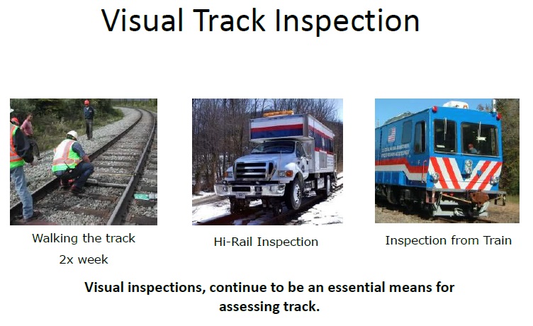
Rail inspections were initially performed solely by visual means. Of course, visual inspections will only detect external defects and sometimes the subtle signs of large internal problems. The patrol man, Permanent Way Inspectors and other staff constantly monitor the tracks physically at regular intervals in India. The need for a better inspection method became a high priority because of a derailment at Manchester, NY in 1911, in which 29 people were killed and 60 seriously injured. In the U.S. Bureau of Safety’s (now the National Transportation Safety Board) investigation of the accident, a broken rail was determined to be the cause of the derailment. The bureau established that the rail failure was caused by a defect that was entirely internal and probably could not have been detected by visual means. The defect was called a transverse fissure as shown in the figure below. The railroads began investigating the prevalence of this defect and found transverse fissures were widespread.
![]()
_
Induction method (Magnetic induction or Magnetic flux leakage method):
In 1915, the Bureau of Standards began research to determine if magnetic testing could be used to detect transverse fissures. The basis for induction testing requires the introduction of a high-level direct current into the rail head, establishing a magnetic field around the rail head. In the induction test process, the magnetic field is considered a region consisting of concentric lines of force perpendicular to the rail head. Once the magnetic field is established, it will remain constant in strength and shape as long as the rail weight, rail head contour, and current flow remain constant. The current is generally around 1200A to 3600A; however, it can vary by rail weight and test speed. The introduction of the current is applied by using two sets of electrodes that are placed on the rail head. The spacing between the electrode sets is approximately 120 cm and the current flows into the rail from the forward electrode set and out through the trailing electrode set. During this process, the rail head becomes an electrical circuit that flows longitudinally through the rail head. The induction sensor unit is then passed through the magnetic field. The unit containing the induction sensors is located between the two sets of brushes at a pre-set distance above the surface of the rail head. This clearance must be maintained throughout the continuity of the test to ensure test integrity. When motion is introduced, the sensor unit moves through the magnetic field and it detects a distortion in the concentric lines of force in the established magnetic field where an electromotive force is induced. This electromotive force is measurable as a voltage. If the sensor unit is passed through the magnetic field and there is no distortion, then no electromotive force is measured. In modern rail weights, only the head and the top part of the web are “saturated” with current. As the current flows through the rail, any condition, such as a defect, will distort the current path. The distortion of the current flow will also lead to a distortion of the associated magnetic field. It is this distortion of the magnetic field that is detected by the search unit. The search unit houses multiple sensors aligned in various planes in relation to the rail head. Multiple sensors, arranged in various planes in relation to the rail head, are used to allow the detection of all the components of the magnetic field disturbances. The signals received by the sensor unit are sent to the test system and evaluated to determine if they meet or exceed a set threshold. If the signals exceed the predetermined threshold level, the data is presented to the operator for interpretation as a potential defect. The processed data is then kept as the permanent record of test. Computers are now being used to record and evaluate the defect. It is very important that the system is able to saturate the rail head with electrical current, or the quality of the test can be jeopardized.
_
Unfortunately, transverse fissures are not the only types of defects found in rail. Other manufacturing and service-related defects that can occur include inclusions, seams, shelling, and corrosion. Fatigue cracks can initiate from these defects, as well as normal features of the rail such as bolt-holes. If these defects go undetected, they can lead to rail head and web separations. Many of these defects are not detectable with the flux leakage method because the flaws run parallel to the magnet flux lines or the flaws are too far away from the sensing coils to detect. The induction technique inspects mainly the railhead.
_
Ultrasonic inspection:
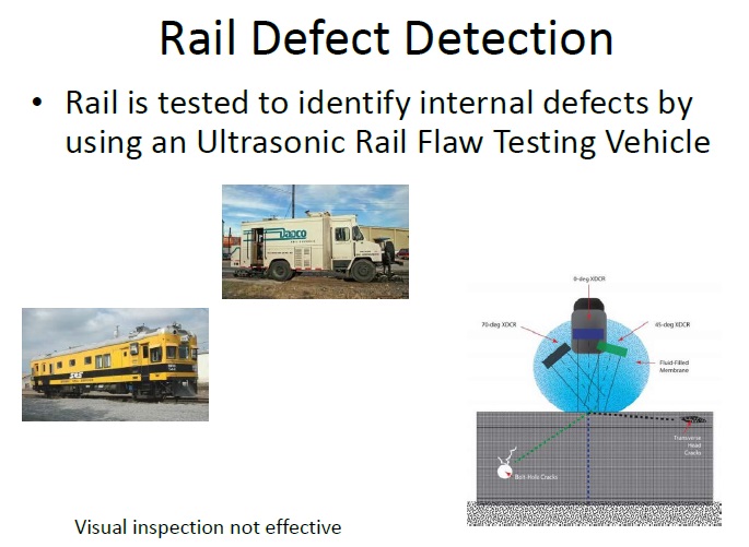
_
To complement the flux leakage method, and detect additional flaw types, ultrasonic inspection has become common. High-frequency sound is transmitted into the metal rail and reflections from rail joints and surface conditions, as well as internal defects, are displayed on a screen or cause movement of a pen on a recording tape. Both normal- and angle-beam techniques are used, as are both pulse-echo and pitch-catch techniques. The different transducer arrangements offer different inspection capabilities. Manual contact testing is done to evaluate small sections of rail but the ultrasonic inspection has been automated to allow inspection of large amounts of rail, like the electromagnetic technique previously discussed. The first all-ultrasonic inspection car was introduced in 1959. This car was developed specifically to meet the needs of the New York City Transit Authority (NYCTA). Fluid filled wheels or sleds are often used to couple the transducers to the rail. These Roller Search Units (RSU’s) comprise of combination of different transducer angles to achieve the best inspection possible.
A schematic of an RSU is shown below.
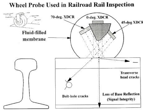
_
Ultrasonics are briefly described as sound waves that are propagating at a frequency that is above the range of human hearing, normally above a range of 20,000 Hz or cycles per second. The range normally used during current flaw detection operations is 2.25 MHz (million cycles per second) to 5.0 MHz to measure geometric and physical properties in materials i.e. rails. Ultrasound travels in different materials at different speeds (velocity). However, the speed of sound propagation in a given material is a constant. There are several ways that sound travels through a material. One type of sound wave, called longitudinal or compression travels about 330 metres per second in air and about 6400 metres per second in aluminium or in steel at approximately 5960 metres per second. To perform ultrasonics, electrical energy is converted to mechanical energy, in the form of sound waves, by a transducer. The transducer accomplishes this energy conversion due to a phenomenon referred to as the piezoelectric effect. This occurs in several materials, both naturally-occurring and man-made. Quartz is a naturally occurring piezoelectric material. A piezoelectric material will produce a mechanical change in dimension when excited with an electronic pulse. Similarly, this same material will also produce an electric pulse when acted upon mechanically.
The ultrasonic test method of rail testing is described briefly as follows:
- Ultrasound is generated onto the rail at various angles by piezoelectric transducers that are manufactured from ceramic materials. The transducers are contained in a wheel assembly, or sled device, which rides on top of the rail head. The ultrasound is produced by applying a voltage to the transducer itself.
- The wheel/sled containing the transducers is commonly referred to as the search unit.
- The transducers are positioned at several different angles. The ultrasound produced by these transducers normally covers the rail from the top of the rail head through the web to bottom of rail and the entire width of the rail head. The base portion off center of the rail is currently not covered by current test systems.
- Ultrasound is generated into the rail at all angles associated with the system at test speeds up to 100 km/h.
- If a condition is encountered of sufficient size and orientation that would offer a reflector to the ultrasound that is transferred into the rail, the ultrasound is then reflected back to the respective transducer. These conditions would include rail head surface conditions, internal or visible rail flaws, weld upset/finish, or known reflectors within the rail geometry such as drillings or rail ends.
- The information reflected back to the transducer is then processed by the test system and is recorded in the permanent test data on the coinciding display for that ultrasonic channel.
In effect, the ultrasound produced from the transducer travels through the rail specimen from the top of rail head. If the sound path is uninterrupted, no reflected signal is returned to the transducer. If a condition exists, such as a rail head surface irregularity, rail geometry reflector (bolt hole drilling, weld upset/finish, rail end, etc.), or internal rail flaw, the ultrasound produced will reflect back to the transducer and an equipment response is presented to the operator for interpretation. The information processed by the test system is maintained on a permanent record of test. Test systems that are used by heavy haul lines normally use a minimum of 24 ultrasonic test channels, 12 on each rail. However, recently systems that can accommodate more than 24 channels and additional wheel/sled angled test probes have been developed.
_
Limitations of ultrasonic flaw detection of rails:
- Surface must be accessible to transmit ultrasound.
- Skill and training is more extensive than with some other methods.
- It normally requires a coupling medium to promote the transfer of sound energy into the test specimen.
- Cast iron and other coarse grained materials are difficult to inspect due to low sound transmission and high signal noise.
- Linear defects oriented parallel to the sound beam may go undetected. To detect the defect efficiently, ultrasonic beam is to be directed towards the flaw perpendicularly, otherwise, the reflected beam may not be received by the receiver crystal, resulting in absence/reduction in amplitude of flaw signal in the CRT. Ultrasonic flaw detection devices available in the inventory of the Indian Railways are capable of “vertical verification” and can detect cracks or rail fractures along the vertical length of tracks, but cannot undertake “horizontal checks”.
- Reference standards are required for both equipment calibration and the characterization of flaws.
- The ultrasonic probes used in the rail testers have a frequency of 4MHz (longitudinal wave) and 2MHz (transverse waves). Therefore, cracks lesser than 0.8mm size cannot be detected by the present arrangement.
- Rails having rust, pitting, hogging, battering of rail end, misalignment of joints, scabs, wheel burns and other surface imperfections restrict proper acoustic coupling between probe and rail table and may not permit detection of flaws. Whenever such defects are encountered, loss of back wall echo or an alarm signal is obtained. This indicates that defects if any below these patches may remain undetected. Under such circumstances hand probing may be done.
- Ultrasonic inspection of rails is usually restricted to low speeds of around 20-30mph, which limits the viability of testing many tracks regularly. Higher speed inspection has been reported of up to 60mph, but no indication of the change in reliability is quoted for these speeds.
- The wheel probe is configured so that it generates either compression or shear waves in the rail, and one issue with surface defects is that a small defect can obscure the detection of a deeper defect, and as such defects often occur in clusters this is clearly a potential reliability issue.
_
New Ultrasonic Technology could help prevent Train Derailments:
A team led by UCSD structural engineering professor Francesco Lanza di Scalea describes a defect-detection technique that uses laser beam pulses to gently “tap” on steel rails. Each laser tap sends ultrasonic waves traveling 1,800 miles per second along the steel rails. Downward facing microphones are positioned a few inches above the rail and 12 inches from the downward pointed laser beam. As the prototype vehicle rolls down the test track delivering laser beams taps at one-foot intervals, the microphones detect any tell-tale reductions in the strength of the ultrasonic signals, pinpointing surface cuts, internal cracks, and other defects. Some of the worst derailments have occurred on tracks recently inspected by the current generation of technology, which often doesn’t detect interior cracks in rails that happen to lie under areas of superficial cracking. This technique is much better able to find such defects, and it can work under varying weather conditions while the inspection vehicle is zipping along a track at speeds of up to 70 mph.
_
Summary of NDT technologies for detecting rail defects:
| NDT Technique | Systems Available | Defects Detected | Performance |
| Ultrasonics | Manual and high-speed systems (up to ~70 km/h) | Surface defects, rail head internal defects, rail web and base defects | Reliable manual inspection but can miss rail foot defects. At high speed can miss surface defects smaller <4mm as well as internal defects, particularly at the rail base. |
| Magnetic Flux Leakage | High-speed systems (up to 35 km/h) | Surface defects and near surface internal rail head defects | Reliable in detecting surface defects and shallow internal rail head defects although cannot detect cracks smaller than <4 mm. MFL performance deteriorates at high speeds. |
| Pulsed Eddy Current (including Field Gradient Imaging) | Manual and high-speed systems (up to 70 km/h) | Surface and near-surface internal defects | Reliable in detecting surface breaking defects. Adversely affected by grinding marks and lift-off variations. |
| Automated Visual Inspection | Manual and high-speed systems (up to 320 km/h) | Surface breaking defects, rail head profile, corrugation, missing parts | Reliable in detecting corrugation, rail head profile missing parts and defective ballast at high speeds. Cannot reliably detect surface breaking defects at speeds > 4 km/h. Cannot assess the rail for internal defects. |
| Radiography | Manual systems for static tests | Welds and known defects | Reliable in detecting internal defects in welds difficult to inspect by other means. Can miss certain transverse defects. |
| Electromagnetic Acoustic Transducers | Low speed hi-rail vehicle (<10 km/h) | Surface defects, rail head, web and base internal defects | Reliable for surface and internal defects. Can miss rail base defects. Adversely affected by lift-off variations. |
| Long Range Ultrasonics | Manual systems and low-speed hi-rail vehicle systems (<10 km/h) | Surface defects, rail head internal defects, rail web and base defects | Reliable in detecting large transverse defects (>5% of the overall cross-section). |
| Laser Ultrasonics | Manual and low-speed hi-rail vehicle systems (<15 km/h) | Rail head, web and base defects | Reliable in detecting internal defects. Can be affected by lift-off variations of the sensors, difficult to deploy at high speeds. |
| Alternating Current Field (ACF) Measurements | Manual systems (hi-speed system under development) | Surface breaking defects | Reliable in detecting and quantifying surface breaking defects. Cannot detect sub-surface defects. Very good tolerance to lift-off variations. |
| Multifrequency Eddy Current Sensors | Manual system, static and slow speed | Surface and near surface defects | Limited experiments conducted. Has potential to reliably quantify defects detected. |
_____
_____
Rail inspection cars:
Rail inspection cars and HiRail trucks are the answer to today’s high mileage inspection needs. These rail inspection cars are basically their own train with inspection equipment on board. The probes and transducers are mounted on carriages located underneath the inspection car. Modern day inspection cars now use multiple NDT methods. Induction and ultrasound methods can be used in rail inspection cars and operate at testing speeds of more than 30 mph (48 km/h). The next generation will go even faster. There are many manufacturers of road/rail inspection trucks, otherwise known as HiRail trucks. These HiRail inspection cars are almost all ultrasonic testing exclusively, but there are some with the capability to perform multiple tests. These trucks are loaded with high speed computers using advanced programs which recognize patterns and contain classification information. The trucks are also equipped with storage space, tool cabinets, and workbenches. A GPS unit is used with the computer to mark new defects and locate previously marked defects. The detector car will test rail between 6.5 and 13 miles per hour. However, higher speed units are in development. The data from the inspection equipment is fed to the operator inside the car. The Federal Railroad Administration (FRA) requires that any indications of defects need to be hand verified immediately. This leads to a stop-start test mode. When the operator sees something on the tape indicating a problem, he uses a buzzer signal system to tell the driver up front to stop. The car then backs up to the point of examination where the operator gets out to hand test the rail with an ultrasonic test set mounted on the rear of the car. If a defect is confirmed, it is marked and a railroad work crew following the test car will change the rail. If they can’t get to it right away, the section of track is assigned a slow order (slower speed) until the crew can repair it. The amount of rail being tested can be increased by the use of chase cars following the testing vehicles. The chase cars will receive a radioed signal of the test being done by the lead truck and will stop to do the necessary hand testing. This elimination of the need to back up to hand test, allows the testing vehicle to move forward, continuously testing, with the results being sent and recorded for examination by the chase car. The GPS system allows a chase car to find precisely where the flaw was detected by the lead vehicle. One advantage to the HiRail trucks is that they can work around regular rail traffic without shutting down or slowing down entire stretches of track. However, because railroad management frequently orders HiRail trucks to be used to inspect tracks at speeds over 50 mph (80 km/h), tracks reported as having been inspected are, in fact, not inspected. A NTSB report on the Amtrak derailment in Oregon in 2006 documented this fact.
_
Continuous Test Process:
The continuous test process consists of operating a high-speed vehicle-based test system nonstop along a designated route, sometimes covering in excess of 150– 300 km per shift. The test data is then analyzed according to defined standards at a centralized location. Once analyzed, reports are sent out to a verification staff via the Internet. They verify “suspects” to confirm as “defects” using a portable test unit or a portable hand-held flaw detector. Verification reports are transmitted back to the railroad over the Internet for records and proper remedial action. This process also produces a permanent record of test for future analysis.
_
Automated Railway Inspection System can help prevent Train Accidents:
A team of researchers from UMass Lowell, Duke University, the University of Vermont, the University of Alaska, Fairbanks and Penn State Altoona has recently received a two-year award of $1 million from the U.S. Department of Transportation’s Research and Innovative Technology Administration (RITA) to develop a high-tech automated system for inspecting and monitoring the health of the country’s rail transit infrastructure. Keeping better tabs of railroad tracks, bridges and tunnels could help prevent passenger trains from derailing. This system will use ground-penetrating radar, laser, geographic information system and GPS to automatically check and collect surface and subsurface data on the track’s steel rails, concrete ties, fastening systems and ballast. The special algorithms and software tools will analyze and interpret the data and assist in detecting and locating rail defects and safety hazards, such as broken ties, missing bolts, fouled ballast and wide rail gauge. In addition, a WebGIS-based decision support system will be developed to help visualize the inspection results. This will make it very easy for railroad track owners and operators to identify where the problems are and how severe they are.
_
The future of rail inspection:
With increased rail traffic carrying heavier loads at higher speeds, a quicker more efficient way of inspecting railways is needed. Lasers inspect railway geometry, and one day they might be utilized as a form of non-contact evaluation of the rail. This most likely will be done with laser-optical transmitting transducers in ultrasonic testing. Eliminating contact with the rail could one day allow high speed detection of flaws. (Testing of rail is currently able to be done at 80 km per hour with a Speno US-6 Ultrasonics train) Another need for the future is a complete rail inspection system. A step in this direction is deeper investigation of the rail by using low frequency eddy currents. Other advancements could include neural network analysis of signals to improve defect detection and identification and longitudinal guided ultrasonics. Improved rail quality, composition, and joining techniques could lead to better wear characteristics and a longer lifespan of the rail. Some investigation into bainitic steels looks promising. A safe and portable means of filmless radiography could assist with onsite defect evaluation. These are just a few advancements in the process of being developed for future use.
______
______
Better management of wheel-rail interaction to prevent derailment:
A key part of reducing railroad costs and improving safety is through better management of wheel and rail profiles to extend life, reduce vehicle and track maintenance, and improve vehicle stability. The increased energy dissipated at the wheel-rail interaction from wheel/rail profile mismatch and the friction/wear directly affects the fuel required to haul a train. Many wheel-rail interface research studies were carried out. The wear and fatigue life of wheel-rail interactions depend greatly on properties such as contact stress, surface hardness, and compressive residual stress, which in turn are controlled by the wheel-rail microstructure and the way they interact. This interaction also affects fuel consumption, derailment risk, and vehicle stability. Most of the damage on the rail is caused by rolling contact wear (RCW) and rolling contact fatigue (RCF) since train wheels and rails are always in contact with dynamic motion in addition to environmental influences. Once the rail surface is damaged, the wheel-rail profile is mismatched and wear is accelerated by friction. The rail surface condition becomes worse to cause failure at the weak points. Before the micro-cracks initiated at the weak points grow over the designed threshold criteria, the rail surface should be inspected and repaired.
_
There have been many studies on rail damage and maintenance in order to secure safety on the railway. The wear resistance of the rail-wheel interface was studied earlier using a tin disk testing method, which is a simple way to evaluate the wear characteristics of material. It has been also reported earlier that the wear rate of the rail-wheel interface can be reduced with an increase in hardness. In addition to the wear behavior, the fatigue strength of rail materials has been studied by many scholars. For example, Brunel et al. investigated the fatigue behavior of railway steels including steel grade and sliding condition effects by using a rolling contact fatigue testing machine. They concluded that the classification of the material grades and sliding conditions can be selected by the RCF test method. Moreover, surface and heat treatment methods can improve the wear and fatigue behaviors of the rail-wheel interface. The wear behavior of bainitic rail-wheel steels was investigated using a wear tester under reciprocating dry sliding conditions by Sharma et al. They found that the bainitic steels exhibited a better wear resistance compared to the existing pearlitic and ferritic-pearlitic steels due to the presence of a typical bainitic morphology. Also, the influence of laser dispersed treatment (LDT) on RCW and RCF behaviors of railway wheel steel was investigated by Zeng et al. It was found that the LDT effectively improved both the wear resistance and RCF behavior of the railway wheel steel due to the formed fine martensite and retained austenite.
_
The surface of the rail head is open to foreign objects, vibration, slip, friction and stress. Thus, the rail surface is hardened by heat treatment at the critical sites. The heat treatment of the rail head is often applied to strengthen the surface of the rail in use under severe conditions, but there is still ongoing demand to increase the wear resistance and rolling contact fatigue strength. Moreover, the friction and wear behavior is central to understanding and optimizing the wheel-rail interaction due to the vehicle dynamics and traction at braking. Also, deformation generated under contact stress may lead to surface and sub-surface shear stresses that increase rolling resistance and, more importantly, contribute to decreased wear resistance and deteriorated fatigue. No ideal material that does not wear and or suffer from fatigue for railway and wheel applications has been found yet. Therefore, there is a need to increase the mechanical properties of both rails and wheels in order to improve the wear and to extend the fatigue life. Molyneux-Berry et al. investigated the effects of wheel-rail contact conditions on the microstructure and hardness of railway wheels. They concluded that the microstructure and hardness have a significant influence on the wheel-rail contact conditions. Wang et al. also reported on the friction, wear and surface damage behavior of rails and wheels with different hardnesses. It was found that the hardness of the wheel had no effect on the rolling friction coefficient of the wheel-rail interaction, but the wear volume decreased with increasing the hardness of the wheel. Hence, it can be concluded that the surface hardness and microstructure play an important role in determining the friction, wear and surface damage of rail-wheel interactions.
_______
_______
Countermeasures to prevent derailment on curve:
- The most effective prevention method for the train overturning is the prohibition of over-speed curving by signalling systems.
- In USA, NTSB declared the necessity of equipment of PTC (Positive Train Control) system, which is the advanced train control system including the prevention of excessive speed running.
- The second most important factor besides overspeeding is the center of gravity (C.G.) height of vehicles. The ratio of C.G height to gauge width deeply influences the critical overturn speed. High C.G center height is an obvious disadvantage against overturn. The designing of lower C.G height vehicles is desired considering passengers’ weight.
- Train drivers’ education and training are also necessary and important. It is important for train drivers to learn the speed limit of curving of the train by schooling.
- Prevention of wear and fatigue of wheel-rail interface and flanges
- Installation of check rails at sharp curves (vide supra)
______
______
Derailer:
A number of other mechanisms exist to protect the line. Traditional ones are catch points (where you have points to direct a train away from other lines that may be occupied, typically with some short section of track beyond) and derailers (designed to immediately derail a train, primarily used around places like depots where movement speeds are low). In this case, the train passed over catch points which were set to protect the mainline. While derailing a train causes disruption, had it run into a busy commuter train the outcome could’ve been a disaster. A derail or derailer is a device used to prevent fouling of a rail track (or collision with anything present on the track, such as a person, a train or a fallen branch) by unauthorized movements of trains or unattended rolling stock. The device works by derailing the equipment as it rolls over or through it. Although accidental derailment is damaging to equipment and track, and requires considerable time and expense to remedy, derails are used in situations where there is a risk of greater damage to equipment, injury or death if equipment is allowed to proceed past the derail point.
Derails may be applied:
- where sidings meet main lines or other through tracks
- at junctions or other crossings to protect the interlocking against unauthorized movement
- temporarily at an area where crews are working on a rail line
- approaching a drawbridge, dead end, or similar hazard.
Derails have failed on occasion, such as the Newark Bay rail accident of 1958, or on April 1, 1987, at Burnham, Illinois, when an unsecured car in a siding defeated a derail and fouled the mainline. Due to rusty rails, the car then failed to shunt the track circuit that should have put block signals to “stop”.
_______
_______
Installation of detectors and sensors:
Detectors/sensors could be on the track and/or the train.
_
Derailment and Dragging Object Detectors:
Derailment and dragging object detectors can be installed to identify if a train has a derailed axle, or equipment that has come loose from a wagon and being dragged along the track between the rails. Such detectors may be installed in front of large stations or structures where the situation may cause major damage. They are extensively used in the US. Early dragging equipment detectors were of the “brittle bar” type. Fixed elements between and beside the rails would break when struck by foreign objects. Their breakage would interrupt an electric circuit that formed part of the reporting system, and the train would be stopped and inspected. The introduction of “self-restoring” dragging equipment detectors, which are hinged and sprung so they return to position after impact, have reduced maintenance requirements for such installations. Figure below shows a typical derailment and dragging object used in the US. If employed in Europe one has to modify the design to avoid being hit by hanging screw couplers. The derailment and dragging object detectors will also detect derailments and are also included as a mitigating measure.
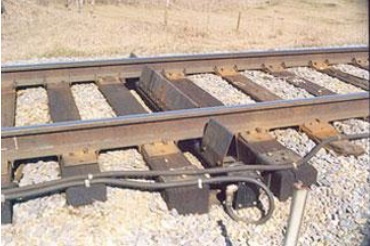
_
Bogie Steering Performance Detectors/Lateral Instability Detection (bogie hunting):
This wayside defect detection system is capable of detecting and identifying train bogies that exhibit poor performance. This system monitors safety performance in several regimes such as: potential of flange climb derailment, gauge spreading, and rail over. This state-of the-art system has the capability to benchmark bogie performance on a fleet-wide basis. They are used in the US and at least in Turkey.
_
Wheel impact load detector (WILD):
Execs at MTA Metro-North Railroad are working to minimize the risk of a derailment caused by a track or wheel defect, too. The detectors, which use sensors applied to track to measure the stress induced by a passing wheel, are more commonly used by freight railroads in areas involving heavy axle loads. In those cases, a wheel defect could lead to rail fatigue and damage running rail. In the commuter-rail environment, a flat wheel wouldn’t necessarily cause damage to the track since trains aren’t carrying the heavy cargo that freight trains do. Rather, the wheels could damage the vehicle itself. For example, in 2009, a flat wheel caused a fatigue fracture in the axle of a Metro-North rail car, causing the wheel to fall off. Shortly after the incident, the railroad installed WILD systems on four tracks in the Park Avenue Tunnel leading toward Grand Central Terminal, which all Metro-North trains enter each day. The system monitors all 1,050 pieces of Metro-North rolling stock, which equates to 8,400 wheels. It’s easy to generate a wheel defect on any given day, and it’s hard to expect human beings to check these wheels with a high degree of accuracy every single day.
_
Derailment Detector:
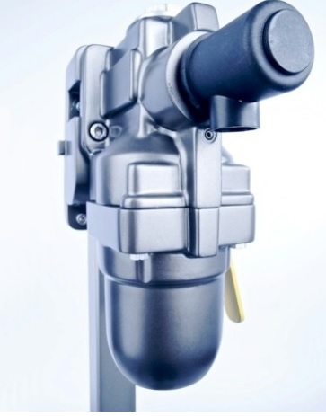
The EDT101 consists of an emergency brake valve, a mounted spring-mass valve and an indicator device. In the case of derailment, the increase in vertical acceleration is registered by the spring-mass valve. This immediately activates the emergency brake valve, which opens the main brake pipe and releases the emergency brake. The main brake pipe is almost entirely vented. The EDT101 then independently returns to its operating state and a red cylinder on the indicator device shows which unit has reacted. The cylinder can be easily manually reset. The unit can be deactivated manually at any time. The purpose of a derailment detector is to stop the train by activating automatic application of the brake when its triggering threshold has been reached after the occurrence of a wagon derailment. This derailment detector cannot prevent derailments.
Applications:
- Freight cars
- Tank cars
- Transport of dangerous goods
Benefits:
- Increased safety for goods wagons, persons and environment
- Reduces consequential damage of derailments
- Issue of an immediate braking if an axle becomes derailed
- Simple retro-fitting to existing wagons
- Low running costs
- Easy upgrading
- High reliability
- Self-contained wagon system
- Good cost-benefit ratio
- UIC approved
- No false activation experienced
_
IIT Kanpur is developing a number of technologies for improving the safety of rail journeys. The derailment detectors are fitted on the end of a coach or wagon of premier trains in India, and are designed to immediately apply brakes in the event of such unusually high level of vibrations. The action time in detector system is much faster than the reaction time taken by the driver or the guard to sense that a coach or wagon has derailed. The device can, therefore, immediately apply brakes and save further consequential damages since the train would come to a halt much faster. Passenger coaches or wagons often tumble and overturn in the event of derailment which causes loss of lives and severe damages to coaches.
__
Broken Rail Detector:
NGRT Broken Rail Detection (BRD) is a system designed to detect cracks in the rails, complete rail separation and also any anomalies within the rail profile that could contribute to a risk of rail failure. A NGRT Main Assembly with 4 Vibration Detection Unit’s per track is installed with a typical separation distance of five kilometers. After detecting anomalies and evaluating the type of anomaly, a warning is sent to the specific and identified customers’ recipient, be it the train operational center and control, Track Engineers or the maintenance team.
__
Linear sensor:
How to prevent train derailment by utilising linear sensors:
Bridge expansion and contraction due to seasonal heating and cooling is a common problem found in civil engineering. Engineers typically place expansion joints in bridges to counter the effects of expansion and contraction due to seasonal heating and cooling. However, when it comes to railway bridges, this problem is compounded as the expansion of a mile-long section of rail could be as much as 1.5m over a temperature change in some climates of 37.7°C, leading to rail buckling, or ‘sun kink’, and resulting in train derailments. The LV-45 series linear sensors from Bestech Australia are being used to measure bridge movements. Designed to survive elements such as high humidity, blowing snow, and driving rain over a wide temperature range (-40°C to 100°C), as well as withstand the inherent shocks and vibration from a train, the Alliance Sensors LV-45 series is the ideal solution for such applications. In a typical pier-to-bridge interface measurement application, the LV-45 sensors are hard fixed to the pier and the bridge, using ball joint swivel rod-ends to take up any misalignment during initial installation. The system can measure position changes in all three axes and track those changes over time to show short and long term trends and highlight potential problems or incipient failures before they take place Alliance Sensors Group’s LV-45 series linear sensors is being used in the Metrom Rail LLC SafeStructure System for road and rail bridge monitoring to help prevent train derailment. Advancements in steel tracks including the use of pre-stressing techniques are helping to control the effects of expansion and contraction. Many railway companies and mass transit agencies are taking the solution a step further by instrumenting the bridges themselves to find out the extent of movement of the bridge, and to determine if any structural problems exist or if any track shifting has actually taken place. By knowing that tracks have buckled or kinked, railway companies can divert trains and repair track problems before a potential incident.
__
Vibration sensor:
Anyone who’s lived close to railway sidings and goods yards will be familiar with the terrible squeal of metal wheel flanges against the heavily worn inner surfaces of curved track. At low speeds, such rail squeal represents little more than an annoyance but at increased speed and train weight, it could be the prelude to a major derailment. Mounted onto the train’s bogies, the sensors detect levels of vibration beyond those that would be normally expected and which would indicate friction between the wheel flanges and the inner radius of the rail. As vibration levels increase, the risk of the wheel “climbing” the rail and dismounting becomes larger. Excessive vibration leads to automatic train braking and the detection of a curve determines how much lubricant should be delivered to the wheel flange. The Spanish built AVE Class 102 and Talgo coaches will be protected by curve detection and vibration sensors supplied by German company, Micro-Epsilon as they hurtle across the 453km (281 mile) stretch of track in Saudi Arabia at speeds approaching 300kph (186mph). The IP68 and EN50155 rated, stainless steel mounted vibration sensors are mounted on the train’s Bombardier wheel-sets and interact with the two innovative gyroscopic curve detectors which are mounted fore and aft on the train. The front sensor detects when the train moves into a curve and the rear sensor detects when the train moves out of the curve. The wheel lubrication system is activated on and off by these two sensors, providing lubricant to the wheels precisely when (and in the volume) it is needed. The gyroscope measures the angular velocity of the train on a continuous basis and provides a current and voltage output to the train’s central electronic control or onboard telemetry system. As vibration increases and the curve tightens, more lubricant is delivered to the interface between the wheel flange and the rail. Delivering exactly the right amount of lubricant not only reduces the likelihood of derailment, but also improves comfort, reduces noise levels and lessens the amount of wear on the rails and wheels whilst optimising lubricant costs. A combination of gyroscopic curve detection and vibration measurement ensures enough wheel lubricant is supplied to prevent high speed trains from derailing on curves. In addition, the sensor can be used for collecting data for predictive maintenance of the wheels, which increases maintenance intervals and train availability.
__
Cracked wheel detection sensor:
Broken wheels are a major cause of derailments. Now high-tech sensors can take ultrasound pictures of the wheels in a millisecond, capturing microscopic cracks that can cause a catastrophe.
__
Hot Axle and Box Detector:
Before there is a derailment, the stress on the wheels overheat them. This is just before the wheels seize up and stop functioning, leading to derailment or track damage. Hot Axle and Box Detection (HABD) systems are used the world over for monitoring the possibility of derailment in real time. The technology takes rapid measurements of fluctuations in temperatures. The HABD data will be available for use by the signalling network, so any incidents with trains can automatically be used for safely redirecting other nearby trains.
_
Overheated journal bearing derailment prevention system:
An anti-derailment system to prevent train derailment due to axle failure resulting from journal bearing overheating includes a thermal sensor to continuously monitor the temperature of the bearing and to activate the brake system when the temperature exceeds a predetermined level. A thermally-responsive element located in the journal bearing adapter physically deforms to activate a power source. The resulting signal initiates an electroexplosive brake line venting mechanism, puncturing and venting the brake line to stop the train. Several configurations of the thermal sensor and the power source are possible.
______
______
Train protection systems:
A train protection system is a railway technical installation to ensure safe operation in the event of human failure. There are many train protection systems: AWS, TPWS, ATP, and ETCS etc. However, these are all primarily designed for trains on normal running lines, rather than those on sidings.
_____
AWS:
The Automatic Warning System (AWS) is provided as a safeguard against a driver failing to respond to a signal or misreading its aspect. If a driver should fail to acknowledge an AWS warning within two seconds, a full brake application will be initiated. Because this intervention occurs at the distant signal or ‘caution’ aspect, the AWS can bring the train to a stand before it reaches the stop signal ahead. The Automatic Warning System (AWS) is a simplistic system using magnets/electromagnets to signal an alarm to the train driver which must be acknowledged within 2 seconds or an emergency brake application is initiated. Magnets are positioned 150 to 250m away from the signal, to give the driver a chance to view the signal before acknowledging it. In the case of a siding, it is assumed that the train will be parked there for some duration of time, and given sidings are normally roughly the same length as the trains that typically park in them, the train would not pass over a magnet if one were installed when leaving the siding. As a result, magnets are not installed for sidings.
_____
TPWS:
The Train Protection & Warning System (TPWS) is a comparatively modern system, dating from the 90s. The purpose of TPWS is to stop a train by automatically initiating a brake demand, where TPWS track equipment is fitted, if the train has:
- passed a signal at danger without authority
- approached a signal at danger too fast
- approached a reduction in permissible speed too fast
- approached buffer stops too fast.
This advanced accident prevention measure, under which trains will be in constant communication with the signals through sensors installed on the track side. A signal passed at danger (SPAD) occurs when a train passes a stop signal without authority to do so. TPWS is not designed to prevent SPADs but to mitigate against the consequences of a SPAD, by preventing a train that has had a SPAD from reaching a conflict point ahead of the signal. In principle, it could be used to protect sidings, as given the typically low speed limit in sidings, one would typically be able to have only the loop at the signal, as the stopping distance would be short. It’s largely not been used to protect sidings, likely because such incidents are rare, leading the cost/benefit to conclude it’s not worthwhile. TPWS has capability to control the speed of train in accordance with the sectional permitted speed and signal aspect ahead by automatic actuation of brakes, in case loco pilot fails to do so in time. Thus it mitigates safety risk of accidents/collisions due to loco pilot’s error of signal passing at danger or over speeding. The TPWS, which also reduces delays during foggy weather, is a proven European train protection technology and deployed extensively on world railways.
____
ATP:
Automatic train protection (ATP) is a type of Train Protection System which continually checks that the speed of a train is compatible with the permitted speed allowed by signalling. If it is not, ATP activates an emergency brake to stop the train. Automatic Train Protection system is a control system used by railroads to help avoid collisions by automatically controlling the maximum allowable speed (MAS) that a train can travel at in at any given time relative to its movement authority. The MAS can vary from 0 MPH to the track’s MAS, and is determined by variable factors such as presence of maintenance crews on Right Of Way (ROW), train headways and the relative distance between the train and home signals. Constant communications between train on-board computer, wayside instrumentation and the control center help determine MAS. Automatic Train Protection (ATP) is really a group of systems designed to prevent a train from ever passing a signal at danger.
____
ACD:
The anti-collision device (ACD) is a form of automatic train protection used on Indian Railways. The Anti-Collision Device (ACD) is a self-acting microprocessor-based data communication device designed and developed by Konkan Railway. When installed on locomotives (along with an auto-braking unit – ABU), guard vans, stations and level-crossing gates (both manned and unmanned), the network of ACD systems prevents high-speed collisions in mid-sections, station areas and at level-crossing gates. The ACD uses both radio frequency and Global Positioning System (GPS) through satellites, whereby a train is automatically brought to a halt if the track ahead is not clear. The train starts braking 3 kms ahead of a blockade.
A new ACD Version-II, now called the Train Collision Avoidance System (TCAS), is under development by The Research Designs and Standards Organisation (RDSO). TCAS is a fusion of Train Protection Warning System (TPWS) and Anti-Collision Device (ACD). Unlike ACD, which is more of a distributed system which acts independently, the TCAS will be more of a centralized system where TCAS controls communication between trains and with trains with the TDMA (Time-division multiple access) protocol. The TCAS under development is meant to be a vital safety system. TCAS has a deep coupling with the railway signalling system so ACD systems do not depend on the railway signalling system
_____
VCD:
Vigilance Control Device (VCD) is a system where if the driver does not perform a certain set of actions over a period of time, sound alarms, flashing light and brake systems start operating automatically. On-board VCD has been provided on all 6000-Horse Power electric locomotives, 265 conventional tap changer electric locomotives and 2,342 diesel locomotives in India. It has been decided to install this device on the remaining electric and diesel locomotives in a phased manner.
_____
BPAC:
Block Proving Axle Counters (BPAC):
In order to enhance safety by automatic verification of complete arrival of train, BPAC is being provided at stations having centralized operation of points and signals in India.
______
ETCS:
The European Train Control System (ETCS) is the signalling and control component of the European Rail Traffic Management System (ERTMS). It is a replacement for legacy train protection systems and designed to replace the many incompatible safety systems currently used by European railways. The standard was also adopted outside Europe and is an option for worldwide application. In technical terms it is a kind of Positive Train Control. All the trains compliant with ETCS will be fitted with on-board systems certified by Notified Bodies. This equipment consists of wireless communication, rail path sensing, central logic unit, cab displays and control devices for driver action. ETCS continuously calculates a safe maximum speed for each train, with cab signalling for the driver and on-board systems that take control if the permissible speed is exceeded. ETCS is implemented with standard trackside equipment and unified controlling equipment within the train cab. In its advanced form, all lineside information is passed to the driver wireless inside the cab, removing the need for lineside signals watched by the driver. This will give the foundation for a later to be defined Automatic Train Operation.
ETCS Level 1:
ETCS Level 1 can be easily superimposed on the existing national signalling system and provides cab signalling. Movement authorities can be granted through fixed and switchable Eurobalises. They also send route data to the on board unit. With the received data the maximum speed as well as the breaking curves are calculated at any time. Additionally to Eurobalises it is possible to implement EuroLoop (loop infill) or a radio based solution (radio infill) which continuously transmits data over a longer distance.
ETCS Level 2:
ETCS Level 2 is a radio based system which displays signalling and movement authorities in the cab. The train is continuously sending data to the Radio Block Centre (RBC) to report its exact position and direction. Eurobalises are used as passive positioning beacons. Trains refine their position with additional sensors such as accelerometers, odometers or radar.
ETCS Level 3:
ETCS Level 3 is a fully radio based system without any trackside equipment. The Radio Block Centre (RBC) receives positioning of each train continuously and calculates smallest possible train distances at any time. Therefor the track is no longer separated in fixed blocks but split into “moving blocks”. At the same time it is vital that trains guarantee their integrity as there is no trackside equipment available to provide this information. ETCS L3 is currently still under standardization.
_____
Tri-Netra:
Signalling systems can be installed at the front of locomotives to avert obstacles which could cause derailment of a train due to any reason. These systems are very useful at night time or during extreme weather conditions. Terrain Imaging for Diesel Drivers as well as Infrared Enhanced Optical and Radar Assisted (Tri-Netra) systems use infra-red and radar technology to display information of physical obstructions ahead on the tracks for 2-3 km. This can inform the driver in advance so he can take the necessary measures for safety and protection. The Tri-Netra is a system comprising of three imaging technologies to assist the motormen in driving the trains. The Tri-Netra system includes a video camera, an infrared camera, and a radar based terrain mapping system, to let motormen see what is on the tracks ahead in bad weather conditions, fog, smog or low light conditions. The Tri-Netra system is meant to alert the motormen on detection of obstructions on the track, including stuck vehicles in crossing, fallen trees, or animals. Israel, USA, Australia and Finland have expressed their interest in developing such a system.
______
PTC:
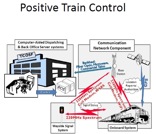
_
Positive train control (PTC) is a system that slow or stop a train without human intervention when the engineer makes a dangerous mistake. The modern version requires the train to be “aware” both of what it is doing and what is happening on the tracks ahead, using a combination of data radios, GPS, and cellular networks. If a discrepancy arises—a switch is open that shouldn’t be or the locomotive is passing a red signal—and the engineer doesn’t respond, the system takes control of the train, applying the air-brakes and shutting down the locomotive.
_
While it’s true that the vast majority of freight traffic and all passenger traffic travel on tracks with signals, even there, controllers can’t see their trains. They know only when a train has passed a given point—a switch or a signal that is wired into the grid. Those points are anywhere from one and a half to three miles apart, creating “blocks” of track. Controllers know when a train’s locomotive has entered or left a block, but not how fast it’s moving. They can talk to engineers by radio, but if they notice that a train has passed a red signal, all they can do is shout into the radio, and often they’re too late even for that. Positive train control, as conceived today, is intended not to replace control rooms and signals but to supplement them.
_
Positive train control (PTC) is a broad term for a system that monitors and controls train movements. Often this means using GPS navigation to pinpoint a train’s location and speed, and devices that can automatically slow the train if needed. The primary goal of PTC is to prevent train collisions, but they can also work to prevent derailments caused by excessive speed. This technology essentially monitors and controls a train’s motion in specific areas like sharp turns. This technology ensures that trains do not exceed the speed limit, preventing overspeed derailments.
_
Positive Train Control works by combining radio, cellular, and GPS technology with railway signals to allow trains to identify their locations relative to other trains on the tracks. Trains on a railway pass through signals that divide up lengths of track, during which the PTC system can notify an engineer if there is a train up ahead, if there is a stop up ahead, or if they need to slow down due to a sharp curve or turn. The important safety feature within PTC is that it can also force a train to stop if the engineer does not acknowledge a warning. For example, if a train whips by a signal to slow down, the PTC system can automatically force the train to stop if the engineer does not manually respond. This prevents an overspeed derailment when the engineer is distracted or incapacitated. PTC systems “work by monitoring the location and movement of trains, then slowing or stopping a train that is not being operated in accordance with signal systems and/or operating rules.” Positive train control is a technology that prevents two trains, traveling on a single track, from colliding with one another.
_
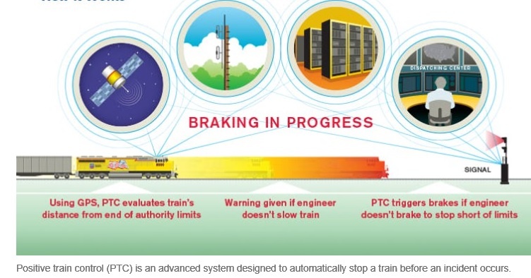
______
______
Continuous track circuit technology to detect rail fracture:
Ultrasonic testing for track faults are carried out once every few months, or drivers report unnatural sounds to engineers after passing over potentially defective tracks. The important sections like Chennai-Chengalpet, Chennai-Gummidipoondi and Chennai-Jolarpet have continuous track circuit technology. A fracture resulting in the separation of the rail would automatically break the circuit and switch the signal to danger (red). Such continuous track circuit is there in many stations between signals. The risk of cracks is more in the mid sections and less important routes like the Madurai-Sengottai route where very few trains are operated.
______
Rolling Computers:
On July 12, 2013, at a train station in Brétigny-sur-Orge, a southern suburb of Paris, a passenger train crashed at over 80 mph. The fault was a loose fishplate—the clamp that joins the ends of two lengths of metal rails. The fishplate wriggled out of position, jamming a railroad switch open, which caused the rear of the train to move onto a different track, and an intermediary train car to swing sideways, derailing and killing seven people. Tracks routinely undergo inspection to make sure any breaks, lose parts, or warped rails are caught early. Wear and tear on the tracks (which are subjected to the elements yearlong) is as inevitable as potholes. Traditionally these examinations have been done “by track inspectors, typically driving slowly [in a] truck that runs on the rails, or walking. But it gets easier to miss something if you do it week after week after week. More and more, railways are relying on “rolling computers” which may have lasers, radar, ultrasonic inspection, or different types of accelerometers that measure if there are irregularities. These rolling computers can operate either independently on track-bound trucks or be attached to a commercial train to inspect the track while the train is hauling freight or carrying passengers. In the U.S., some commuter and most freight railroads use a fishplate inspection device made by engineering company ENSCO. Here the rolling computer is attached to the end of a freighter, and “has cameras at 45-degree angles, which image the sides of the rail to detect the presence of any anomalies in a fishplate.” Not only is the computer faster and more accurate than the human eye, but it also keeps a record that contains more useful data than simply “broken” or “not broken.” You can also look at trends and degradation over time, and use this information to think forward and create a maintenance plan. Had such a system been employed by the French rail-line, the disaster might have been averted.
______
Oscillation monitoring system:
For Indian Railways, safety is important as thousands of trains use around 114,500 km tracks of its network – the world’s third largest. With regular use, the tracks develop cracks and fissures, including problems linked to loose nuts and bolts at the joints. If the tracks are less firmly anchored on the soil, it could lead to derailment. All these faults can now be detected in real time and recorded automatically to prevent derailment thanks to the oscillation monitoring system, a cutting-edge device weighing just 100 grams. The device has been designed and developed by a team of IIT-Kanpur’s mechanical engineering graduates, under the guidance of N.S. Vyas, professor and head, mechanical engineering, and the Railways’ Research Design and Standards Organisation (RDSO), Lucknow. The device, based on micro-electro mechanical system, can monitor track health more comprehensively and enable efficient track maintenance. The extremely handy package locates and logs track faults accurately with the help of the GPS (global positioning system), eliminating human errors and making train journeys safer. It has a battery life of 10 hours and can be recharged by USB port on computers. The device once placed on the floor of a running train’s coach measures and records vibrations. Any fault or irregularity on the tracks changes the pattern of vibrations. The device feeds all such data and locational faults into a fingernail-sized data storage card with the help of a GPS receiver. If the vibrations cross a certain threshold, especially in case of a critical fault, the device alerts engineers with audio-visual signals (beeps and flashing LEDs). Post- journey, the storage card is retrieved from the device and plugged into the computer for reading the track’s actual condition and analysis by the railways. The plan is to install at least three-four such devices on trains running on each route to monitor each track on a regular basis.
______
On Board Diagnostics:
On Board Diagnostics will also go a long way in boosting safety of rail travel. These are instruments embedded in the locomotives, to give accurate and realtime information about the performance of various parts, and give warning alerts if any reading is beyond the anticipated threshold. Currently, the motorman has to manually inspect the various components, and the diagnostics depends on the experience and knowledge of the individual. Saving the data farmed from multiple runs will provide more comparison points, and will continuously improve travel safety with increased use.
_____
Railtec: Derailment Protection:
The prevention of derailment is a priority issue. Wheel diagnosis at track speed is an essential requirement, because we don’t leave safety to chance. This track-based system measures the safety-relevant load status of a train and also detect force impacts which might be triggered by defective wheels. The measurement of noise emissions in compliance with standards helps rail companies to reduce disturbance in densely populated areas while identifying critical vehicle statuses in conjunction with measurements from defective wheels. The online measurement of vertical and lateral forces in loaded train sets helps to prevent derailment. Intelligent software solutions link on-track systems with higher-level control systems.
_____
Scout locomotives:
A popular but far-fetched proposal to make tracks safe is the usage of The Scout Locomotive to lead all fast trains. The small unmanned locomotives equipped with systems to detect damage in tracks and send across signals of the same are allowed to run at least a kilometre ahead of the train. In the case of damage in tracks, the locomotive will derail sending the main train information of the danger ahead. Usage of scout locomotives can save hundreds of lives, but the sheer size of the Railway network makes this far-fetched.
______
Satellite imagery and Geographical Information Systems are being used by the Indian Railways to improve safety. The systems are being developed with a partnership with ISRO. After an accident, the satellites can be used to monitor the scene and understand the terrain. The satellites can also be used to trigger hooters to warn approaching vehicles in unmanned railway crossings.
_____
GE uses AI to find rail track flaws that could cause derailments:
GE is using AI-equipped locomotives to automate detection of “sun kinks,” rail track deformations that can cause derailments. AI models can scan video footage to identify track flaws, pinpointing their location and working out whether they pose a danger. Artificial intelligence (AI) could allow rail operators to more accurately detect issues on their tracks, creating a safer and more reliable rail network. GE’s current “smart freight” locomotives are equipped with a set of high-definition video cameras that continually capture the track ahead of the train. A densely architected onboard datacentre processes the camera signals, using AI to find physical defects on the rails. If a deformation is identified, it’s analysed in real-time to determine whether it could derail the locomotive. If it’s found to be a risk, a warning can be issued before the train’s automatically slowed down.
_____
_____
Are trains designed such that if a person were about to get run over, he could lie flat between the tracks and avoid death as the train passed over him?
While you could get away with the lie-flat-between-the-tracks gambit (and people have), it’s far from a sure thing. Train cars conform to certain mandatory design parameters, but these are aimed at ensuring that they can fit through tunnels and pass trains on adjacent tracks without unpleasantness, not at providing you an easy out for avoiding catastrophe. Perhaps the one marginally relevant specification is that a train car’s axles must clear the top of the rails by at least 2¾ inches. If the distance between the tops of the rails and the track bed beneath were great enough (and you were compact enough), you might get run over by a train and live. Or you might not. It isn’t unusual for parts, equipment, objects, etc., to protrude below the rails or to come loose and drag beneath the train.
_____
Where is the Safest Place to sit on a Train?
Conventional wisdom holds that the front car of a train is the most dangerous place in the event of a head-on collision, while the last car is less safe if the train is rear-ended. But, in fact, trains are nine times more likely to derail than to hit another train or car head-on or to get hit from behind, according to the Federal Railroad Administration (FRA). The administration found that there were about 13,200 derailments from 2005 to 2014, compared with about 1,450 collisions. Studies suggest that broken rails or welds are the leading cause of derailment on main tracks, and these problems more often cause derailments near the front of the train. Overall, choosing a car located one or two back from the middle of the train may be the safest bet. In general, aisle seats are safer than window seats, where a passenger is more likely to come in contact with broken glass or be thrown from the train. Safety experts also recommend choosing a rear-facing seat, because a person sitting there is less likely to be thrown forward during a collision. Trains are more likely to hit something side-on than head-on or from behind, according to the FRA. If the train has a café car, it’s a good idea to avoid spending too much time there, because the rigid tables can become dangerous if the train suddenly breaks or hits something.
______
China unveils world’s first driverless train that can run without tracks:
Chinese rail transit firm CRRC has developed driverless train or smart bus that can run without tracks. The smart bus or the Autonomous Rail Rapid Transit (ART) was developed by the research arm of CRRC Zhuzhou Locomotive Co., Ltd., which produces key parts for China’s high-speed railway. The vehicle is about 30 meters long and comes with sensors that can read the dimensions of roads and plan its own route. The new train has a life span of 25 years and is said to be non-polluting. The train identifies the pavement and has various sensors to emit travel information to the train. The first car is just over 100 feet in length with a maximum passenger load of 307 people. It has a top speed of 70 kilometres an hour and after ten minutes of charging can travel 25 kilometres. The new system is set to go into operation in 2018.
_______
_______
Derailment in Indian railways:
Indian Railways (IR) is a State owned national transporter, responsible for rail transport in India. It is owned and operated by the Government of India through the Ministry of Railways. India has the third biggest rail network in the world. It covers at least 115,000 km in distance, and has 7112 stations and 131,200 railway bridges. Every day, around 23 million passengers use trains as a means of transport. In fact, between 2014 and 2015, at least eight billion people were transported by Indian Railways. However, the sole operator has not been able to keep up its maintenance and improvement work in accordance with the level of expectation. India does not have any railways classified as high-speed rail (HSR), which have operational speeds in excess of 200 km/h (120 mph). India’s Prime Minister Narendra Modi approved the choice of Japan to build India’s first high-speed railway. The planned rail would run some 500 km (310 mi) between Mumbai and Ahmedabad, at a top speed of 320 km/h (200 mph). It would cost about ₹980 billion (US$15 billion) and be financed by a low-interest loan from Japan. India will use the wheel-based 300 km/hr HSR technology, instead of maglev technology. India is expected to have its HSR line operational from 2025 onwards, once the safety checks are completed.
_
Causes of rail accidents in India:
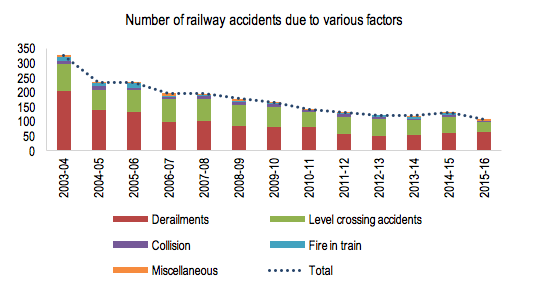
The number of railway accidents due to various causes is shown in the graph above. Majority of the accidents were caused due to derailments (60%), followed by accidents at level crossings (33%).
_
Let’s look at some facts:
- A total of 168 people died in 131 railway accidents in India in 2014-2015, up from 103 fatalities in 117 accidents in 2013-2014. (India’s accident rate per million train kilometres – 0.20 – in 2012-13 compares favourably with that of advanced railways in Europe – Germany and France, for example, both recorded 0.17 accidents per million train kilometres in 2012 – but India’s figures mask major deficiencies.)
- Derailment was the reason for 60 of the 131 accidents in 2014-2015.
- The majority of these accidents – 115 – were attributed to human failures – “failure of railway staff and failure of persons other than railways staff”. Curiously, track failures, according to official data, did not contribute to a single accident. But some experts believe that this doesn’t quite square up with the state of India’s railway tracks. Now, consider this:
- India has nearly 115,000km (71,457 miles) of railway tracks.
- A 2015 assessment by the railways ministry says some 4,500km of track should be “renewed” every year.
- But a lack of funds has meant that construction of new tracks and replacement of the old are not happening at the desired pace. Only 2,100km of tracks were targeted for “renewal” in 2015. The fracturing of tracks – often caused by expansion of tracks in summer, and contraction in winter – is “the nightmare of the [railways] engineering department”, an internal railways memo in 2014 said. According to a 2015 government paper, 40 per cent of the lines on the Indian railways are being used beyond their official capacity. A task force on safety, which was set up after the Indore-Patna Express derailed near Pukhrayan in Kanpur last November and killed over 150 people, found that rail fracture and inadequate maintenance are often the cause of mishaps. The report, which was drafted by senior railway officials, called for technology upgrade for maintenance, and said that “rails is a complex exercise and must be automated as much as possible to reduce dependence on human judgement”.’ Currently, the method for preventing accidents is decidedly low tech. Railway employees trudge up and down the tracks, carrying heavy equipment, manually inspecting the tracks for problems. According to various reports, the number of employees hired to manually inspect the tracks range from 100,000 to 200,000.
__
Safety in Indian railways:
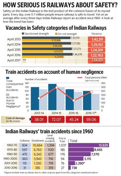
Indian railway is not serious about safety as seen from the figure above. Over-worked tracks and inadequate maintenance are one of the main reasons for rail accidents in India. Majority of the rail tracks have been used beyond their capacity, and some of the most fatal accidents in recent years, including the Indore-Patna Express derailment , took place on such railway sections. A Standing Committee report on Railways’ safety and security in December last year identified under-investment in Railways as one of the reasons for more rail accidents. The report stated that while passenger and freight traffic has increased by 1,344 per cent and 1,642 per cent respectively from 1950 to 2016, the Railways’ route kilometres have increased by a mere 23 per cent. This suggests that the railway lines are severely congested. So under-investment in the railways has resulted in congested routes, inability to add new trains, reduction of train speeds and more rail accidents. Therefore, avoiding such accidents in the future would also require significant investments towards capital and maintenance of railways infrastructure. The Standing Committee report also observed that the modern Linke-Hoffman Busch (LHB) coaches do not witness higher casualties in case of derailment as the coaches do not pile on each other, and recommended that the Indian Railways completely switches to LHB coaches.
_
However, one should not rush to blame poor quality infrastructure for the increasing number of accidents. Between 2012-13 and 2016-17, 47% of consequential rail accidents took place due to failure of railway staff. Less than 5% were due to equipment failure or sabotage. “Human factor cannot be replaced no matter how much money is put in for safety. There is a need for increased vigilance,” said a member of the Railway Board, requesting anonymity. The Twelfth report of the Standing Committee on Railways (2016-17) on ‘Safety and Security in Railways” had also underlined the need for taking corrective measures over lapses by the railway staff which include carelessness, poor maintenance, adoption of short-cuts, non-observance of safety rules. Over 700,000 people work on safety-related operations at the country’s largest employer, according to Indian Railways’ response to a Parliament question. A small slip by one of them, or a single flaw in the 66,030km track criss-crossing the country can affect one or more of 10,773 locomotives, 63,046 coaches and 245,000 wagons, jeopardizing the 23 million passengers and three million tonnes of freight that the network carries every day. As such, there’s the 16% shortage in safety staff. The total number of vacancies in safety staff was around 124,201. And this number has been growing steadily over the decades. The shortage means that others have to work more and harder. Speaking on condition of anonymity, a loco (locomotive)-pilot (engine driver) said: “Our duty hours range from 12-16 hours a day and then, there are the inhuman conditions in which we work. No toilets, no lunch break and engines have no seats.” “How do you expect us to give our best,” he asked? He adds that the government has failed to install toilets in all locomotives.
_
A senior railway ministry official who asked not to be identified said, “We are trying our best to keep updated with the railway safety standards and devices. We have installed systems like Block Proving Axle Counters (BPAC), Auxilary Warning System (AWS), Train Protection and Warning System (TPWS), Train Collision Avoidance System (TCAS), etc. to aid frontline staff and reduce human dependence.” These systems are yet to cover the entire network. Former railway board chairman Arunendra Kumar agrees: “The problem in India is not of safety standards but the execution of standards.”
_
The August 19, 2017, accident near Khatauli station, which killed 23 passengers, is a warning of the dangers of rising over-utilisation of the trunk routes. The section where the accident occurred carries trains far in excess of its capacity. It carries 35 trains daily against capacity of 25 trains with two hours for maintenance that is over-utilisation of 140%. For optimal performance (maintenance, operations and safety) utilisation should be less than 90% of the capacity. Reportedly, the train-controllers refused block (temporary suspension of traffic for carrying out a routine or emergency maintenance) to replace a fractured rail. The maintenance staff started repair, just when the train approached the site at full speed and derailed. Over-utilisation of line capacity, rail fracture and carrying out repairs without block or with inadequate block has become a common feature of IR’s working. According to the latest data, utilisation exceeds capacity on 65% of the high density sections; utilisation is 120-150% on 32% of the sections and more than 150% on 9% of the sections.
_
Rail fractures are a symptom of overstressing the track. Congestion on the lines leaves little time for maintenance, which is hurriedly carried out in the time available. On the IR, about 5,000 rail fractures are reported annually. The real number is much higher, because it is an open secret in IR that only those rail fractures that cause detention of trains are reported. On better railway systems rail fractures are very rare. A rail with incipient cracks will be detected by inspection and removed before it fractures in track. With inadequate maintenance and increased wear and tear, the track also requires frequent renewals. Total length track renewal is 1.18 lakh km which will take at least 40 years to complete. Maintenance of rolling stock also suffers as often there is less time at the terminals to carry out safety inspections and maintenance.
_
Measures to reduce derailments in India:
Upgradation of Track Structure consisting of Pre-stressed concrete (PSC) sleepers, 52 Kg/60 Kg high strength (90 kg/square mm ultimate tensile strength) rails on concrete sleepers, fanshaped layout on PSC sleepers and Steel Channel Sleepers on girder bridges have been adopted on some of the routes. Track structure is being standardized with 60 kg rails and PSC sleepers on all the Broad Gauge routes, especially on high density routes to reduce fatigue of rails under higher axle-load traffic. New track construction and replacement of over-aged tracks is being done by PSC sleepers only. To improve maintenance and reliability of assets, efforts to eliminate fish-plated joints by welding single rails into long welded rails were continued. During relaying/construction of new lines/gauge conversion, long welded rails are laid on concrete sleepers. Long rail panels of 260 M/130 M length are being manufactured at the steel plants to minimize number of welded joints. Turnouts are also being improved systematically. There is progressive shifting to flash butt welding which is superior in quality as compared to Alumino Thermic (AT) welding. All rails and welds are ultrasonically tested as per laid down periodicity. Self Propelled Ultrasonic Rail Testing (SPURT) Cars are being used for Rail flaw detection. There has been progressive use of Tie Tamping and ballast cleaning machines for track maintenance. Also, sophisticated Track Recording Cars, Oscillograph Cars and Portable Accelerometers are being used progressively. Two Rail Grinding Machines are being procured. Rail Grinding and rail lubrication for enhanced rail life and reliability has been recently introduced. Electronic monitoring of track geometry is carried out to detect defects and plan maintenance. Modern bridge inspection and management system has been adopted, which includes non-destructive testing techniques, under water inspections, fiber composite wrapping, mapping unknown foundations and integrity testing, etc. Based on threat perceptions due to adverse weather conditions or external interference, patrolling of railway tracks including night patrolling as well as intensified patrolling during foggy weather is carried out at vulnerable locations regularly. Progressive fitment of tight lock Central Buffer Coupler (CBC) in lieu of screw coupling in new design coaches by ICF has been carried out to prevent the coaches from climbing over each other in unfortunate event of an accident. Design of passenger coaches with features of crashworthiness to absorb most of the impact energy, leaving the passenger area unaffected has been developed and coaches are being manufactured accordingly. For enhancing safety and reliability of passenger coaches, the suspension systems are being re-designed with air springs at secondary stage capable to maintain constant height at variable loads. Air springs have been developed and are being fitted on all the newly built EMU and DMU coaches for suburban trains. Air springs have now been developed for mainline coaches as well and manufacture of such coaches has already been commenced. Wheel Impact Load Detector (WILD) are being deployed in a phased manner. A report submitted by a panel of experts appointed by the Indian government said there was an “urgent need to modernize the key revenue generating assets of the railways such as tracks and bridges.” It suggested modernization of 19,000 kilometers of existing tracks.
______
______
Terror and sabotage derailment:
_
A Polish 14-year-old caused a lot of damage in downtown Lodz few years ago by rigging a TV remote control that let him switch track points on the city’s tram system. He derailed four trains and injured dozens of people but it was lucky nobody was killed. Sabotage attempts to derail trains in Malda and Dhanbad in India were thwarted in 2017. Cases of man-made obstructions were discovered at Malda and Dhanbad divisions by alert railway staff on time, thereby averting major derailments, said a senior railway ministry official. According to the official, the loco pilot of a passenger train detected fish plates missing between Koderma and Maheshpur under Dhanbad division and stopped the train. Rail traffic was stopped for three hours and an FIR has been lodged in the matter. In the second incident, fittings were found missing on a track between Bariarpur and Ratanour in Malda division. Train movement was stopped and it resumed only after the replacement of fittings, the official said adding an FIR has been lodged in this matter too. Earlier, a major mishap was averted on January 24 after a Jan Shatabdi Express loco pilot stopped the train spotting a 15-feet rail piece on the track near Diwa in Mumbai. On January 23, another possible train accident was averted at Hajipur in Bihar due to an alert patrolling team of the railways. Two stone slabs that were placed on the track were detected on time and removed. Alarmed by these incidents, Indian railway minister has sought an NIA probe into the recent spate of derailments suspecting sabotage. Railway board member (traffic) Mohd Jamshed has also cited 45 such cases involving outside interference on the tracks affecting train movement and causing loss of lives and revenue.
_
French police in September 2017 have issued a confidential note based on an analysis of “jihadist propaganda,” warning of possible lone-wolf attacks causing trains to derail. Due to recent jihadist propaganda urging plans for train derailment, particular attention should be paid to any reports of intrusion or attempted sabotage on the premises of railways, a seven-page report compiled by the police directorate reads. The document, which focuses on aspects of “jihadist propaganda” over the past three months, warns that terrorists are instructed to make explosives “as shown in tutorials,” conceal their radicalization, calling on “lone wolves” to cause “train derailments, forest fires or food poisoning” in Europe. A Karachi-based Fake Indian Currency Note (FICN) smuggling kingpin, who is also a known agent of Pakistani spy agency Inter-Services Intelligence (ISI), has emerged as a pivot to the conspiracy to derail trains in India by using local criminals according to Indian intelligence agencies.
_
Terrorist attacks to derail a train would be difficult:
Past experiences suggest that terrorists who want to derail a train are facing a much more complex task than just leaving a penny on the rail. A report from by the Mineta Transportation Institute gives a number of good reasons why derailment disasters are so rare. The main reason is that blowing up a track is tougher than it sounds. Getting a bomb to go off at the right time is difficult. Timers are unreliable if the trains do not run precisely on time, and pressure triggers do not always work. Sabotaging the switching points would be more reliable, but it takes more cleverness. Mechanical sabotage of all kinds (high- and low-tech) derailed trains with 76 percent success rate in the Mineta report’s samples — but it was much more rare than setting bombs. Only 25 out of the sample of 181 derailment attempts were acts of mechanical sabotage.
_
In 1995, an Algerian terrorist group called the Groupe Islamique Armé tried to bomb a line of the TGV, France’s high-speed rail, near Lyon. It was an attack with al-Qaeda-like aspirations. The psychological effect of an explosion on the train would have been enormous. France’s TGV was the first high-speed rail system in Europe and today remains a source of national pride. The bomb misfired, and the suspect eventually died in a shootout with police. French officials knew the GIA wanted to cause mayhem any way it could — including hijacking an airliner meant to smash into the Eiffel Tower a few months before. But officials resisted the urge to post metal detectors at all French train stations and force millions of passengers to take off belts and shoes. Instead, they doubled the number of inspectors sweeping the rails every morning for bombs. French authorities … emphasize the importance of deploying limited resources in ways that terrorists cannot predict, persuading them that they face a high risk of being apprehended, write the Mineta authors. The point is that airport-style security would ruin everything good about a high-speed train, so light security lines have remained the rule with European rail. Full security on any train system is impossible. Intriguingly, the Mineta study looked at 181 derailing attempts around the world since 1920 and found a full third of them in “South Asia” — India, Sri Lanka, Pakistan. The deadliest attacks have occurred in the developing countries, says the report, probably because poor nations lack the budget to sweep and patrol their train systems.
______
______
High speed rail (HSR) and its derailment:
High-speed rail is a catchall term with several definitions. The Federal Railroad Administration says it starts at a hundred and ten mph, while the International Union of Railways says a hundred and fifty-five. But whichever definition one favors, the rails themselves must be carefully designed to handle the physical forces imposed upon them by multi-ton trains moving at high velocity. High-speed rail (HSR) has operational speeds in excess of 200 km/h (120 mph) and HSR technology could be wheel based or maglev. Travellers will most likely want high-speed trains like those in Europe and Japan. But high-speed trains are expensive to build and maintain. They also work best on dedicated passenger railways. Furthermore, the railways must reach more cities and destinations than they do now. So, making railroads a major form of passenger transportation will require investments to expand and improve the railway systems. High-speed trains like France’s TGV train may dominate the rails in the future, but occasionally they get in spectacular wrecks, too, just like a regular old train. New technologies such as magnetic levitation or maglev trains may increase train speed even more. These trains don’t have wheels but rather travel on superconducting magnetic rails, but they’re expensive to build and maintain.
_
Generally, high speed rail runs at speeds above 200 km/h (120 mph) and often operates on dedicated track that is surveyed and prepared to accommodate high speeds. Japan’s Shinkansen (“bullet-train”) commenced operation in 1964, and was the first successful example of a high speed passenger rail system. The fastest wheeled train running on rails is France’s TGV (Train à Grande Vitesse, literally “high speed train”), which achieved a speed of 574.8 km/h (357.2 mph), twice the take-off speed of a Boeing 727 jetliner, under test conditions in 2007. The highest speed currently attained in scheduled revenue operation is 350 km/h (220 mph) on the Beijing–Tianjin Intercity Rail and Wuhan–Guangzhou High-Speed Railway systems in China. The TGV runs at a maximum revenue speed of 300–320 km/h (190–200 mph), as does Germany’s Inter-City Express and Spain’s AVE (Alta Velocidad Española).
_
The running safety of high-speed trains has become a major concern of the current railway research with the rapid development of high-speed railways around the world. The basic safety requirement is to prevent the derailment. The root causes of the dynamic derailment of high-speed trains operating in severe environments are not easy to identify using the field tests or laboratory experiments. Numerical simulation using an advanced train-track interaction model is a highly efficient and low-cost approach to investigate the dynamic derailment behavior and mechanism of high-speed trains. High-speed rail in the West has a fairly good safety record, but experts are worried that there are plans to run trains faster than any other line in the world. Trains will travel at 225mph, rising to 250mph within a few years. Most high-speed lines, including Britain’s existing Eurostar, run no faster than 186mph and the world’s current fastest rail-based trains, France’s TGV travel at 200mph. Some trains on the new Chinese high-speed network used to run at 220mph, but were reduced to 186mph last year on safety grounds. Professor Peter Woodward, one of the world’s leading experts on the geo-engineering of railways, said that high-speed running created “new problems” in track which “may threaten the stability and safety of the train”. In papers lodged with the Government’s Engineering and Physical Sciences Research Council (EPSRC), Prof Woodward warned that speeds as high as 225 to 250mph could trigger “significant amplification of train-track vibrations” causing “rapid deterioration of the track, ballast and sub-ballast, including possible derailment and ground failure”. Prof Woodward was worried about “ground waves” of vibration, known as Rayleigh waves, developing in the rail at a certain speed. The analogy is that of an aircraft going through the sound barrier. As “critical track velocity” was approached, the track would “start to undergo strong ground vibrations,” rippling visibly along the rails in front of the train. “It is possible that if the train was allowed to run at this critical track velocity it would derail at high speed,” he warned.
_
In most cases, high-speed rail travel is time- and cost-competitive with air travel when distances do not exceed 500 to 600 km (310 to 370 mi), as airport check-in and boarding procedures may add as many as two hours to the actual transit time. Also, rail operating costs over these distances may be lower when the amount of fuel consumed by an airliner during takeoff and climbout is considered. As travel distance increases, the latter consideration becomes less of the total cost of operating an airliner and air travel becomes more cost-competitive. Some high speed rail equipment employs tilting technology to improve stability in curves. Examples of such equipment are the Advanced Passenger Train (APT), the Pendolino, the N700 Series Shinkansen, Amtrak’s Acela Express and the Talgo. Tilting is a dynamic form of superelevation, allowing both low- and high-speed traffic to use the same trackage (though not simultaneously), as well as producing a more comfortable ride for passengers.
_
Over the years, advancements in active and passive safety have reduced considerably the accident risk, making rail travel to one of the safest modes of transportation. The introduction of active safety measures to reduce the probability of unwanted events has practically eliminated derailments caused by over-speeding or high-speed train collisions. However, derailments due to mechanical failures affecting the wheelset guidance on rails continue to occur, despite refined inspection techniques as well as more reliable vehicles, Moreover, certain types of derailment causes such as vandalism/terrorism or environmental factors are not likely to be eliminated by active measures in the near future.
________
On minimizing derailment risks and consequences for passenger trains at higher speeds: a 2009 study:
Despite being one of the safest modes of transportation, railway accidents and incidents still occur, sometimes with derailments as an attendant phenomenon. A multitude of factors may bring high-speed passenger rail vehicles [> 200 km/hr] into a derailed condition such as mechanical failures in the wheelset–track interface (wheel, axle, rail failure, etc.), impact with object on the track, earthquakes, etc. Depending on various aggravating factors (track geometry, switches and crossings, etc.), the derailed wheelsets may start to deviate laterally. In such situations, the risk of catastrophic outcomes can be diminished by minimizing the consequences.
_
The first part of this study deals with the possibility of preventing wheel climbing derailments after an axle journal failure by implementing mechanical restrictions between the wheelsets and the bogie. A multi-body system (MBS) computer model is developed to account for such an axle failure condition, which is successfully validated by comparing the pre-derailment sequence of events with two authentic cases. An extensive parameter analysis on the maximum vertical and longitudinal play between the wheelset and the bogie, required to prevent a highspeed power or trailer car to derail, is performed for various combinations of running conditions in curves.
_
Once an actual derailment has occurred on conventional passenger trains at 200 km/h, extensive MBS simulations are performed on the feasibility of utilizing alternative substitute guidance mechanisms, such as low-reaching parts of bogie frame, axle box, or brake disc, as means of minimizing the lateral deviation. Results are presented in terms of geometrical parameters that lead to a successful engagement with the rail for a total of 12 different derailment scenarios. These are caused by an axle journal failure, an impact with a small object on the track, or a high rail failure.
_
Minimizing the lateral deviation is also investigated by means of restraining the maximum coupler yaw angle and altering the bogie yaw stiffness. Time-domain simulations are also performed in terms of lateral track forces and derailment ratio when negotiating a tight horizontal ‘S-curve’. Further, the articulated train concept is investigated in terms of the post-derailment vehicle behaviour after derailments on tangent and curved track at a speed of 200 km/h. In this respect, a trainset consisting of one power car and four articulated passenger trailer cars is modelled in the MBS software. Results in terms of lateral deviation and maximum carbody roll angle are presented as a function of different inter-carbody damper characteristics and running gear features. The feasibility of these damper characteristics is also tested in terms of lateral track forces and derailment ratio when negotiating a tight horizontal S-curve.
_
Mechanical restrictions limiting a wheelset’s movements relative to its bogie frame might be beneficial in cases of axle failure on the outside of the wheel, at the journal bearing. This insight emanated from empirical observations involving the Swedish high-speed tilting train X 2000, which limited the consequences to a minimum after a couple of axle failure incidents. Out of four such incidents, only one case led to a derailment with fairly modest consequences. Furthermore, empirical evidence from Sweden and abroad suggested, among others, the possibility of utilizing alternative substitute guidance mechanisms as a means for reducing the potentially very dangerous lateral deviation of the running gear from the track centre line. In addition, the articulated design concept has been suggested to have positive effects on the outcome of a derailment, mainly based on a number of observations on the French TGV.
_
Substitute guidance mechanisms:
For low-reaching mechanisms connected to the vehicle, at least three different possibilities can be identified: bogie frame, brake disc and axle journal box as seen in the figure below. The intended purpose of the substitute guidance mechanisms is to guide laterally and stabilise a derailed running gear by simply engaging with the appropriate rail according to figure below. In order to initiate as well as to maintain a successful lateral guidance, geometrical and strength requirements need to be fulfilled. In addition, mechanisms should be able to cope with track discontinuities, i.e. traversing switches and crossings, in a derailed condition so that a further aggravating situation is avoided.
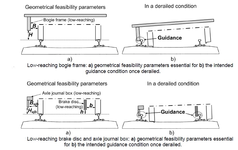
_
Based on the computational results obtained in the current study, further supported by empirical observations, the following features are perceived as capable of improving a rail vehicle’s derailment worthy design:
- mechanical restrictions that limit the wheelset’s longitudinal and vertical movements relative to the bogie frame
- low-reaching lateral guidance mechanisms attached on to the bogie frame (bogie frame parts or transversal beams with a staggered design) or the axles (journal boxes or brake discs)
- low-reaching vertical support mechanisms (transversal beams or bogie frame parts)
- small vertical distance between carbody height of C.G. and centre coupler pivot centre
- small centre coupler yaw angle for the conventional train configuration
- powerful inter-vehicle longitudinal dampers for the articulated train configuration
______
José Luis López Gómez, inventor of a high-speed train guidance system:
Railway technicians have long known that the ‘wheel/rail connection’ – the contact point between the wheel and the rail – is not only responsible for significant wear-and-tear on both wheels and rails but also essential to a train’s stability. When contacting the rail, train wheels make a small elliptical footprint, which significantly reduces friction. Unlike a car tire that makes a flat imprint on the road across the entire width of its tread, a train wheel has a smaller diameter at the outside than on the inside. This slightly conical shape both minimises the surface area that comes in contact with the train track and allows the wheels to take a turn without sliding or grinding. As a train travels around a curve, the outer wheels have a slightly longer distance to travel than the inner wheels. Thanks to their conical shape and smaller diameter of their outer edge, the outer wheels travel this extra distance, ideally spinning at the same speed as the inner wheels.
_
A new way of guiding train wheels:
López Gómez’ innovation, patented at the EPO in 2007, optimises this movement by detecting the precise speed at which the wheel is rotating and then calculating exactly which portion of the wheel is contacting the rail. Using this information, the train’s tilting suspension system can ensure that the optimal contact point is maintained. The technology is particularly useful when a train is entering or exiting a curve, where current technologies have not been able to improve contact between the wheel and the rail in a way that makes train rides safer and more comfortable. Although this system has not yet been fully implemented, it is already operating in a number of test trains – with encouraging results. The tests show that the optimal area of both the wheels and the rail are coming into contact with each other. The system prevents squeaking noises, limits wear-and-tear and significantly improves the comfort of the ride. José Luis López Gómez’ patented method for optimising the guidance of railway vehicles is applied to free-wheel train vehicles, whose wheels rotate independently from each other, such as Talgo high-speed trains.
_
The invention utilises an electronic system that detects when wheels deviate from their central and optimal position on the rails. It also includes an automatic mechanical apparatus for moving the wheels back into this optimal position. When rounding a turn, centrifugal force causes a train’s wheels to move sideways on the rails – often moving them away from the optimal turning position. Because of their conical shape (slightly larger on the inside and smaller on the outside), the wheels on the outside will contact the rail with a larger circumference than the inside wheels. The increased circumference travelled by the outer wheels allows them to cover the extra distance of the turn. Ideally, they spin at the same speed as the inner wheels, which use their smaller outer edge to compensate for the reduced distance on the inside of the curve. Should the wheels move too far sideways, a 28-millimetre-high ridge on the inside edge of the wheel (called a flange) will catch on the rail and act as a failsafe to stop the train from derailing. Contact between the flange and the rail results in significantly increased friction, often producing screeching sounds and causing the wagon to shudder. López Gómez’ system uses precise computer technology to detect the rotational speed at which a train wheel is travelling and then calculate where it is contacting the rail. When the wheel deviates from its optimal position, an automatic mechanical system moves it back to the best contact point.
______
Measures to prevent derailment of Shinkansen train in Earthquake:
The Shinkansen (new trunk line), colloquially known in English as the bullet train, is a network of high-speed railway lines in Japan operated by five Japan Railways Group companies. The maximum operating speed is 320 km/h (200 mph) (on a 387.5 km section of the Tōhoku Shinkansen). Test runs have reached 443 km/h (275 mph) for conventional rail in 1996, and up to a world record 603 km/h (375 mph) for maglev trains in April 2015. The Shinkansen uses 1,435 mm (4 ft 8 1⁄2 in) standard gauge in contrast to the 1,067 mm (3 ft 6 in) narrow gauge of older lines. Continuous welded rail and swingnose crossing points are employed, eliminating gaps at turnouts and crossings. Long rails are used, joined by expansion joints to minimize gauge fluctuation due to thermal elongation and shrinkage. A combination of ballasted and slab track are used, with slab track exclusively employed on concrete bed sections such as viaducts and tunnels. Over the Shinkansen’s 50-plus year history, carrying over 10 billion passengers, there have been no passenger fatalities due to derailments or collisions, despite frequent earthquakes and typhoons. There have been two derailments of Shinkansen trains in passenger service. The first one occurred during the Chūetsu earthquake on 23 October 2004. Eight of ten cars of the Toki No. 325 train on the Jōetsu Shinkansen derailed near Nagaoka Station in Nagaoka, Niigata. There were no casualties among the 154 passengers. Another derailment happened on 2 March 2013 on the Akita Shinkansen when the Komachi No. 25 train derailed in blizzard conditions in Daisen, Akita. No passengers were injured. In the event of an earthquake, an earthquake detection system can bring the train to a stop very quickly. A new anti-derailment device was installed after detailed analysis of the Jōetsu derailment. Japan Railway Companies (the JR Group) and the Japan Railway Construction, Transport and Technology Agency (JRTT) and the RTRI are promoting the joint development of rolling stock guides as an off-track prevention measure, rail turnover prevention devices for the effective use of the guides, glued insulation rails as a measure against earthquake-related issues, improved expansion joints, derailment and off-track prevention guards on the ground as measures to prevent derailment of Shinkansen train in earthquakes.
______
______
Maglev:
Maglev is short for Magnetic Levitation in which trains float on a guideway using the principle of magnetic repulsion.
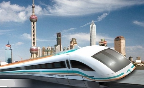
_
Note:
Levitation: The state of rising and floating in the air in apparent defiance of gravity.
Repulsion: The tendency of particles or bodies of the same electric charge or magnetic polarity to separate
_
In order to achieve much faster operation over 500 km/h (310 mph), innovative maglev technology has been researched since the early 20th century. The technology uses magnets to levitate the train above the track, reducing friction and allowing higher speeds. An early prototype was demonstrated in 1913, and the first commercial maglev train was an airport shuttle introduced in 1984. The Shanghai Maglev Train, opened in 2003, is the fastest commercial train service of any kind, operating at speeds of up to 430 km/h (270 mph). Maglev has not yet been used for inter-city mass transit routes.
_
Magnetized coils run along the track called a guideway. These repel the large magnets on the train’s undercarriage, allowing the train to levitate between 0.39 and 3.93 inches (1 to 10 cm) above the guideway. Once the train is levitated, power is supplied to the coils within the guideway walls to create a unique system of magnetic fields that pull and push the train along the guideway. The electric current supplied to the coils in the guideway walls is constantly alternating to change the polarity of the magnetized coils. This change in polarity causes the magnetic field in front of the train to pull the vehicle forward, while the magnetic field behind the train adds more forward thrust. A Maglev thus requires three major components:
- A large electrical power source
- Metal coils lining a guideway or track
- Large guidance magnets attached to the underside of the train
Maglev trains float on a cushion of air, eliminating friction. This lack of friction and the trains’ aerodynamic designs allow these trains to reach unprecedented ground transportation speeds of more than 310 mph (500 kmph). Developers say that maglev trains will eventually link cities that are up to 1,000 miles (1,609 km) apart. At 310 mph, you could travel from Paris to Rome in just over two hours
_
Maglev cannot derail:
Maglevs are better than traditional trains in a lot of ways, one of which is that it cannot derail. But this does not mean that maglevs are 100% safe. The fatal crash at the German test track in 2006 has proved that a human error can trip even with the best designed high speed transport system. On Sept. 22, 2006, a Transrapid test train in Emsland, Germany had 29 people aboard during a test run when it crashed into a repair car that had been accidentally left on the track. The train was going at least 120 mph (193 kph) at the time. Most passengers were killed in the first fatal accident involving a maglev train. The accident however proved that the German maglev did not derail even though it rammed into a 50 ton maintenance vehicle at 125 mph (200 kph). It is unrealistic to discourage the development of maglevs because of one train crash, especially when it carries less risk and higher benefits as compared to the traditional trains.
______
______
Research on derailment:
The researches of derailment are classified into mainly three fields. First field is a research of derailment mechanism. The second field is investigations of safety assessment for derailment. The last field is derailment detection.
_____
Theory of random energy analysis for train derailment: a 2003 study:
Three fundamental problems in the calculation of train derailment abroad and at home were pointed out and the solutions to these problems were presented. The theory of random energy analysis for train derailment was suggested. The main contents of this theory are as follows: geometric criterion of derailment; method of random energy analysis of transverse vibration of train track system; mechanism of derailment and energy increment criterion for derailment evaluation; calculation of the entire derailment course of train. This theory is used to calculate a case of freight train derailment, which corresponds to an actually occurring accident. Another derailment test, in which the train is judged not to be derailed, is calculated and the maximum vibration response is well correspond to the test results. And the effectiveness and practicability of the theory are proved by the two calculated cases.
_____
Analysis of wheel–rail interaction using FE software: a 2004 study:
One of the most important questions relating to the exploitation of cars and locomotives on the railways of the Central and Eastern Europe countries is the increased wear of the working surface of the wheels. In particular, this concerns their flange zones. In addition, wear also occurs on lateral surfaces of the rail heads. The amount of wear varies for different track locations and for different rolling stock. It involves both plastic deformations, and abrasion of surfaces. The cause of this phenomenon may be high dynamic forces at the wheel–rail contact that as caused by bad maintenance, both of a rolling stock, and track and absence of effective and appropriate use of lubrication. However, the most important questions are related to the choice of wheel and rail profiles. It is quite obvious that these profiles should correspond to each other and that a change of one of them should not occur without change of the other. Current practice of railways in some countries says the opposite. In this work, an attempt to analyze the wheel–rail contact interaction for various profiles of wheels and rails, including severely worn ones, is made. In this article, research into the influence of interacting wheel and rail profiles on the distribution of contact zones and stresses is presented. The influence of contact forces on the deformation of rolling carload wheels and rails, and the influence of this deformation on the redistribution of the contact stresses is also investigated. The quasi-Hertz method as well as a finite element (FE) method were included as basis of mathematical simulation. With these tools, distributions of contact zones for different angles of attack of the wheelsets were defined. The problem was solved in three-dimensions. The offered technique to solve the contact problem has been used for the improvement of operating wheels. As a result of the research, distributions of contact zones and stresses for various wheel and rail profiles have been determined. These investigations are used as the basis for the development of new wheel and rail profiles from which recommendations on improvement of profiles may be given. In particular, new designs of the rail heads are developed, rolled and are now tested on railways in Ukraine.
_______
Analysis of Derailments by Accident Cause: a 2011study:
The risk of train derailment associated with rail transportation is an ongoing concern for the rail industry, government, and the public. Various approaches have been considered or adopted to analyze, manage, and reduce risk. Upgrading track quality has been identified as one possible strategy for preventing derailment. Upgrading track class is likely to prevent certain track-related derailments; however, this upgrade may also increase the risk of certain types of equipment failure that are more likely to occur at higher speeds. Consequently, more sophisticated approaches need to be developed to examine the interactions among accident causes that may be differently affected by upgrades to track infrastructure. This study analyzes several critical parameters for predicting train derailment risk by using derailment statistics from the FRA accident database and related literature. A general method was developed to assess derailment risk by accident cause and FRA track class. The safety benefits of track class upgrade in reducing the risks from certain accident causes were quantitatively evaluated. The model can be extended by incorporating additional risk factors to more accurately assess the effectiveness of various derailment prevention efforts for reducing transportation risk. The regression relationship between average number of cars derailed and derailment speed by accident cause is plotted in figure below, which shows that
- Derailments with higher train speeds tend to have more cars derailed within the same cause group.
- The average number of cars derailed varies by accident causes even at the same derailment speed:
– Broken rails or welds are likely to derail more cars than other causes and
– Bearing failures result in relatively less severe derailments.
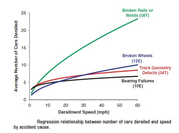
_____
Analysis of Causes of Major Train Derailment and Their Effect on Accident Rates: a 2012 study:
Analysis of the causes of train accidents is critical for rational allocation of resources to reduce accident occurrence in the most cost-effective manner possible. Train derailment data from the FRA rail equipment accident database for the interval 2001 to 2010 were analyzed for each track type, with accounting for frequency of occurrence by cause and number of cars derailed. Statistical analyses were conducted to examine the effects of accident cause, type of track, and derailment speed. The analysis showed that broken rails or welds were the leading derailment cause on main, yard, and siding tracks. By contrast to accident causes on main tracks, bearing failures and broken wheels were not among the top accident causes on yard or siding tracks. Instead, human factor-related causes such as improper use of switches and violation of switching rules were more prevalent. In all speed ranges, broken rails or welds were the leading cause of derailments; however, the relative frequency of the next most common accident types differed substantially for lower-versus higher-speed derailments. In general, at derailment speeds below 10 mph, certain track and human factor causes-such as improper train handling, braking operations, and improper use of switches- dominated. At derailment speeds above 25 mph, those causes were nearly absent and were replaced by equipment causes, such as bearing failure, broken wheel, and axle and journal defects. These results represent the first step in a systematic process of quantitative risk analysis of railroad freight train safety, with an ultimate objective of optimizing safety improvement and more cost-effective risk management.
_____
Optimization of Ultrasonic Rail-Defect Inspection for Improving Railway Transportation Safety and Efficiency: a 2014 study:
Broken rails are the most frequent cause of freight-train derailments in the United States. Consequently, reducing their occurrence is a high priority for the rail industry and the U. S. Federal Railroad Administration. Current practice is to periodically inspect rails to detect defects using nondestructive technology such as ultrasonic inspection. Determining the optimal rail inspection frequency is critical to efficient use of infrastructure management resources and maximizing the beneficial impact on safety. Minimization of derailment risk, costs of inspection vehicle operation, rail defect repair, and corresponding train delay are all affected by rail inspection frequency. However, no prior research has incorporated all of these factors into a single integrated framework. The objective of this paper is to develop an analytical model to address the trade-offs among various factors related to rail defect inspection frequency, so as to maximize railroad safety and efficiency. The analysis shows that the optimal inspection frequency will vary with traffic density, rail age, inspection technology reliability, and other factors. The optimization model provides a tool that can be used to aid development of better-informed, more effective infrastructure management and accident prevention policies and practices.
______
Derailment risk and dynamics of railway vehicles in curved tracks: Analysis of the effect of failed fasteners: a 2015 study:
The effect of the fastener’s failure in a railway track on the dynamic forces produced in the wheel-rail contact is studied using the simulation software VAMPIRE to assess the derailment risk of two different vehicles in two curves with distinct characteristics. First, a 3D-FEM model of a real track is constructed, paying special attention to fasteners, and calibrated with displacement data obtained experimentally during a train passage. This numerical model is subsequently used to determine the track vertical and lateral stiffness. This study evidences that although the track can practically lose its lateral stiffness as a consequence of the failure of 7 consecutive fasteners, the vehicle stability would not be necessarily compromised in the flawed zone. Moreover, the results reveal that the uncompensated acceleration and the distance along which the fasteners are failed play an important role in the dynamic behavior of the vehicle-track system, influencing strongly the risk of derailment.
______
Wear Enhancement of Wheel-Rail Interaction by Ultrasonic Nanocrystalline Surface Modification Technique: a 2017 study:
In this study, an ultrasonic nanocrystalline surface modification (UNSM) technique was applied to normal and heat-treated rails made of 60 kgK steel to enhance the wear resistance of the wheel-rail interaction. The hardness and compressive residual stress values of the untreated and UNSM-treated rails were measured by the Brinell hardness tester and X-ray diffraction technique, respectively. The surface layer of the normal and heat-treated rails was hardened by the UNSM treatment process. The compressive residual stress was also induced in the surface layer by severe plastic deformation generated by the UNSM treatment process. The heat treatment of the rail was good enough to improve the wear resistance, but the effect of the UNSM treatment process was revealed to be greater than that of heat treatment on the wear resistance. According to the obtained results, that the wear and fatigue of the wheel-rail interaction may be improved with the application of the UNSM treatment process since the harder material provides a benefit in reducing whole-system maintenance and repairing costs. Dynamic tests, which can simulate a similar condition to the real wheel-rail interface, need to be performed in order to apply this treatment to a real field.
_____
Using a wheel pair with a counter-flange to prevent derailment: a 2017 study:
The authors propose an engineering solution for a wheel pair with a counter-flange that satisfies the existing standards of vertical and horizontal dynamics and the movement stability index. An improved profile of a rail wheel with a counter-flange is developed. It provides additional contact in the horizontal plane in the situation of transverse vibrations of the wheel pair against the rail track, adds to carriage stability and increases the wheel’s resistance to derailment when passing a curved part of the tracks or when rails deflect due to force interaction. The wheel pair profile is stabilized with an additional running track and counter-flange that prevents derailment when base flange of the wheel rolls onto the working surface of the rail or when there is a way spacer due to rail spring deformation. The proposed design of the wheel pair is covered by an Ukrainian utility model patent.
_____
_____
Train travel is much safer than other forms of travel:
_
Train travel is still a very safe mode of transportation. Though train derailments are actually quite common, motorcycle and car travel are the most risky forms of transportation.
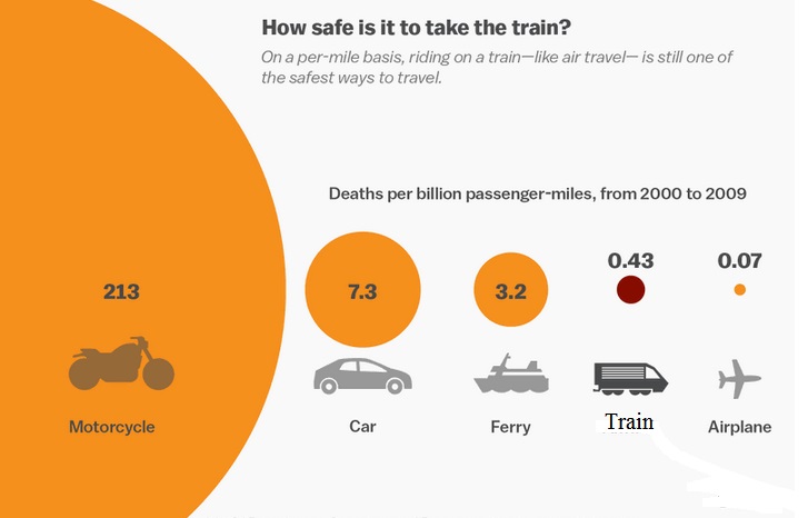
Train accidents are terrifying, and get lots of public attention when they occur. But the truth is that — just like plane travel — on a per-mile basis, riding on a train is much safer than in a car.
_
The most recent comparison study, conducted in 2013 by economist Ian Savage, compared fatality rates for several different forms of travel in the US. The number of rail deaths from year to year ranges widely (because many can happen in large, sporadic accidents), but between 2000 and 2009, a person was about 17 times more likely to die while traveling in a car, compared to a train, for the same distance. According this study by economist Ian Savage, trains are the second-safest mode of transportation in the U.S. Between 2000 and 2009, the number of deaths per billion passenger-miles caused by trains was 0.43. In comparison, the number of deaths caused by cars was 7.3 and the number of deaths caused by motorcycles was a disturbing 213. But trains are still only the second-safest option, with the first-safest option being flying. According to that same study, the number of deaths per billion passenger-miles caused by airplanes is a measly 0.07. And this statistic is just one of many that illustrate just how safe air travel is. Last September, the Swiss-based Bureau of Aircraft Accidents listed the average rate of crashes was 2.1 per one million flights, which means you have a one in 15,000,000 chance of being in a plane crash. You are 15 times more likely to get struck by lightning. And this statistic was determined after the series of high-profile crashes that made aviophobes swear off flying for good, like the mysterious MH370 disappearance and the downing of MH17. Similarly, in 2012, The New York Times cited Arnold Barnett, a professor of statistics at M.I.T., for this statistic: between 2008 and 2012, the odds of dying in a plane crash for passengers in the U.S. were one in 45 million flights. The Times further emphasized the point by revealing that with those odds, a passenger could fly every single day for an average of 123,000 years before dying in a plane accident. But the overwhelming evidence that flying is safe should not take away from your confidence in train travel. Ultimately, it is also very rare to die in a train crash, especially for passengers. According to the National Transportation Safety Board’s stats, of the 891 train deaths in the U.S. in 2013, only six of them were passengers. The vast majority were pedestrians or drivers who were struck by a train. While trains have more accidents, plane crashes typically kill a lot more people per incident. In 2014, there were 990 plane-related deaths, but only 21 fatal airliner accidents. That’s an average of 47 deaths per flight. So if you think of accidents in terms of how deadly they are of average, then flying would be significantly more deadly than riding a train. But at the end of the day, the main point through all these statistics is: both flying and riding in trains are safe ways to travel. When you’re in a car, however, always wear your seat belt. And just try to avoid motorcycles altogether.
_
Derailments are fairly common — but most are relatively harmless:
Across the US, trains derail more often than you might think — in 2014, for instance, there were a total of 1,241 derailments. But the majority of them cause no injuries or deaths, and often only cause damage to the cargo they’re carrying. This is partly because just a slim minority of US trains carry passengers (most carry freight), and because most trains cars are designed to survive some level of impact. Additionally, most miles of track are in relatively rural, unpopulated places. Most derailments are relatively benign, and can be compared to a person walking down the street, tripping, getting back up, and continuing on her or his way. Unless derailed cars crash into houses, strike passenger trains, or release hazardous material into a neighborhood, derailments do not normally affect civilians. Also derailments have become dramatically less common over the years, with a huge dip in the annual rate in the 1980s. The decline was mainly caused by improvements in technology that were implemented after the freight industry was heavily deregulated in 1980, allowing companies to turn a profit, so they could invest more in track and new equipment. Years ago, for instance, engineers were required to manually spot track signals and stop their trains to prevent collisions. Nowadays, automated systems do that, as well as monitor train speeds to ensure they don’t exceed preset limits.
_
Derailments are most often caused by track problems:
Derailments can sometimes be caused by operator error or equipment malfunction — but more often, they’re due to track problems. Bibel notes in his book, “Broken, settled, spread, shifted, or overturned rails account for about 50% of the equipment related derailments.”
Remember: ‘The best protection against derailments is good track’.
______
______
My efforts to improvise railway system:
Thousands of engineers and researchers are working worldwide to improvise railway system. I have already discussed many latest technological innovations to prevent and early detect derailments. Everybody knows that wheels stays and runs on rails [on straight tracks, curved tracks and at switches], mainly because of weight of train, coning of wheel tread, flanges of wheels, and geometry & profiles of rails and tracks. We already have alternative substitute guidance mechanisms, such as low-reaching parts of bogie frame, axle box, or brake disc, that can minimize lateral deviation of wheelsets to limit consequences after derailment. We also have high-speed train guidance system to detect deviation of wheel from its central optimal position, followed by an automatic mechanical system to move it back to the best contact point. We have EDT101 derailment detector which detects derailment and apply emergency brake. We have vibration sensor that detects excessive vibrations just at the time of derailment and automatically apply brake. I was thinking whether any intermittent temporary simple mechanism can be invented so that wheels and rails adhere strongly just before derailment, at derailment and immediately after derailment, to prevent derailment or reduce consequences after derailment.
_
Materials that can be magnetized, which are also the ones that are strongly attracted to a magnet, are called ferromagnetic. These include iron, nickel, cobalt, some alloys of rare-earth metals, and some naturally occurring minerals such as lodestone. Primarily, iron is an element while steel is an alloy comprising of iron and carbon. However, in this alloy iron is present in a greater quantity. You can add various other metals to steel so as to produce alloys that have different properties. For example, if chromium is added to steel, stainless steel is the product. A basic stainless steel has a ‘ferritic’ structure and is magnetic. The magnetic properties of stainless steel are very dependent on the elements added into the alloy, and specifically the addition of nickel can change the structure from magnetic to non-magnetic.
_
Railroad wheels are solid steel and they are rigidly attached to a steel axle. Rails themselves are made up of steel. Rail wheels are made up of steel having carbon content less than 0.5%. Rails are also made up of steel having carbon, up to a maximum of 0.82%, and manganese, to a maximum of 1.7%, to produce hard, wear resisting rails. So rails, wheels and axles are all made up of steel which can be magnetized. Iron gets magnetized faster but loses its magnetism as soon as the inducing magnet is removed. Hence soft iron is said to have high susceptibility but low retentivity. This property of soft iron is very useful in making temporary electromagnets where we need strong but temporary magnets. If the magnets used in these devices were to retain their magnetism for a longer period, the devices would not function properly. Steel is slow to be magnetized but retains the acquired magnetism for a long time. Steel is said to have low susceptibility but high retentivity. Steel is used for making magnets. Soft iron is iron that has low carbon content and is easily magnetized and demagnetized, used to make the cores of solenoids and other electrical equipment.
_
Permanent magnets are magnets retain their magnetism once magnetized. These are the most common type of magnets that we know and interact with in our daily lives. E.g. magnets on our refrigerators. These magnets are permanent in the sense that once they have been magnetized they retain a certain degree of magnetism. Permanent magnets are generally made of ferromagnetic material. Such material consists of atoms and molecules that each have a magnetic field and are positioned to reinforce each other. Temporary magnets are materials magnets that perform like permanent magnets when in the presence of a magnetic field, but lose magnetism when not in a magnetic field. Paperclips, iron nails and other similar items are examples of temporary magnets. Temporary magnets are used in telephones and electric motors amongst other things. Electromagnets are wound coils of wire that function as magnets when an electrical current is passed through. By adjusting the strength and direction of the current, the strength of the magnet is also altered. Had it not been for electromagnets we would have been deprived of many luxuries and necessities in life including computers, television and telephones. Electromagnets are extremely strong magnets. They are produced by placing a metal core (usually an iron alloy) inside a coil of wire carrying an electric current. The electricity in the current produces a magnetic field. The strength of the magnet is directly proportional to the strength of the current and the number of coils of wire. Its polarity depends on the direction of flow of current. While the current flows, the core behaves like a magnet. However, as soon as the current stops, the core is demagnetized. Electromagnets are most useful when a magnet must be switched on and off as in large cranes used to lift cables and rods in construction.
_
Temporary magnet:
The figure below shows that chains of paper clips can be hung from a magnet.
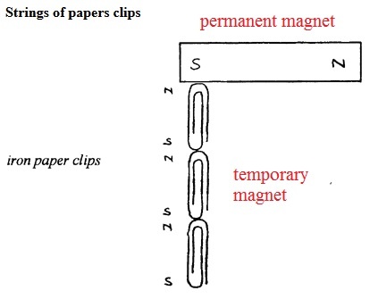
Each paper clip magnetises the one below it by induction and the unlike poles so formed attract. If top paper clip is removed the chain collapses. So paper clips are temporary magnet attached to permanent magnet.
_
Electromagnet:
The magnetic field is created by a coil of wire around the iron core that carries a current.
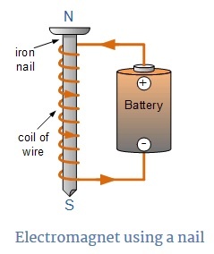
An electric current flowing in a wire creates a magnetic field around the wire. To concentrate the magnetic field in an electromagnet, the wire is wound into a coil with many turns of wire lying side by side. The magnetic field of all the turns of wire passes through the center of the coil, creating a strong magnetic field there. A coil forming the shape of a straight tube (a helix) is called a solenoid. The direction of the magnetic field through a coil of wire can be found from a form of the right-hand rule. If the fingers of the right hand are curled around the coil in the direction of current flow through the windings, your right thumb points to the North Pole. Much stronger magnetic fields can be produced if a “magnetic core” of a soft ferromagnetic (or ferrimagnetic) material, such as iron, is placed inside the coil. A core can increase the magnetic field to thousands of times the strength of the field of the coil alone, due to the high magnetic permeability of the material. This is called a ferromagnetic-core or iron-core electromagnet.
The strength or intensity of a coils magnetic field depends on the following factors.
- The number of turns of wire within the coil.
- The amount of current flowing in the coil.
- The type of core material.
_
Friction between two surfaces can be improved by creating a rougher or more adhesive point of contact, by pressing the two surfaces harder, removing lubrication between surfaces and remove wheels or bearing to create sliding friction. Here I am postulating increased adhesion (friction) between wheel tread & flanges and rail surface transiently to prevent derailment or reduce lateral migration of wheelset after derailment. I propose the idea of making wheels and areas of rails in contact with wheels, temporary magnets attracted to each other, increasing adhesion of wheels over rails to prevent derailment or to reduce consequences of derailment in case of derailment. This transient temporary mechanism is to be activated only when derailment detector/sensor on running train detects derailment or driver anticipate derailment.
_
Making of electromagnet by using axle as core:
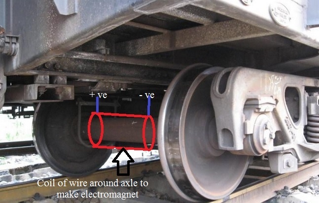
As seen in the figure above, I propose an electromagnet constructed by making a coil of wire wound around axle which functions as steel core of electromagnet. Coil of wire is mounted on spool which is pulled over axle and hangs from chassis of coaches or wagons. The axle will freely rotate as train runs without touching the spool and the coil. In normal train operation, no current flows in wire. When derailment detector/sensor detects impending derailment or train driver suspect impending derailment, a current is passed through coil of wire encircling axle so that axle becomes core of electromagnet. I would call it ‘axle core electromagnet’ (ACE). This ACE will immediately make axle and wheels powerful magnets as wheels are fixed to axle. Every coach/wagon including locomotive would have ACE in each axle-wheel-set and all will get activated simultaneously.
_
Can rotating axle indeed become magnetic?
Yes.
Read Patent: WO 2013063661 A2/A3
Electromagnet with rotating iron core:
When DC current is brought to coils of an electromagnet, which are mounted on a spool, pulled over a movable iron core, around the spool an electromagnetic field is created, which turns the iron core to an electromagnet with protruding poles. If this iron core rotates around its axis, the protruding magnetic poles create a rotating magnetic field, which doesn’t lose its magnetic characteristics although the electromagnet coils which create it are immovable. Yes, if next to the poles (N,S) of the rotatable axle steel core, another stationary iron core with a copper wire coil is positioned; then a current is induced in the that coil because of change of magnetic flux flowing through the iron core.
_
Will rotating magnetic axle display dynamo effect?
No.
Electricity can be generated by moving a wire near a magnet, or by moving a magnet near a wire. This is called the dynamo effect. The large generators used in power stations use electromagnets instead of permanent magnets. Electricity is generated when the electromagnet rotates inside coils of wire. The more turns there are on the coils of the electromagnet, the greater the size of the voltage generated. Here steel axle is magnetized and rotating but will not generate current suo-motu as it is rotating on its axis in such way that north pole and south poles remain at same place although rotating. In electromagnets of generator, the spinning electromagnet induces a voltage in the stator coil each time it passes by, but it spins on axis perpendicular to axis of north south poles as seen in the figure below:
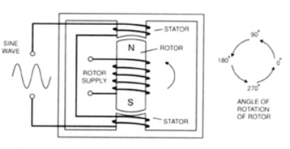
__
When derailment detector or sensor detects impending derailment of any train, immediately ACE is activated by passing strong current in the coil encircling the axle steel core. Instantaneously strong magnetic force is activated in running axles and thereby running wheels. Simultaneously emergency air brake is also activated. Magnetic wheels would attract rails on which they are running increasing adhesion. This increased adhesion along with emergency brake will prevent derailment; and if flange climb has already occurs, it will prevent further lateral migration of wheel set and keep train on track despite derailment. Flange climb derailment in low speed takes time. This kind of derailment has possibility to take some kind of measures before derailment accident. Ballast is made up of limestone and granite stone that are not magnetic except those with high iron content. So magnetic wheel rail attraction would not affect ballast stones.
_
If you try to pull a magnet off a contact surface at a right angle, you need much more strength than if you slide the magnet sideways. The maximum adhesive force that is specified for each magnet applies, among other factors, when the holding strength is at a right angle to the contact surface. If the holding strength is not at a right angle to the contact surface, its maximum value also depends on the frictional force between the object and the magnet. If the maximum value is exceeded, the magnet starts slipping.
The ‘magnetic wheel holding strength’ on rail is at right angle.
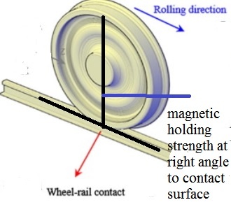
Since all wheels of all coaches including locomotive are exerting magnetic force on rail at right angle, it will be able to prevent overturn derailment and flange climb derailment or at least reduce lateral wheelset movement after flange climb derailment.
_
Was electromagnet used in any emergency situation earlier?
Yes.
Magnetic track brake:
The power of electromagnetic track brakes comes from electromagnetic attraction between the brake and the track. They are intended to provide retardation beyond the adhesion limit of the wheels alone, which ultimately is limited by the weight of the vehicle. Track brakes are fitted on the bogies between each pair of wheels and in line with the running rails. In operation they are first dropped into position on the rails, using air actuators, and then current is applied to strong electromagnet coils within the shoes. This pulls the brake shoes hard against the track with a force that can exceed the vehicle’s weight, and strong braking forces result. Because of the risk of damage to the trackwork at railroad switches, etc., track brakes are typically recommended for use only in emergency situations, adding their force to the main brakes (electric brakes and disc brakes) – especially vital if train loses control or the disc brakes have failed
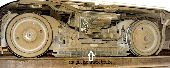
By applying braking force directly to the rail, magnetic track brakes offer levels of performance and reliability that have been proven through extensive in-service operation around the world.
_
Eddy current brake:
A conductive surface moving past a stationary magnet will have circular electric currents called eddy currents induced in it by the magnetic field. The circulating currents will create their own magnetic field which opposes the field of the magnet. Thus the moving conductor will experience a drag force from the magnet that opposes its motion, proportional to its velocity. The electrical energy of the eddy currents is dissipated as heat due to the electrical resistance of the conductor. In an eddy current brake, the magnetic field is be created by an electromagnet so the braking force can be turned on and off or varied by varying the electric current in the electromagnet’s windings. Another advantage is that since the brake does not work by friction, there are no brake shoe surfaces to wear out, necessitating replacement, as with friction brakes. A disadvantage is that since the braking force is proportional to velocity, the brake has no holding force when the moving object is stationary, as is provided by static friction in a friction brake, so in vehicles it must be supplemented by a friction brake. Eddy current brakes are used to slow high-speed trains. Japanese Shinkansen trains had employed circular eddy current brake system on trailer cars since 100 Series Shinkansen. However, N700 Series Shinkansen abandoned eddy current brakes in favour of regenerative brakes.
_
What I am proposing is to make train wheels magnetic transiently so that they hold on to rails due to strong magnetic attraction to prevent derailment or reduce consequences by keeping train on track after derailment. These ACEs in all coaches/ wagons working simultaneously and immediately with full force would make them work as emergency brake also. For slippery rails, mild application of wheel magnetic force transiently can assists adhesion during braking and acceleration.
______
______
The moral of the story:
_
- United States has the world’s longest railway network with an operating route length over 250,000km. Indian railway carries about 8.4 billion passengers per year which is highest in the world. China not only has the safest passenger trains, but also by far the busiest tracks.
_
- Rail transport is highly efficient as compared to road transport because coefficient of rolling resistance between steel rail and steel wheel is very small of the order of 0.0001 as compared to 0.01 of road transport of car and trucks. Efficiency is slightly lost due to prevailing sliding friction between flange and inner face of rail which does not exists in road transport and higher tare weight (i.e. weight of empty vehicle) per unit carrying capacity which is not so in road transport. Rail is far more efficient for transportation of freight than roads and air.
_
- Although the railways keep our 21st-century economy running, it’s essentially a 19th-century technology. Rail operators have known for decades that technological fixes could prevent rail disasters but they have been dragging their feet because those fixes are expensive and complicated.
_
- Classification of railway accidents, both in terms of cause and effect, is a valuable aid in studying rail accidents to help prevent similar ones occurring in the future. Systematic investigation for over 150 years has led to the railways’ excellent safety record (compared, for example, with road transport).
_
- A derailment is when a railroad car or locomotive is no longer properly supported by the rails under it. A derailment occurs when a when one or more rolling stock wheels of a train runs off its rails. This does not necessarily mean that it leaves its track. Derailments are the most common type of train accident, and preventing them has long been a focus of the rail industry and the government. Train derailments are one of the major undesirable events to be considered in railway safety system and potentially pose serious hazards to human health and safety. A derailment does not necessarily mean someone failed to do their job, was negligent, or not paying attention – like a flat car tire, sometimes they just happen.
_
- A 2014 study in the US found that derailments are most common class of railway accidents i.e.70% of all accidents. According to Indian official figures, of a total of 586 rail accidents in the last five years, nearly 53 per cent were due to derailments. Broken rails and welds, track geometry defects, bearing failure, wheel profile defects, wrongly loaded wagons, train mishandling and human error account for most of derailments.
_
- Railway rails are subject to very high stresses and are made of very high quality steel. The heavier the rails and the rest of the track work; the heavier and faster the trains these tracks can carry. All rail tracks are not same. Standards are established for maximum distance between rails (gauge), maximum dips in each rail (profile), and maximum deviation from straightness (alignment). The quality of rail track is based on track structure, track geometry, and inspection frequency and method. The class of a section of track determines the maximum possible running speed limits and the ability to run passenger trains. The higher the track class (quality), the more stringent are the track safety standards and thus a higher maximum train speed is allowed. We need separation of freight and passenger traffic along different lines and adjustment of track geometry design to most frequent traffic type. Poor nations use the same track for all kinds of rail traffic and therefore more susceptible to derailment.
_
- The ballast provides maximum stability and minimum track deformation as trains run over tracks and they have high permeability to allow adequate drainage of water from the tracks in the rainy season. For high speed, high frequency lines, slab track would be preferable over sleepers (ties) and ballast any day. It is basically track fixed directly to reinforced concrete slabs and has the advantage of increased stability, reduced susceptibility to water damage and lower maintenance costs. It is however expensive, so sleepers and ballast are used instead.
_
- Conicity of wheel tread (wheel tread is present in the shape of cone with a slope of 1 in 20 or 1 in 40) provides guidance on straight tracks and differential action on curved tracks. However it also gives rise to hunting oscillation and wear of inner edge of rail with resultant gauge widening.
_
- Trains stay on the rail tracks because of its weight, the coning wheels, the rail head slightly curved to match coning wheel tread and the rails are set at an inward angle; and not because of flanges on the inside of the wheels. Coning is such that outside diameter is smaller than inside diameter of wheel to help negotiate a curve. The coning helps, not only in covering turns, but also to maintain the train in center of tracks during normal running of train on straight track. A flange of the wheel is a 28-millimetre-high ridge on the inside edge of the wheel as an extension of the coning of wheel tread. Whether straight track or curved track, flanges are only a last resort to prevent the wheels becoming derailed i.e. they’re a safety feature. However, flange can negotiate the points (switches or turnouts) to change tracks because switches are designed for wheels with inside flanges. So changing track is a function of flanges.
_
- The wear and fatigue life of wheel-rail interactions depend greatly on properties such as contact stress, surface hardness, and compressive residual stress. Most of the damage on the rail is caused by rolling contact wear (RCW) and rolling contact fatigue (RCF) since train wheels and rails are always in contact with dynamic motion, in addition to environmental influences. Wear of wheel and rail involves both plastic deformations, and abrasion of surfaces; cause of this phenomenon may be high dynamic forces at the wheel–rail contact that is exacerbated by bad maintenance of rolling stock & track, and absence of effective and appropriate use of lubrication. Once the rail surface is damaged, the wheel-rail profile is mismatched and wear is accelerated by friction. This wheel-rail interaction affects fuel consumption, derailment risk, and vehicle stability.
_
- Expansion of a mile long section of rail could be more than 1 meter in very hot weather leading to rail buckling. Very cold weather can cause rail fracture due to contraction of rail. Both buckling and fracture can cause derailment. Weather has role in derailment by temperature fluctuations, strong winds, rain & flooding, and snow.
_
- A major problem of jointed track is cracking around the fishplate bolt holes, which can lead to breaking of the rail head and derailment. Jointed track is still used in many countries on lower speed lines and sidings, and is used extensively in poorer countries due to the lower construction cost and the simpler equipment required for its installation and maintenance. For modern usage, particularly where higher speeds are required, the lengths of rail are welded together to form continuous welded rail (CWR). Apart from the more comfortable ride for passengers, the advantages included economic ones, such as an extension of rail life by between 30 per cent and 40 per cent, savings in the cost of track maintenance, extended sleeper life, and reduction in fuel costs and wear and tear on rolling stock, as well as the important gain in safety (less derailment) resulting from the elimination of rail joints. CWR does not buckle as it is installed in warm enough temperatures to keep kinking from occurring. However, when the rails are already heated by weather, the added energy from the train traveling at high speed over the tracks can be enough to cause them to become too hot and buckle. The load the train puts on the track (vertically) is dependent on the speed of the train, the diameter of the train’s wheels, and the weight that the train is carrying. To change the amount of vertical load on the track, the diameter of the wheels can’t change, nor can the weight of the train, so the only thing to change is the speed. So trains have to slow down when it is too hot.
_
- At speed above 225 km/h (140 mph) on straight track, hunting oscillation of wheels occur damaging track and wheels, and potentially causing derailment. High speed rail (HSR) have improves design of wheel suspensions to reduce hunting oscillations, and better track stability due to slab track. So most high-speed trains today still use steel wheels, rather than more expensive Maglev technologies.
_
- The maximum speed a train can proceed around a turn is limited by the radius of turn, the centre of gravity height, the wheel gauge and whether the track is superelevated / canted.
_
- Train derailment at curves can occur at normal speed, fast speed or very slow speed depending on mechanism of derailment. The guidance system of railway vehicles relies on the steering effect of the conicity of the wheel treads on moderate curves without any flange contact. “Train overturn derailments” are different phenomena from “flange climb derailments” on curves. Train overturn derailment occurs on curves if train is too fast or too slow. Fast speed giving rise to high centrifugal force, plus accompanied by high centre of gravity of train will cause overturn derailment. The critical speed is heavily influenced by the ratio of C.G. height of the vehicle to track gauge width. Train overturn derailment can also occur at very slow speed either due to high centre of gravity of vehicle or high superelevation or both together. The lateral contact forces between wheel and rail rarely influence to the overturn movement of the vehicle. On sharper curves flange contact takes place, and the guiding effect of the flange relies on a vertical force (the vehicle weight). A flange climbing derailment on outer rail can result if L/V ratio is excessive, where L and V refer to the lateral and vertical forces acting upon the rail and wheel. The higher the L/V ratio, the more likely the car is to derail. If the L/V ratio gets too high, the wheel flange will be pressing against the rail face, and during a turn this will cause the wheel to climb the face of the rail, potentially derailing the railcar. L/V ratio greater than 0.6 is considered to be hazardous. L/V ratio depends heavily upon the friction coefficient, and friction coefficient changes every moment according to the conditions present. Flange climb is more likely to occur in curves when flanges are worn or have improper angles or if the rail head is side-worn (side-cut) as it will change L/V ratio. So flange climb derailment can occur at slow or moderate speed on curves. A slow, heavy freight train is far more likely to derail on a curve by rail rollover, wide gauge, or flange climb.
_
- Railroad switch/point/turnout-related derailments collectively cause almost the half of all train derailments.
_
- Despite popular acceptance of the theory of bunching derailment due to sudden application of the brakes, the “bunching” derailments really result from oscillation brought about by track irregularities and defective springs; apart from positive defects in tracks or trucks, and not due to sudden application of the brakes per se. In other words, if track and truck are in excellent conditions, sudden application of the brake throughout the train will not cause derailment. So emergency brake causing derailment is indeed rare.
_
- US federal study predicts ten oil train derailments per year. Track problems are blamed on 59% of the oil train derailments. Weight, oil sloshing and cold temperatures are among the issues that might be exacerbating the problem, according to rail safety experts. Petroleum crude oil unit trains transporting heavily loaded tank cars will tend to impart higher than usual forces to the track infrastructure during their operation. These higher forces expose any weaknesses that may be present in the track structure, making the track more susceptible to failure. The oil can slosh as cars move, causing higher dynamic loads and increases the stress on the track. As temperatures drop, steel rails progressively shrink, amplifying the potential for any existing defect to cause a failure. Frozen ballast also causes rail to undergo greater shocks under the load of heavy trains.
_
- Oil train derailment may lead to rupturing or explosion of tank cars, spilling their contents, polluting waterways and igniting spectacular fires that burned for days. Various oil train derailments have deepened safety concerns and if an oil-train derailment were to occur in a densely populated area, massive casualty would ensue.
_
- Trains are used to carry a wide range of hazardous materials, from phosphorus to chlorine and other chemicals. Freight trains have spilled hazardous materials in recent years including: vinyl chloride, acids, caustics and cyanide. In some spill-causing derailments, hazardous materials are released as gases, allowing them to travel wherever the wind blows. In other instances, liquids penetrate the water supply and the land, where they ultimately go into streams and rivers. Spills can result in fires and other property damage as well as the loss of business in towns that must be evacuated because of spills. In short, the damage caused by the spilling of hazardous materials due to train derailments can affect almost anything in the area. People, animals, plants, and commerce can all suffer as a result of a toxic spill.
_
- Prevention of derailment at curves include: superelevation of outer rail, designing of lower C.G. height vehicles, appropriate L/V ratio, prevention of wear and fatigue of wheel-rail interface and flanges, installation of check rails at sharp curves, prohibition of over-speed curving by signalling systems, Positive Train Control system and train drivers’ education and training.
_
- Broken rail preventive measures include rail inspection, rail grinding, rail repair, and renewal. Improved rail quality, composition, and joining techniques could lead to better wear characteristics and a longer lifespan of the rail. No ideal material that does not wear and or suffer from fatigue for rail and wheel applications has been found yet. However, the bainitic steels exhibited a better wear resistance compared to the existing pearlitic and ferritic-pearlitic steels due to the presence of typical bainitic morphology. The surface of the rail head is open to foreign objects, vibration, slip, friction and stress. The heat treatment of the rail is good enough to improve the wear resistance by increasing rail surface hardness.
_
- Although derailment severity is directly proportional to derailment speed, broken rail and weld are more likely to cause severe derailment than bearing failure, track geometry defects and wheel defects at same derailment speed. Also, broken rails and welds are the leading derailment causes on main tracks, while human error tends to be more prevalent in train yards or on siding tracks. Therefore rational allocation of resources to reduce derailment occurrence in the most cost-effective manner demands, maximum resources to be allocated for prevention and early detection of broken rails and welds.
_
- The heavy loads, high speed and high frequency of today’s trains can cause rails to fail in service unless regular inspections are performed. Rail inspection is the practice of examining rail tracks for flaws that could lead to catastrophic failures. Visual inspections, magnetic induction and ultrasonic are common methods of rail inspection. However, some of the worst derailments have occurred on tracks recently inspected by the current generation of technology. With increased rail traffic carrying heavier loads at higher speeds, a quicker more efficient way of inspecting railways is needed.
_
- Minimization of derailment risk, costs of inspection vehicle operation, rail defect repair, and corresponding train delay are all affected by rail inspection frequency. Rail inspection frequency should vary with traffic density, rail age, inspection technology reliability etc. so as to maximize railroad safety and efficiency.
_
- In order to prevent and/or detect derailment, various detectors and sensors can be installed on train and/or rail track to monitor various parameters like derailed wheelset, derailed axle, flange climb, gauge spreading, wheel defect, rail cracks and fractures, bridge expansion and contraction, curve detection, wheel vibration detection, hot axle and hot bearings detection etc.
_
- Various train protection systems like AWS, TPWS, ATP, ACD, ETCS, and PTC are available to ensure safe railway operation in the event of human failure to prevent derailments and other railway accidents.
_
- Positive Train Control (PTC) works by combining radio, cellular, and GPS technology with railway signals to allow trains to identify their locations relative to other trains on the tracks. The primary goal of PTC is to prevent train collisions, but they can also work to prevent derailments caused by excessive speed.
_
- Artificial intelligence (AI) equipped locomotives can automate detection of rail track flaws that could cause derailments.
_
- High-speed rail (HSR) has operational speeds in excess of 200 km/h (120 mph). HSR technology could be wheel based or Maglev and often operates on dedicated track that is surveyed and prepared to accommodate high speeds. Wheeled high speed passenger train can derail similar to ordinary passenger train. Alternative substitute guidance mechanisms, such as low-reaching parts of bogie frame, axle box, or brake disc, can minimize lateral deviation of wheelsets to limit consequences to least after derailment.
_
- Shinkansen bullet train is a network of high-speed railway lines in Japan with maximum operating speed of 320 km/h (200 mph). Over the Shinkansen’s 50-plus year history, carrying over 10 billion passengers, there have been no passenger fatalities due to derailments or collisions, despite frequent earthquakes and typhoons. India is going to install Japanese bullet trains but can India maintain safety record of Japan?
_
- López Gómez high-speed train guidance system prevents squeaking noises, limits wear-and-tear and significantly improves the comfort of the ride. This system uses precise computer technology to detect the rotational speed at which a train wheel is travelling and then calculate where it is contacting the rail. When the wheel deviates from its central optimal position, an automatic mechanical system moves it back to the best contact point. This will prevent derailment of high speed trains.
_
- In order to achieve much faster operation over 500 km/h (310 mph), innovative Maglev technology has been researched which uses magnets to levitate the train above the track (guideway), reducing friction and allowing higher speeds. Maglev trains float on a cushion of air, eliminating friction. Maglev train cannot derail because there are no wheels and no rails.
_
- The Indian Railways network gives more importance to punctuality at the cost of safety. The traffic authorities, in a bid to maintain punctuality in train running, are reluctant to give permission to undertake minor repair and maintenance work, so such maintenance work is undertaken without permission from traffic authorities. Railway engines and coaches continue to run as per their normal speed on ‘under maintenance tracks’ resulting in derailment.
_
- India’s train derailment figures show bizarreness. Human failures are blamed more often than track failure for derailment on mainline which is quite opposite of the rest of the world. 47% of consequential rail accidents took place due to failure of railway staff. Lapses by the railway staff include carelessness, poor maintenance, adoption of short-cuts, and non-observance of safety rules.
_
- Human error, over-worked tracks, inadequate maintenance, carrying out repairs without block, shortage in safety staff, and under-investment are root causes of derailments in India. 40 per cent of the lines on the Indian railways are being used beyond their official capacity. Total length track renewal is 115,000 km which will take at least 40 years to complete.
_
- Train travel is still a very safe mode of transportation. Derailments are fairly common but most are relatively harmless. Some derailments are terrifying, and get lots of public attention, but train travel is much safer than motorcycle and car travel. Unless derailed wagons/coaches crash into houses, strike passenger trains, or release hazardous material into a neighbourhood, derailments do not normally affect civilians except passengers of the derailed train. Only flying is safer than train travel and it is very rare to die in a train crash. Many deaths attributed to railway accidents are pedestrians struck while crossing rail track; and suicides occurring on the railways outnumber passenger fatalities of train crash.
_
- The safest place to sit on a train is choosing a coach located one or two back from the middle of the train and choosing a rear-facing aisle seat.
_
- The best protection against derailments is good track.
_
- I propose an electromagnet constructed by making a coil of wire wound around axle which functions as steel core of electromagnet. I would call it ‘axle core electromagnet’ (ACE). These ACEs will immediately make axles and wheels of train powerful magnets when electric current passes through coil of wire encircling axles. These magnetic wheels of train will hold on to rails due to strong magnetic attraction to prevent derailment or to reduce consequences by keeping train on track after derailment. These ACEs will be activated only when derailment detectors or sensors on train detect impending derailment or driver detects impending derailment. Flange climb derailment in low speed takes time. This kind of derailment has possibility to take some kind of measures before derailment accident. These ACEs can also work as an emergency brake when used with maximum current, and overcome slippery rails by increasing adhesion during braking and acceleration when used with minimum current.
_____
Dr Rajiv Desai MD
October 28, 2017
_____
Postscript:
Is human failure limited to only Indian railways? No. In my view, human failure pervades all aspects of Indian life right from legislature, executive, judiciary, media, education and health. I hope Indian railway officials read this article and take measures to control derailment epidemic.
_____
101 comments on “DERAILMENT”
Leave a Reply

Our AI-powered service drives targeted website traffic at a fraction of the cost of paid ads. Contact us to grow your audience today.
https://blankslatelife.com/